MTU-s with Redundant Spoke Circuits
In this scenario, MTU-s has redundant spoke circuits PW1 and PW2 connected to PE1 and PE2, respectively. User should configure MTU-s so that one PW is Primary and the other as Secondary. With P1 designated as Primary and PW2 designated as Secondary, MTU-s announces that PW1 is in the Active mode and PW2 is in the Standby mode. If PW1 fails, MTU-s performs a switchover by announcing PW2 as Active and PW1 as Standby.
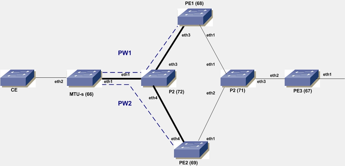
Figure 10-2: MTUs with Redundant Spoke Circuits
MTU-s
#configure terminal | Enter configure mode. |
(config-if)#lo | Identify the loopback interface to configure (lo). |
(config-if)#ip address 66.66.66.66/32 | Set the IP address of the loopback interface to 66.96.66.66/32. |
(config-if)#exit | Exit interface mode. |
(config)#interface eth1 | Enter interface mode. |
(config-if)#label-switching | Enable label switching on the interface. |
(config-if)#ip address 11.0.0.66/24 | Set the IP address of the interface to 11.1.1.66./24. |
(config-if)#exit | Exit interface mode. |
(config)#router ospf | Enter the Router mode for OSPF. |
(config-router)#network 66.66.66.66/32 area 0 (config-router)#network 11.0.0.66/24 area 0 | Define the Network on which OSPF runs and associate the area ID (area 0) with the interface. |
(config-router)#exit | Exit Router mode and return to Configure mode. |
(config)#router ldp | Enter the Router mode for LDP. |
(config-router)#transport-address ipv4 66.66.66.66 | Configure loopback address as LDP transport address. |
(config-router)#pw-status-tlv | Enable the PW Status TLV (pw-status-tlv). |
(config-router)#targeted-peer-ipv4 68.68.68.68 | Configure LDP targeted peer to PE1. |
(config-router)#targeted-peer-ipv4 69.69.69.69 | Configure LDP targeted peer to PE2. |
(config-router)#exit | Exit Router mode and return to Configure mode. |
(config)#interface eth1 | Enter interface mode. |
(config-if)#enable-ldp ipv4 | Enable IPv4 LDP on the interface. |
(config-if)#exit | Exit interface mode. |
(config)#mpls l2-circuit vc1 10 68.68.68.68 | Configure a Virtual Circuit to PE1. In this example, vc1 is the VC name, 10 is the VC ID, and 68.68.68.68 is the endpoint IP address. |
(config-pseduowire)#exit | Exit pseudowire mode. |
(config)#mpls l2-circuit vc2 20 69.69.69.69 | Configure another Virtual Circuit to PE1. In this example, vc2 is the VC name, 20 is the VC ID, and 69.69.69.69 is the endpoint IP address. |
(config-pseduowire)#exit | Exit pseudowire mode. |
(config-if)#interface eth2 | Enter interface mode. |
(config-if)#switchport | Switch to Layer 2 mode. |
(config-if)#mpls-l2-circuit vc1 ethernet | Bind VC1 as an Ethernet circuit. |
(config-if)#mpls-l2-circuit vc2 ethernet secondary | Bind VC2 as secondary. |
(config-if)#exit | Exit interface mode. |
P1
#configure terminal | Enter configure mode. |
(config-if)#interface lo | Identify the loopback interface to configure (lo). |
(config-if)#ip address 71.71.71.71 | Set the IP address of the loopback interface to 71.71.71.71. |
(config-if)#exit | Exit interface mode. |
(config)#router ldp | Enter the Router mode for LDP. |
(config-router)#transport-address ipv4 71.71.71.71 | Configure loopback address as LDP transport address. |
(config-router)#pw-status-tlv | Enable the PW Status TLV (pw-status-tlv). |
(config-router)#exit | Exit Router mode and return to Configure mode. |
(config)#interface eth1 | Enter interface mode. |
(config-if)#label-switching | Enable label switching on the interface. |
(config-if)#ip address 11.0.0.71/24 | Set the IP address of eth1 to 11.0.0.71/24. |
(config-if)#enable-ldp ipv4 | Enable IPv4 LDP on the interface. |
(config-if)#exit | Exit interface mode. |
(config)#interface eth3 | Enter interface mode. |
(config-if)#label-switching | Enable label switching on the interface. |
(config-if)#ip address 33.0.0.71/24 | Set the IP address for eth3 to 33.0.0.71/24. |
(config-if)#enable-ldp ipv4 | Enable IPv4 LDP on the interface. |
(config-if)#exit | Exit interface mode. |
(config)#interface eth4 | Enter interface mode. |
(config-if)#label-switching | Enable label switching on the interface. |
(config-if)#ip address 44.0.0.71/24 | Set the IP address for the interface to 44.0.0.71/24. |
(config-if)#enable-ldp ipv4 | Enable IPv4 LDP on the interface. |
(config-if)#exit | Exit interface mode. |
(config)#router ospf | Enter the Router mode for OSPF. |
(config-router)#network 71.71.71.71/32 area 0 (config-router)#network 11.0.0.71/24 area 0 (config-router)#network 33.0.0.71/24 area 0 (config-router)#network 44.0.0.71/24 area 0 | Configure the Network associations for router P1 and associate them all to area0. |
(config-router)#exit | Exit Router mode and return to Configure mode. |
Configure PE1
#configure terminal | Enter configure mode. |
(config-if)#interface lo | Identify the loopback interface to configure (lo). |
(config-if)#ip address 68.68.68.68/32 | Set the IP address of the loopback interface to 68.68.68.68/32. |
(config-if)#exit | Exit interface mode. |
(config)#interface eth3 | Enter interface mode. |
(config-if)#label-switching | Enable label switching on the interface. |
(config-if)#ip address 33.0.0.68/24 | Set the IP address of the interface to 33.0.0.68/24. |
(config-if)#exit | Exit interface mode. |
(config)#interface eth1 | Enter interface mode. |
(config-if)#label-switching | Enable label switching on the interface. |
(config-if)#ip address 22.0.0.68/24 | Set the IP address of the interface to 22.0.0.68/24. |
(config-if)#exit | Exit interface mode. |
(config)#router ospf | Enter the Router mode for OSPF. |
(config-router)#network 68.68.68.68/32 area 0 (config-router)#network 33.0.0.0/24 area 0 (config-router)#network 22.0.0.0/24 area 0 | Define the Network on which OSPF runs and associate the area ID (area 0) with the interfaces. |
(config-router)#exit | Exit Router mode and return to Configure mode. |
(config)#router ldp | Enter the Router mode for LDP. |
(config-router)#transport-address ipv4 68.68.68.68 | Configure loopback address as LDP transport address. |
(config-router)#pw-status-tlv | Enable the PW Status TLV (pw-status-tlv). |
(config-router)#targeted-peer-ipv4 66.66.66.66 | Configure LDP targeted peer to MTU-s. |
(config-router)#targeted-peer-ipv4 67.67.67.67 | Configure LDP targeted peer to PE3. |
(config-router)#exit | Exit Router mode and return to Configure mode. |
(config)#interface eth3 | Enter interface mode. |
(config-if)#enable-ldp ipv4 | Enable IPv4 LDP on the interface. |
(config-if)#exit | Exit interface mode. |
(config)#interface eth1 | Enter interface mode. |
(config-if)#enable-ldp ipv4 | Enable IPv4 LDP on the interface. |
(config-if)#exit | Exit interface mode. |
(config)#mpls l2-circuit vc1 10 66.66.66.66 | Configure a Virtual Circuit to MTU-s. In this example, vc1 is the VC name, 10 is the VC ID, and 66.66.66.66 is the endpoint IP address. |
(config-pseduowire)#exit | Exit pseudowire mode. |
(config)#mpls vpls vp1 15 | Enter VPLS mode and configure VPLS vp1 with VPLS ID 15. |
(config-vpls)#signaling ldp | Enter VPLS signaling LDP mode. |
(config-vpls-sig)#vpls-peer 67.67.67.67 | Configure a VPLS mesh peer to PE3. |
(config-vpls-sig)#exit | Exit signaling LDP mode. |
(config-vpls)#vpls-vc vc1 | Configure vc1 as a VPLS spoke peer. |
(config-vpls)#exit | Exit interface mode. |
Configure PE2
#configure terminal | Enter configure mode. |
(config-if)#interface lo | Identify the loopback interface to configure (lo). |
(config-if)#ip address 69.69.69.69/32 | Set the IP address of the loopback interface to 69.69.69.69/32. |
(config-if)#exit | Exit interface mode. |
(config)#interface eth4 | Enter interface mode. |
(config-if)#label-switching | Enable label switching on the interface. |
(config-if)#ip address 44.0.0.69/24 | Set the IP address of the interface to 44.0.0.69/24. |
(config-if)#exit | Exit interface mode. |
(config)#interface eth1 | Enter interface mode. |
(config-if)#label-switching | Enable label switching on the interface. |
(config-if)#ip address 23.0.0.69/24 | Set the IP address of the interface to 23.0.0.69/24. |
(config-if)#exit | Exit interface mode. |
(config)#router ospf | Enter the Router mode for OSPF. |
(config-router)#network 69.69.69.69/32 area 0 (config-router)#network 44.0.0.0/24 area 0 (config-router)#network 23.0.0.0/24 area 0 | Define the Network on which OSPF runs and associate the area ID (area 0) with the interfaces. |
(config-router)#exit | Exit Router mode and return to Configure mode. |
(config)#router ldp | Enter the Router mode for LDP. |
(config)#transport-address ipv4 69.69.69.69 | Configure LDP transport address as loopback address. |
(config-router)#pw-status-tlv | Enable the PW Status TLV (pw-status-tlv). |
(config-router)#targeted-peer-ipv4 66.66.66.66 | Configure LDP targeted peer to MTU-s. |
(config-router)#targeted-peer-ipv4 67.67.67.67 | Configure LDP targeted peer to PE3. |
(config-router)#exit | Exit the Router mode and return to Configure mode. |
(config)#interface eth4 | Enter interface mode. |
(config-if)#enable-ldp ipv4 | Enable IPv4 LDP on the interface. |
(config-if)#exit | Exit interface mode. |
(config)#interface eth1 | Enter interface mode. |
(config-if)#enable-ldp ipv4 | Enable IPv4 LDP on the interface. |
(config-if)#exit | Exit interface mode. |
(config)#mpls l2-circuit vc2 20 66.66.66.66 | Configure a Virtual Circuit to MTU-s. In this example, vc2 is the VC name, 20 is the VC ID, and 66.66.66.66 is the endpoint IP address. |
(config-pseduowire)#exit | Exit pseudowire mode. |
(config)#mpls vpls vp1 15 | Configure a VPLS vp1 with VPLS ID 15. |
(config-vpls)#signaling ldp | Enter VPLS signaling LDP mode. |
(config-vpls-sig)#vpls-peer 67.67.67.67 | Configure a VPLS mesh peer to PE3. |
(config-vpls-sig)#exit | Exit signaling LDP mode. |
(config-vpls)#vpls-vc vc2 | Configure vc2 as a VPLS spoke peer. |
(config-vpls)#exit | Exit VPLS mode and return to Configure mode. |
Configure P2
#configure terminal | Enter configure mode. |
(config-if)#interface lo | Identify the loopback interface to configure (lo). |
(config-if)#ip address 72.72.72.72 | Set the IP address of the loopback interface to 72.72.72.72. |
(config-if)#exit | Exit interface mode. |
(config)#router ldp | Enter the Router mode for LDP. |
(config-router)#transport-address ipv4 72.72.72.72 | Configure loopback address as LDP transport address. |
(config-router)#pw-status-tlv | Enable the PW Status TLV (pw-status-tlv). |
(config-if)#exit | Exit interface mode. |
(config)#interface eth1 | Enter interface mode. |
(config-if)#label-switching | Enable label switching on the interface. |
(config-if) ip address 22.0.0.72/24 | Set the IP address of the interface to 22.0.0.72/24. |
(config-if)#enable-ldp ipv4 | Enable IPv4 LDP on the interface. |
(config-if)#exit | Exit interface mode. |
(config)#interface eth2 | Enter interface mode. |
(config-if)#label-switching | Enable label switching on the interface. |
(config-if)#ip address 23.0.0.72/24 | Set the IP address for the interface to 23.0.0.72/24. |
(config-if)#enable-ldp ipv4 | Enable IPv4 LDP on the interface. |
(config-if)#exit | Exit interface mode. |
(config)#interface eth3 | Enter interface mode. |
(config-if)#label-switching | Enable label switching on the interface. |
(config-if)#ip address 24.0.0.72/24 | Set the IP address of the interface to 24.0.0.72/24. |
(config-if) enable-ldp ipv4 | Enable IPv4 LDP on the interface. |
(config-if)#exit | Exit interface mode. |
(config)#router ospf | Enter the Router mode for OSPF. |
(config-router)#network 72.72.72.72/32 area 0 (config-router)#network 22.0.0.0/24 area 0 (config-router)#network 23.0.0.0/24 area 0 (config-router)#network 24.0.0.0/24 area 0 | Configure the Network associations for router P2 and associate them all with area 0. |
(config-router)#exit | Exit Router mode and return to Configure mode. |
Configure PE3
#configure terminal | Enter configure mode. |
(config-if)#interface lo | Identify the loopback interface to configure (lo). |
(config-if)#ip address 67.67.67.67/32 | Set the IP address of the loopback interface to 67.67.67.67/32. |
(config-if)#exit | Exit interface mode. |
(config)#interface eth2 | Enter interface mode. |
(config-if)#label-switching | Enable label switching on the interface. |
(config-if)#ip address 24.0.0.67/24 | Set the IP address of the interface to 24.0.0.67/24. |
(config-if)#exit | Exit interface mode. |
(config)#router ospf | Enter the Router mode for OSPF. |
(config-router)#network 67.67.67.67/32 area 0 (config-router)#network 24.0.0.0/24 area 0 | Define the Network on which OSPF runs and associate the area ID (area 0) with the interface. |
(config-router)#exit | Exit Router mode and return to Configure mode. |
(config)#router ldp | Enter the Router mode for LDP. |
(config-router)#transport-address ipv4 67.67.67.67 | Configure loopback address as LDP transport address. |
(config-router)#pw-status-tlv | Enable the Pseudowire Status TLV (pw-status-tlv). |
(config-router)#targeted-peer-ipv4 68.68.68.68 | Configure LDP targeted peer to PE1. |
(config-router)#targeted-peer-ipv4 69.69.69.69 | Configure LDP targeted peer to PE2. |
(config-router)#exit | Exit Router mode and return to Configure mode. |
(config)#interface eth2 | Enter interface mode. |
(config-if)#enable-ldp ipv4 | Enable IPv4 LDP on the interface. |
(config-if)#exit | Exit interface mode. |
(config)#mpls vpls vp1 15 | Configure VPLS vp1 with VPLS ID 15. |
(config-vpls)#signaling ldp | Enter VPLS signaling LDP mode. |
(config-vpls-sig)#vpls-peer 68.68.68.68 | Configure VPLS mesh peer to PE1. |
(config-vpls-sig)#vpls-peer 69.69.69.69 | Configure VPLS mesh peer to PE2. |
(config-vpls-sig)#exit | Exit signaling LDP mode. |
(config-vpls)#exit | Exit VPLS mode and return to Configure mode. |
(config)#interface eth1 | Enter interface mode. |
(config-if)#switchport | Switch to Layer 2 mode. |
(config-if)#mpls-vpls vp1 | Bind VPLS vp1 to interface. |
(config-if)#exit | Exit interface mode. |
Validation
QA66#show mpls vc-table
VC-ID Vlan-ID Access-Intf Network-Intf Out Label Tunnel-Label Nexthop Status
10 N/A eth2 eth1 52488 52482 68.68.68.68 Active
20 N/A eth2 eth1 52480 52484 69.69.69.69 Standby
Note: The first VC is designated as primary and the second as secondary.
QA66#show mpls l2-circuit
MPLS Layer-2 Virtual Circuit: vc1, id: 10
Endpoint: 68.68.68.68
Control Word: 0
MPLS Layer-2 Virtual Circuit Group: none
Bound to interface: eth2
Virtual Circuit Type: Ethernet
Virtual Circuit is configured as Primary
Virtual Circuit is configured as Non-Revertive
Virtual Circuit runtime mode is active
MPLS Layer-2 Virtual Circuit: vc2, id: 20
Endpoint: 69.69.69.69
Control Word: 0
MPLS Layer-2 Virtual Circuit Group: none
Bound to interface: eth2
Virtual Circuit Type: Ethernet
Virtual Circuit is configured as Secondary
Virtual Circuit is configured as Non-Revertive
Virtual Circuit runtime mode is standby
The following command displays the Layer 2 Virtual Circuits for MTU-s with the Local and Remote VC Labels:
QA66#show ldp mpls-l2-circuit
Transport Client VC VC Local Remote Destination
VC ID Binding State Type VC Label VC Label Address
10 eth2 UP Ethernet 52480 52488 68.68.68.68
20 eth2 UP Ethernet 52481 52480 69.69.69.69
The example below is sample output from this command for the configuration just completed:
QA67#show mpls vpls mesh
VPLS-ID Peer Addr In-Intf In-Label Out-Intf Out-Label Lkps/St PW-INDEX SIG-Protocol Status Ecmp-Group
15 68.68.68.68 eth2 52480 eth2 52480 2/Up1 BGP Active N/A
15 69.69.69.69 eth2 52488 eth2 52488 2/Up2 BGP Active N/A
Last modified date: 07-13-2023