Virtual Private Wire Service Configuration
This chapter shows configurations for Virtual Private Wire Service (VPWS), where a point-to-point Layer 2 VPN service interconnects multiple Ethernet LANs across an MPLS backbone.
Overview
An MPLS Layer 2 Virtual Circuit (VC) is a point-to-point Layer 2 connection transported via MPLS on the service provider’s network. The Layer 2 circuit is transported over a single Label Switched Path (LSP) tunnel between two Provider Edge (PE) routers.
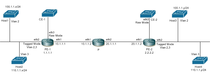
The following diagram illustrates the configuration steps in this section. In this sample, the VC host devices, Host1 and Host2, are connected to the Provider Edge (PE) router PE-1; and Host3 and Host4 are connected to PE-2. The VC is established between PE-1 and PE-2. Interface eth2, on PE-1 and PE-2, is connected to the customer network; eth1, on PE-1 and PE-2, is connected to the MPLS cloud.
MPLS Layer 2 Virtual Circuit
The VC configuration process can be divided into the following steps:
Note: Loopback addresses being used should be advertised through OSPF, or should be statically routed.
1. Configure the IP address and OSPF for the PE-1, P (Provider), and PE-2 routers.
2. Configure MPLS and LDP on PE-1, P, and PE-2, and LDP targeted peer for the PE-1 and PE-2 routers. (If RSVP is used for configuring trunks, LDP must be configured on PE-1 and PE-2, and RSVP must be configured on PE-1, P, and PE-2.)
3. Configure the VC.
4. Bind the customer interface to the VC.
Configure IP Address and OSPF on Routers
Configure the IP addresses and OSPF on the PE-1, P, and PE-2 routers.
PE-1
#configure terminal | Enter configure mode. |
(config)#interface lo | Specify the loopback interface (lo0) to be configured. |
(config-if)#ip address 1.1.1.1/32 secondary | Set the IP address of the loopback interface to 1.1.1.1/32. |
(config-if)#exit | Exit interface mode. |
(config)#interface eth1 | Specify the interface (eth1) to be configured. |
(config-if)#ip address 10.1.1.1/24 | Set the IP address of the interface to 10.1.1.1/24. |
(config-if)#exit | Exit interface mode. |
(config)#router ospf 100 | Configure the routing process and specify the Process ID (100). The Process ID should be a unique positive integer identifying the routing process. |
(config-router)#network 10.1.1.0/24 area 0 (config-router)#network 1.1.1.1/32 area 0 | Define the interface on which OSPF runs and associate the area ID (0) with the interface. |
P
#configure terminal | Enter configure mode. |
(config)#interface lo | Specify the loopback interface (lo0) to be configured. |
(config-if)#ip address 9.9.9.9/32 secondary | Set the IP address of the loopback interface to 9.9.9.9/32. |
(config-if)#exit | Exit interface mode. |
(config)#interface eth1 | Specify the interface (eth1) to be configured. |
(config-if)#ip address 10.1.1.2/24 | Set the IP address of the interface to 10.1.1.2/24. |
(config-if)#exit | Exit interface mode. |
(config)#interface eth2 | Specify the interface (eth2) to be configured. |
(config-if)#ip address 20.1.1.1/24 | Set the IP address of the interface to 20.1.1.1/24. |
(config-if)#exit | Exit interface mode. |
(config)#router ospf 100 | Configure the routing process and specify the Process ID (100). The Process ID should be a unique positive integer identifying the routing process. |
(config-router)#network 10.1.1.0/24 area 0 (config-router)#network 20.1.1.0/24 area 0 (config-router)#network 9.9.9.9/32 area 0 | Define the interface on which OSPF runs and associate the area ID (0) with the interface. |
PE-2
#configure terminal | Enter configure mode. |
(config)#interface lo | Specify the loopback interface (lo0) to be configured. |
(config-if)#ip address 2.2.2.2/32 secondary | Set the IP address of the loopback interface to 2.2.2.2/32. |
(config-if)#exit | Exit interface mode. |
(config)#interface eth1 | Specify the interface (eth1) to be configured. |
(config-if)#ip address 20.1.1.2/24 | Set the IP address of the interface to 20.1.1.2/24. |
(config-if)#exit | Exit interface mode. |
(config)#router ospf 100 | Configure the routing process and specify the Process ID (100). The Process ID should be a unique positive integer identifying the routing process. |
(config-router)#network 20.1.1.0/24 area 0 (config-router)#network 2.2.2.2/32 area 0 | Define the interface on which OSPF runs, and associate the area ID (0) with the interface. |
Configure MPLS, LDP, and LDP Targeted Peer on Routers
Configure MPLS and LDP on PE-1, P, and PE-2, and LDP targeted peers on PE-1 and PE-2.
Note: If RSVP is used for configuring trunks, LDP must be configured on PE-1 and PE-2, and RSVP must be configured on PE-1, P, and PE-2,
PE-1
#configure terminal | Enter configure mode. |
(config)#router ldp | Enter the Router mode. |
(config-router)#transport-address ipv4 1.1.1.1 | Configure the transport address to be used for a TCP session over which LDP will run on an IPv4 interface. |
(config-router)#targeted-peer ipv4 2.2.2.2 | Specify the targeted LDP peer on PE-1. |
(config-router-targeted-peer)# exit | Exit the Router targeted peer mode. |
(config-router)#exit | Exit the Router mode. |
(config)#interface eth1 | Specify the interface (eth1) to be configured. |
(config-if)#label-switching | Enable label switching on interface eth1. |
(config-if)#enable-ldp ipv4 | Enable LDP on interface eth1. |
P
#configure terminal | Enter configure mode. |
(config)#router ldp | Enter the Router mode. |
(config-router)#transport-address ipv4 9.9.9.9 | Configure the transport address to be used for a TCP session over which LDP will run on an IPv4 interface. |
(config-router)#exit | Exit the Router mode. |
(config)#interface eth1 | Specify the interface (eth1) to be configured. |
(config-if)#label-switching | Enable label switching on interface eth2. |
(config-if)#enable-ldp ipv4 | Enable LDP on interface eth2. |
(config-if)#exit | Exit interface mode. |
(config)#interface eth2 | Specify the interface (eth2) to be configured. |
(config-if)#label-switching | Enable label switching on interface eth2. |
(config-if)#enable-ldp ipv4 | Enable LDP on interface eth2. |
PE-2
#configure terminal | Enter configure mode. |
(config)#router ldp | Enter the Router mode. |
(config-router)#transport-address ipv4 2.2.2.2 | Configure the transport address to be used for a TCP session over which LDP will run on an IPv4 interface. |
(config-router)#targeted-peer ipv4 1.1.1.1 | Specify the targeted LDP peer on PE-2. |
(config-router-targeted-peer)# exit | Exit the Router targeted peer mode. |
(config-router)#exit | Exit the Router mode. |
(config)#interface eth1 | Specify the interface(eth1) to be configured. |
(config-if)#label-switching | Enable label switching on interface eth1. |
(config-if)#enable-ldp ipv4 | Enable LDP on interface eth1. |
Configure VC
Configure the VC. Each VC ID uniquely identifies the Layer-2 circuit among all the Layer-2 circuits.
Note: Both PE routers (endpoints) must be configured with the same VC-ID (100 in this example).
PE-1
#configure terminal | Enter configure mode. |
(config)#mpls l2-circuit t1 100 2.2.2.2 | Configure the VC for PE-2. In this example, t1 is the VC name, 100 is the VC ID, and 2.2.2.2 is the VC endpoint IP address. |
PE-2
#configure terminal | Enter configure mode. |
(config)#mpls l2-circuit t1 100 1.1.1.1 | Configure the VC for PE-1. In this example, t1 is the VC name, 100 is the VC ID, and 1.1.1.1 is the VC endpoint IP address. |
Bind Customer Interface to VC
Bind the customer interface to the VC using one of the two procedures described below: Layer-2 untagged traffic or Layer-2 tagged traffic.
Note: Layer 2 VCs can only be bound to Layer 2 interfaces. The VC encapsulation method should be Ethernet (default), VLAN.
Layer 2 Untagged Traffic
Use Access mode for Layer 2 untagged traffic.
PE-1
#configure terminal | Enter configure mode. |
(config)#service-template SUT1 | Create a service template SUT1 |
(config-svc)#match untagged | Allow untagged traffic. |
(config-svc)#exit | Exit the service template mode |
(config)#interface eth3 | Specify the interface (eth3) to be configured. |
(config-if)#switchport | Switch to Layer-2 mode. |
(config-if)#mpls-l2-circuit t1 service-template SUT1 | Bind the interface to the VC with service template. |
PE-2
#configure terminal | Enter configure mode. |
(config)#service-template SUT1 | Create a service template SUT1 |
(config-svc)#match untagged | Allow untagged traffic. |
(config-svc)#exit | Exit the service template mode |
(config)#interface eth3 | Specify the interface (eth3) to be configured. |
(config-if)#switchport | Switch to Layer-2 mode. |
(config-if)#mpls-l2-circuit t1 service-template SUT1 | Bind the interface to the VC with service template. |
Layer 2 Tagged Traffic
Use Trunk mode for Layer-2 tagged traffic. The following configuration allows only VLAN 2 and 3 traffic.
PE-1
#configure terminal | Enter configure mode. |
(config)#mpls l2-circuit t2 200 2.2.2.2 | Configure the VC for PE-2. In this example, t2 is the VC name, 200 is the VC ID, and 2.2.2.2 is the VC endpoint IP address. |
(config-pseudowire)#exit | Exit pseudowire config mode. |
(config)#service-template ST1 | Create a service template ST1 |
(config-svc)#match outer-vlan 2 | Allow VLAN 2 traffic on this VC. |
(config-svc)#match outer-vlan 3 | Allow VLAN 3 traffic on this VC. |
(config-svc)#exit | Exit the service template mode |
(config)#interface eth2 | Specify the interface (eth2) to be configured. |
(config-if)#switchport | Switch to Layer-2 mode. |
(config-if)#mpls-l2-circuit t2 service-template ST1 | Bind the interface to the VC with service template. |
PE-2
#configure terminal | Enter configure mode. |
(config)#mpls l2-circuit t2 200 1.1.1.1 | Configure the VC for PE-2. In this example, t2 is the VC name, 200 is the VC ID, and 1.1.1.1 is the VC endpoint IP address. |
(config-pseudowire)#exit | Exit pseudowire config mode. |
(config)#service-template ST1 | Create a service template ST1 |
(config-svc)#match outer-vlan 2 | Allow VLAN 2 traffic on this VC. |
(config-svc)#match outer-vlan 3 | Allow VLAN 3 traffic on this VC. |
(config-svc)#exit | Exit the service template mode |
(config)#interface eth2 | Specify the interface (eth2) to be configured. |
(config-if)#switchport | Switch to Layer-2 mode. |
(config-if)#mpls-l2-circuit t2 service-template ST1 | Bind the interface to the VC with service template. |
Validation
Use the show ldp mpls-l2-circuit (Control Plane) command, and the show mpls vc-table (Forwarding Plane) command, to display complete information about the Layer 2 VC.
If the VC State is UP in the output from the show ldp mpls-l2 circuit command, and the Status is Active in the output of the show mpls vc-table command, a ping from CE1 to CE2 should be successful.
#show ldp mpls-l2-circuit
Transport Client VC Trans Local Remote Destination
VC ID Binding State Type VC Label VC Label Address
100 eth3 UP Ethernet VLAN 24320 24321 2.2.2.2
200 eth2 UP Ethernet VLAN 24321 24322 2.2.2.2
#show mpls vc-table
VC-ID Vlan-ID Inner-Vlan-ID Access-Intf Network-Intf Out Label Tunnel-Label Nexthop Status
100 N/A N/A eth3 eth6 24321 24320 2.2.2.2 Active
200 N/A N/A eth2 eth6 24322 24320 2.2.2.2 Active
#
These additional commands can also be used to display information about the Layer 2 virtual circuits.
show ldp mpls-l2-circuit detail
show ldp mpls-l2-circuit VC-ID
show ldp mpls-l2-circuit VC-ID detail
show mpls l2-circuit
Configure a Static Layer-2 VC
For a static MPLS Layer 2 VC configuration:
1. Configure the VC with the manual option
2. Configure the VC FIB entry
3. Bind the VC; all steps are in the configurations that follow.
PE-1
#configure terminal | Enter configure mode. |
PE1(config)#mpls l2-circuit t3 300 2.2.2.2 manual | Configure the VC ID with the manual option (no signaling used). |
PE1(config-pseudowire)#exit | Exit pseudowire config mode. |
PE1(config)#service-template ST3 | Create a service template ST3 |
PE1(config-svc)#exit | Exit the service template mode |
PE1(config)#interface eth2 | Add an FTN entry; where 1000 is the incoming label, 2000 is the outgoing label, 2.2.2.2 is the endpoint, eth1 is the incoming interface name, and eth2 is outgoing interface name. |
PE1(config-if)#mpls-l2-circuit t2 service-template ST3 | Bind the interface to the VC with service template. |
PE1(config-if)#exit | Exit interface mode |
PE1(config)#mpls l2-circuit-fib-entry 300 1000 2000 2.2.2.2 eth1 eth2 | Configure the VC ID with the manual option (no signaling used). |
PE-2
#configure terminal | Enter configure mode. |
PE2(config)#mpls l2-circuit t3 300 1.1.1.1 manual | Configure the VC ID with the manual option (no signaling used). |
PE1(config-pseudowire)#exit | Exit pseudowire config mode. |
PE1(config)#service-template ST3 | Create a service template ST3 |
(config-svc)#exit | Exit the service template mode |
PE2(config)#interface eth2 | Add an FTN entry; where 2000 is the incoming label, 1000 is the outgoing label, 1.1.1.1 is the endpoint, eth1 is the incoming interface name, and eth 2 is outgoing interface name. |
PE2(config-if)#mpls-l2-circuit t2 service-template ST3 | Bind the interface to the VC with service template. |
PE2(config-if)#exit | Exit interface mode. |
PE2(config)#mpls l2-circuit-fib-entry 300 2000 1000 1.1.1.1 eth1 eth2 | Configure the VC ID with the manual option (no signaling used). |
PE2(config)#end | Exit configure mode |
Validation
This example shows number of configured VCs and its status.
#show mpls vc-table count
-------------------------------
Num PWs : 3
Active PWs : 3
OAM-only PWs : 0
Inactive PWs : 0
-------------------------------
#show ldp mpls-l2-circuit count
----------------------------------------------
Num Signaled PWs: 3 [UP: 3]
----------------------------------------------
Service template Configuration
PE-1
#configure terminal | Enter configure mode. |
(config)#mpls l2-circuit vc1 10 2.2.2.2 | Configure the VC |
(config-pseudowire)#service-tpid dot1.ad | Configure Service-TPID as dot1.ad (0x88a8) |
(config-pseudowire)#exit | Exit pseudowire config mode. |
(config)# service-template template1 | Configure the service template. |
(config-svc)# match double-tag outer-vlan 204 inner-vlan 203 | Matching criteria for service template. |
(config-svc)#rewrite ingress pop outgoing-tpid dot1.ad | Action performed for service template. |
(config-svc)#exit | Exit configure SVC mode |
(config)#interface eth2 | Specify the interface (eth2) to be configured. |
(config-if)#switchport | Switch to Layer-2 mode. |
(config-if)# switchport dot1q ethertype 0x88a8 | Configure interface ethertype as dot1.ad (0x88a8) |
(config-if)#mpls-l2-circuit vc1 service-template template1 | Bind the interface to the VC with service template. |
(config-if)#exit | End of Interface and configurations mode. |
PE-2
(config)#mpls l2-circuit vc1 10 1.1.1.1 | Configure the VC. |
(config-pseudowire)#service-tpid dot1.ad | Configure Service-TPID as dot1.ad (0x88a8) |
(config-pseudowire)#exit | Exit pseudowire config mode. |
(config)# service-template template1 | Configure the service template. |
(config-svc)# match double-tag outer-vlan 204 inner-vlan 203 | Matching criteria for service template. |
(config-svc)# rewrite ingress pop outgoing-tpid dot1.ad | Action performed for service template. |
(config-svc)#exit | Exit configure SVC mode |
(config)#interface eth2 | Specify the interface (eth2) to be configured. |
(config-if)#switchport | Switch to Layer-2 mode. |
(config-if)#switchport dot1q ethertype 0x88a8 | Configure interface ethertype as dot1.ad (0x88a8) |
(config-if)#mpls-l2-circuit vc1 service-template template1 | Bind the interface to the VC with service template. |
(config-if)#exit | End of interface and configurations mode. |
Validation
PE1
PE1#sh ldp mpls-l2-circuit detail
PW ID: 10, VC state is up
Access IF: eth2,up,AC state is up
Session IF: eth1, state is up
Destination: 2.2.2.2, Peer LDP Ident: 2.2.2.2
Local vctype: vlan, remote vctype :vlan
Local groupid: 0, remote groupid: 0
Local label: 24322, remote label: 52482
Local MTU: 1500, Remote MTU: 1500
Local Control Word: disabled Remote Control Word: Not-Applicable Current use: disabled
Local PW Status Capability : disabled
Remote PW Status Capability : disabled
Current PW Status TLV : disabled
PE1#sh mpls l2-circuit detail
MPLS Layer-2 Virtual Circuit: vc1, id: 10 PW-INDEX: 1 service-tpid: dot1.ad
Endpoint: 2.2.2.2
Control Word: 0
MPLS Layer-2 Virtual Circuit Group: none
Bound to interface: eth2
Virtual Circuit Type: Ethernet VLAN
Virtual Circuit is configured as Primary
Virtual Circuit is configured as Active
Virtual Circuit is active
Service-template : template1
Match criteria : 204/203
Action type : Pop
Outgoing tpid : dot1.ad
PE1#sh mpls vc-table
VC-ID Vlan-ID Inner-Vlan-ID Access-Intf Network-Intf Out Label Tunnel-Label Nexthop Status
10 N/A N/A eth2 eth1 52482 52480 2.2.2.2 Active
Service-template with multiple match support
This is to validate the multiple match criteria support in a service template. When multiple match statements are configured only rewrite push is supported, rewrite translate and pop are not supported.
PE-1
#configure terminal | Enter configure mode. |
(config)#mpls l2-circuit t4 400 2.2.2.2 | Configure the VC for PE-1. In this example, t4 is the VC name, 400 is the VC ID, and 2.2.2.2 is the VC endpoint IP address. |
(config-pseudowire)#exit | Exit pseudowire config mode. |
(config)#service-template template4 | Template configuration |
(config-svc)# match outer-vlan 700 | Allow VLAN 700 traffic on this VC |
(config-svc)# match double-tag outer-vlan 1200 inner-vlan 3200 | Allow double tag match with s+c tags |
(config-svc)# match untagged | Allow untagged traffic |
(config-svc)# rewrite ingress push 300 | Push Action performed for service template |
(config)#interface eth2 | Specify the interface (eth2) to be configured. |
(config-if)#switchport | Switch to Layer-2 mode. |
(config-if)#mpls-l2-circuit t4 service-template template4 | Bind the interface to the VC with service template. |
PE-2
#configure terminal | Enter configure mode. |
(config)#mpls l2-circuit t4 400 1.1.1.1 | Configure the VC for PE-2. In this example, t4 is the VC name, 400 is the VC ID, and 1.1.1.1 is the VC endpoint IP address. |
(config-pseudowire)#exit | Exit pseudowire config mode. |
(config)#service-template template4 | Template configuration |
(config-svc)# match outer-vlan 700 | Allow VLAN 700 traffic on this VC |
(config-svc)# match double-tag outer-vlan 1200 inner-vlan 3200 | Allow double tag match with s+c tags |
(config-svc)# match untagged | Allow untagged traffic |
(config-svc)# rewrite ingress push 300 | Push Action performed for service template |
(config)#interface eth2 | Specify the interface (eth2) to be configured. |
(config-if)#switchport | Switch to Layer-2 mode. |
(config-if)#mpls-l2-circuit t4 service-template template4 | Bind the interface to the VC with service template. |
Validation
PE1#sh ldp mpls-l2-circuit detail
PW ID: 400, VC state is up
Access IF: eth2,up,AC state is up
Session IF: eth1, state is up
Destination: 2.2.2.2, Peer LDP Ident: 2.2.2.2
Local vctype: vlan, remote vctype :vlan
Local groupid: 0, remote groupid: 0
Local label: 24324, remote label: 52485
Local MTU: 1500, Remote MTU: 1500
Local Control Word: disabled Remote Control Word: Not-Applicable Current use: disabled
Local PW Status Capability : disabled
Remote PW Status Capability : disabled
Current PW Status TLV : disabled
PE1#sh mpls l2-circuit detail
MPLS Layer-2 Virtual Circuit: t4, id: 400 PW-INDEX: 4 service-tpid: dot1.q
Endpoint: 2.2.2.2
Control Word: 0
MPLS Layer-2 Virtual Circuit Group: none
Bound to interface: eth2
Virtual Circuit Type: Ethernet VLAN
Virtual Circuit is configured as Primary
Virtual Circuit is configured as Active
Virtual Circuit is active
Service-template : template4
Match criteria : 700
1200/3200
untagged
Action type : Push
Action value : 300
PE1#show mpls vc-table
VC-ID Vlan-ID Inner-Vlan-ID Access-Intf Network-Intf Out Label Tunnel-Label Nexthop Status Ecmp-Group
400 N/A N/A eth2 eth1 24322 24320 2.2.2.2 Active N/A
PE2#show mpls vc-table
VC-ID Vlan-ID Inner-Vlan-ID Access-Intf Network-Intf Out Label Tunnel-Label Nexthop Status Ecmp-Group
400 N/A N/A eth2 eth1 24321 24325 1.1.1.1 Active N/A