MPLS OAM Configuration
This chapter contains configuration for MPLS Operations, Administration and Management (OAM).
Overview
MPLS OAM is used to detect forwarding plane failures in an MPLS network. Similar to ICMP echo requests and replies in an IP network, an MPLS network can use MPLS echo requests and replies for checking data plane and control plane operations in the Label Switched Path (LSP). The MPLS traceroute process also provides path details for the LSP.
Topology
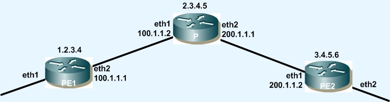
Topology for All Configurations
PE1
#configure terminal | Enter configure mode. |
(config)#interface lo | Enter interface mode for loopback. |
(config-if)#ip address 1.2.3.4/32 | Configure the loopback IP address. |
(config-if)#interface eth1 | Enter interface mode. |
(config-if)#ip address 100.1.1.1/24 | Configure the IP address for interface eth1. |
#exit | Exit interface mode. |
(config)#router ospf 100 | Configure OSPF. |
(config-router)#network 1.2.3.4/32 area 0 | Add loopback IP address to OSPF network. |
(config)-router#network 100.1.1.0/24 area 0 | Add eth1 IP address to OSPF network. |
P
#configure terminal | Enter configure mode. |
(config)#interface lo | Enter interface mode for loopback. |
(config-if)#ip address 2.3.4.5/32 | Configure the loopback IP address. |
(config-if)#interface eth1 | Enter interface mode. |
(config-if)#ip address 100.1.1.2/24 | Configure the IP address for interface eth1. |
(config-if)#interface eth2 | Enter interface mode. |
(config-if)#ip address 200.1.1.1/24 | Configure the IP address for interface eth2. |
#exit | Exit interface mode. |
(config)#router ospf 100 | Configure OSPF. |
(config-router)#network 2.3.4.5/32 area 0 | Add loopback IP address to OSPF network. |
(config)-router#network 100.1.1.0/24 area 0 | Add eth1 IP address to OSPF network. |
(config)-router#network 200.1.1.0/24 area 0 | Add eth2 IP address to OSPF network. |
PE2
#configure terminal | Enter configure mode. |
(config)#interface lo | Enter interface mode for loopback. |
(config-if)#ip address 3.4.5.6/32 | Configure the loopback IP address. |
(config-if)#interface eth1 | Enter interface mode. |
(config-if)#ip address 200.1.1.2/24 | Configure the IP address for interface eth2. |
#exit | Exit interface mode. |
(config)#router ospf 100 | Configure OSPF. |
(config-router)#network 3.4.5.6/32 area 0 | Add loopback IP address to OSPF network. |
(config)-router#network 200.1.1.0/24 area 0 | Add eth1 IP address to OSPF network. |
Validation
Router 1
#show ip ospf neighbor
OSPF process 100:
Neighbor ID Pri State Dead Time Address Interface InstanceID
2.3.4.5 1 Full/DR 00:00:37 100.1.1.2 eth2 0
Router 2
#show ip ospf neighbor
OSPF process 100:
Neighbor ID Pri State Dead Time Address Interface InstanceID
1.2.3.4 1 Full/Backup 00:00:37 100.1.1.1 eth1 0
3.4.5.6 1 Full/DR 00:00:34 200.1.1.2 eth2 0
Router 3
#show ip ospf neighbor
OSPF process 100:
Neighbor ID Pri State Dead Time Address Interface InstanceID
2.3.4.5 1 Full/DR 00:00:37 200.1.1.2 eth1 0
VCCV and BFD for Pseudowires
The Virtual Circuit Connectivity Verification (VCCV) mechanism is used to facilitate Operations Administration and Maintenance (OAM) in pseudowires (PW). VCCV defines a set of messages that are sent via a PW data stream to enable management functionalities, such as connectivity and verification. Each VCCV packet contains information about its sequence number and the current value of the transmission counter. When a PW receiver receives a VCCV packet, it records the transmission counter contained in the packet. Each PW receiver also has a local received counter, which counts received PW packets. The PW receiver compares the value of the transmission counter with that of the received counter. Packet losses are detected when the count of transmitted packets is greater than the count of received packets.
Bidirectional Forwarding Detection (BFD) is used as one of the connectivity verification mechanisms in VCCV when continuous monitoring is required for a session. BFD VCCV provides a detection mechanism for pseudowires as well as the OAM functions to use over a PW to check its true operational state.
CC Types
• Type 1: PWE3 Control Word with 0001b as first nibble
• Type 2: MPLS Router Alert Label
• Type 3: MPLS PW Label with TTL == 1
VCCV CV Types
• LSP Ping
BFD CV Types
• Type 1: BFD IP/UDP-encapsulated, for PW Fault Detection only
• Type 2: BFD IP/UDP-encapsulated, for PW Fault Detection and AC/PW Fault Status Signaling
• Type 3: BFD PW-ACH-encapsulated, for PW Fault Detection only
• Type 4: BFD PW-ACH-encapsulated, for PW Fault Detection and AC/PW Fault Status Signaling
VC with Control-word, VCCV and BFD Enabled
PE1
#configure terminal | Enter configure mode. |
(config)#router ldp | Enter the Router LDP mode. |
(config-router)#pw-status-tlv | Configure PW status TLV for PW status signaling. |
(config-router)#targeted-peer ipv4 3.4.5.6 | Configure targeted LDP session to PE2 loopback address. |
(config-router)#exit | Exit Router LDP mode and return to Configure mode. |
(config)#interface eth2 | Enter interface mode. |
(config-if)#label-switching | Configure label-switching on provider interface PE1. |
(config-if)#enable-ldp ipv4 | Enable LDP at provider interface PE1. |
(config-if)#exit | Exit interface mode. |
(config)#mpls l2-circuit test 100 3.4.5.6 | Configure PW named “test” with PW-ID 100. |
(config-pseudowire)#control-word | Enable Control-word. |
(config-pseudowire)#vccv cc-type type-1 | Enable VCCV CC-Type as 1. |
(config-pseudowire)#vccv cv-type type-3 | Enable VCCV CV-Type as 3. |
(config-pseduowire)#exit | Exit pseudowire mode. |
(config)#bridge 1 protocol ieee vlan-bridge | Specify VLAN for bridge 1. |
(config)#interface eth1 | Enter interface mode. |
(config-if)#switchport | Switch to Layer-2 mode. |
(config-if)#switchport mode access | Set the switching characteristics of this interface to Access mode. |
(config-if)#mpls-l2-circuit test | Bind the PW to access interface. |
(config-if)#exit | Exit interface mode. |
(config)#exit | Exit Configure mode. |
P
#configure terminal | Enter configure mode. |
(config)#router ldp | Enter the Router LDP mode. |
(config-router)#pw-status-tlv | Configure PW status TLV for PW status signaling. |
(config-router)#exit | Exit Router LDP mode. |
(config)#interface eth1 | Enter interface mode. |
(config-if)#label-switching | Configure label-switching for eth1. |
(config-if)#enable-ldp ipv4 | Enable LDP for eth1. |
(config-if)#exit | Exit interface mode. |
(config)#interface eth2 | Enter interface mode. |
(config-if)#label-switching | Configure label-switching for eth2. |
(config-if)#enable-ldp ipv4 | Enable LDP for eth2. |
(config-if)#exit | Exit interface mode. |
(config)#exit | Exit Configure mode. |
PE2
#configure terminal | Enter configure mode. |
(config)#router ldp | Enter the Router LDP mode. |
(config-router)#pw-status-tlv | Configure PW status TLV for PW status signaling. |
(config-router)#targeted-peer ipv4 1.2.3.4 | Configure targeted LDP session to PE1 loopback address. |
(config-router)#exit | Exit Router LDP mode. |
(config)#interface eth1 | Enter interface mode. |
(config-if)#label-switching | Configure label-switching on provider interface of PE2. |
(config-if)#enable-ldp ipv4 | Enable LDP on the provider interface of PE2. |
(config-if)#exit | Exit interface mode. |
(config)#mpls l2-circuit test 100 1.2.3.4 | Configure PW named “test” with PW-ID 100. |
(config-pseudowire)#control-word | Enable Control-word. |
(config-pseudowire)#vccv cc-type type-1 | Enable VCCV CC-Type as 1. |
(config-pseudowire)#vccv cv-type type-3 | Enable VCCV CV-Type as 3. |
(config-pseduowire)#exit | Exit pseudowire mode. |
(config)#bridge 1 protocol ieee vlan-bridge | Specify VLAN for bridge 1. |
(config)#interface eth1 | Enter interface mode. |
(config-if)#switchport | Switch to Layer-2 mode. |
(config-if)#switchport mode access | Set the switching characteristics of this interface to Access mode. |
(config-if)#mpls-l2-circuit test | Bind the PW to access interface. |
(config-if)#exit | Exit interface mode. |
(config)#exit | Exit Configure mode. |
Manual VC with VCCV and BFD Enabled
PE1
(config)#mpls vpls v1 100 | Configure VPLS v1 with id 100 on PE2. |
(config)#router ldp | Enter the Router LDP mode. |
(config-router)#pw-status-tlv | Configure PW status TLV for PW status signaling. |
(config-router)#targeted-peer ipv4 3.4.5.6 | Configure targeted LDP session to PE2 loopback address. |
(config-router)#exit | Exit Router LDP mode. |
(config)#interface eth2 | Enter interface mode. |
(config-if)#label-switching | Configure label-switching on provider interface of PE1. |
(config-if)#enable-ldp ipv4 | Enable LDP on the provider interface of PE1. |
(config-if)#exit | Exit interface mode. |
(config)#mpls l2-circuit test 100 3.4.5.6 | Configure PW named “test” with PW-ID 100. |
(config-pseudowire)#manual-pseudowire | Enable pseudowire. |
(config-pseudowire)#vccv cc-type type-1 | Enable VCCV CC-Type as 1. |
(config-pseudowire)#vccv cv-type type-3 | Enable VCCV CV-Type as 3. |
(config-pseduowire)#exit | Exit pseudowire mode. |
(config)#mpls l2-circuit-fib-entry 100 111 222 3.4.5.6 eth2 eth1 | Configure mpls-l2 circuit FIB entry for manual VC. |
(config)#bridge 1 protocol ieee vlan-bridge | Specify VLAN for bridge 1. |
(config)#interface eth1 | Enter interface mode. |
(config-if)#switchport | Switch to Layer-2 mode. |
(config-if)#switchport mode access | Set the switching characteristics of this interface to Access mode. |
(config-if)#mpls-l2-circuit test | Bind the PW to access interface. |
(config-if)#exit | Exit interface mode. |
(config)#exit | Exit Configure mode. |
P
#configure terminal | Enter configure mode. |
(config)#router ldp | Enter the Router LDP mode. |
(config-router)#pw-status-tlv | Configure PW status TLV for PW status signaling. |
(config-router)#exit | Exit Router LDP mode. |
(config)#interface eth1 | Enter interface mode. |
(config-if)#label-switching | Configure label-switching. |
(config-if)#enable-ldp ipv4 | Enable LDP. |
(config-if)#exit | Exit interface mode. |
(config)#interface eth2 | Enter interface mode. |
(config-if)#label-switching | Configure label-switching. |
(config-if)#enable-ldp ipv4 | Enable LDP. |
(config-if)#exit | Exit interface mode. |
(config)#exit | Exit Configure mode. |
PE2
#configure terminal | Enter configure mode. |
(config)#router ldp | Enter the Router LDP mode. |
(config-router)#pw-status-tlv | Configure PW status TLV for PW status signalling. |
(config-router)#targeted-peer ipv4 1.2.3.4 | Configure targeted LDP session to PE1 loopback address. |
(config-router)#exit | Exit Router LDP mode. |
(config)#interface eth1 | Enter interface mode. |
(config-if)#label-switching | Configure label-switching on provider interface of PE2. |
(config-if)#enable-ldp ipv4 | Enable LDP on the provider interface of PE2. |
(config-if)#exit | Exit interface mode. |
(config)#mpls l2-circuit test 100 3.4.5.6 | Configure PW named “test” with PW-ID 100. |
(config-pseudowire)#manual-pseudowire | Enable pseudowire. |
(config-pseudowire)#vccv cc-type type-1 | Enable VCCV CC-Type as 1. |
(config-pseudowire)#vccv cv-type type-3 | Enable VCCV CV-Type as 3. |
(config-pseduowire)#exit | Exit pseudowire mode. |
(config)#mpls l2-circuit-fib-entry 100 222 111 1.2.3.4 eth2 eth1 | Configure mpls-l2 circuit FIB entry for the manual VC. |
(config)#bridge 1 protocol ieee vlan-bridge | Specify the VLAN for bridge 1. |
(config)#interface eth2 | Enter interface mode. |
(config-if)#switchport | Switch to Layer-2 mode. |
(config-if)#switchport mode access | Set the switching characteristics of this interface to Access mode. |
(config-if)#mpls-l2-circuit test | Bind the PW to access interface. |
(config-if)#exit | Exit interface mode. |
(config)#exit | Exit Configure mode. |
Remove VCCV Configuration
PE1
#configure terminal | Enter configure mode. |
(config)#no mpls l2-circuit test 100 3.4.5.6 control-word manual | Remove VC named “test”. |
(config)#exit | Exit Configure mode. |
PE2
#configure terminal | Enter configure mode. |
(config)#no mpls l2-circuit test 100 1.2.3.4 control-word manual | Remove VC named “test”. |
(config)#exit | Exit Configure mode. |
Validation
Enter the commands listed in the section below.
Verify BFD Session On PE1
#show bfd session detail
-------------------------------------------
Session Interface Index: 4 Session Index: 1
Lower Layer: MPLS VCCV Version : 1 Session Type: Single Hop
Session State : Up
Local Discriminator : 1 Remote Discriminator: 1
VC ID: 100 Incoming VC Label: 53120
Local Address : 1.2.3.4/32 Remote Address: 127.0.0.12/32
Local Port : 49152 Remote Port: 3784
Options :
Diagnostics: None
Timers in Milliseconds
Min Tx: 20 Min Rx: 20 Multiplier: 5
Min echo Rx: 10 Neg Tx: 20
Neg echo intrvl: 10 Neg detect mult: 5
Storage type: 0
Last sess down time: 00:00:00
Sess discontinue time: 00:00:00
Counters values:
Pkt In 000000000001ef3a Pkt Out 0000000000000000
Echo Out 0000000000000000
IPv6 Pkt In 0000000000000000 IPv6 Pkt Out 0000000000000000
IPv6 Echo Out 0000000000000000
UP Count: 1 UPTIME: 00:40:26
NSM-> Client ID: 1 Flags: 4
Number of Sessions: 1
Verify VCCV and BFD CV Types in Use
#show mpls l2-circuit
MPLS Layer-2 Virtual Circuit: test, id: 100 PW-INDEX: 1
Endpoint: 3.4.5.6
Control Word: 1
MPLS Layer-2 Virtual Circuit Group: none
Bound to interface: eth1
Virtual Circuit Type: Ethernet VLAN
Virtual Circuit is configured as Primary
Virtual Circuit is configured as Active
Virtual Circuit runtime mode is active
Local VCCV Capability:
CC-Types: Type 1(in use) Type 2 Type 3
CV-Types:
LSP ping(in use) BFD IP/UDP-encapsulated, for PW Fault Detection only
BFD IP/UDP-encapsulated, for PW Fault Detection and AC/PW Fault Status Signaling
BFD PW-ACH-encapsulated, for PW Fault Detection only
BFD PW-ACH-encapsulated, for PW Fault Detection and AC/PW Fault Status Signaling (in use)
Verify VCCV Ping on PE1
#ping mpls l2-circuit vccv 100 force-explicit-null detail
Sending 5 MPLS Echos to VC Id : 100, timeout is 5 seconds
Codes:
'!' - Success, 'Q' - request not sent, '.' - timeout,
'x' - Retcode 0, 'M' - Malformed Request, 'm' - Errored TLV,
'N' - LBL Mapping Err, 'D' - DS Mismatch,
'U' - Unknown Interface, 'R' - Transit (LBL Switched),
'B' - IP Forwarded, 'F' No FEC Found, 'f' - FEC Mismatch,
'P' - Protocol Error, 'X' - Unknown code
Type 'Ctrl+C' to abort
! seq_num = 1 3.4.5.6 0.54 ms
! seq_num = 2 3.4.5.6 2.36 ms
! seq_num = 3 3.4.5.6 0.47 ms
! seq_num = 4 3.4.5.6 2.22 ms
! seq_num = 5 3.4.5.6 0.49 ms
Success Rate is 100.00 percent (5/5)
round-trip min/avg/max = 0.47/1.42/2.36