PW Redundancy Configuration
This chapter contains configurations for Pseudowire Redundancy. It also provides an overview of Pseudowire concepts.
Overview
In a single-segment pseudowire (SS-PW) application, the PSN (packet switched network) layer usually provides protection for the PW. One way is by using an RSVP LSP with FRR (Fast Reroute) backup; another way is an end-to-end backup LSP (Label Switched Path). However, there are some applications where the backup PW terminates on a different target PE node, so PSN protection methods cannot protect against failure of either the target PE (provider edge) node or a remote Access Circuit (AC). It is also important to an operator that a particular PW is preferred, for example, the one with the least latency.
PW redundancy supports Label Distribution Protocol (LDP) PW and manual switchover between primary PW and secondary PW in MTU-s. In the case of PW applications, the PSN layer can provide the protection for PW. Occasionally, a TE (traffic-engineered) LSP signaled by RSVP-TE can be used as a PSN tunnel for a PW. In this scenario, TE can provide FRR to protect the end-to-end LSP in the PSN layer.
FRR-based protection schemes cannot protect against failure of PE nodes and access circuits. However, PW redundancy can protect against these failures. Multi-homed CE (customer edge) devices can be connect between two PE nodes through two access circuits to provide protection. In case of Hierarchical VPLS (HVPLS), the MTU-s can create spoke circuits at the PEs. Any one can be used to protect another.
Topology
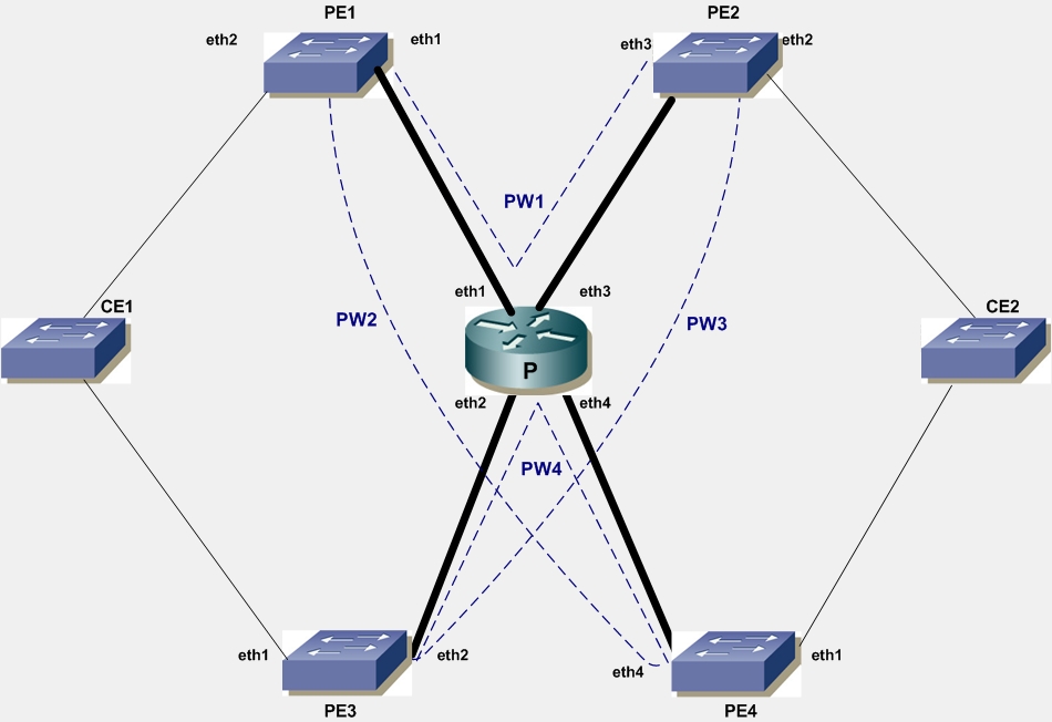
The diagram depicts two multi-homed CE devices, CE1 and CE2, connected to two PE devices each, PE1 and PE3, and PE2 and PE4, respectively. In this scenario, multiple single-segment Ethernet pseudowires need to be signaled: PW1 between PE1 and PE2; PW2 between PE1 and PE4; PW3 between PE2 and PE3; and PW4 between PE3 and PE4.
Dual-Homed CE Devices for Ethernet Pseudowires
PE1
#configure terminal | Enter configure mode. |
(config-if)#interface lo | Identify the loopback interface to configure (lo). |
(config-if)#ip address 66.66.66.66/32 | Set the IP address of the loopback interface to 66.66.66.66/32. |
(config-if)#exit | Exit interface mode |
(config)#interface eth1 | Enter interface mode. |
(config-if)#label-switching | Enable label switching on the interface. |
(config-if)#ip address 11.0.0.66/24 | Set the IP address of the interface to 11.0.0.66/24. |
(config-if)#exit | Exit interface mode. |
(config)#router ospf | Enter the Router OSPF mode. |
(config-router)#network 11.0.0.0/24 area 0 (config-router)#network 66.66.66.66/32 area 0 | Define the Network on which OSPF runs and associate the area ID (area 0) with the interface. |
(config-router)#exit | Exit Router mode and return to Configure mode. |
(config)#router ldp | Enter the Router mode for LDP. |
(config-router)#transport-address ipv4 66.66.66.66 | Configure loopback address as LDP transport address. |
(config-router)#pw-status-tlv | Enable the PW Status TLV (pw-status-tlv). |
(config-router)#targeted-peer-ipv4 68.68.68.68 | Configure LDP targeted peer to PE2. |
(config-router)#targeted-peer-ipv4 69.69.69.69 | Configure LDP targeted peer to PE4. |
(config-router)#exit | Exit Router mode and return to Configure mode. |
(config)#interface eth1 | Enter interface mode. |
(config-if)#enable-ldp ipv4 | Enable IPv4 LDP on the interface. |
(config-if)#exit | Exit interface mode. |
(config)#mpls l2-circuit vc1 10 68.68.68.68 | Configure a Virtual Circuit for PE1. In this example, vc1 is the VC name, 10 is the VC ID, and 68.68.68.68 is the endpoint IP address. |
(config-pseduowire)#exit | Exit pseudowire mode. |
(config)#mpls l2-circuit vc2 20 69.69.69.69 | Configure another Virtual Circuit for PE1. In this example, vc2 is the VC name, 20 is the VC ID, and 69.69.69.69 is the endpoint IP address. |
(config-pseduowire)#exit | Exit pseudowire mode. |
(config-if)#interface eth2 | Enter interface mode. |
(config-if)#switchport | Switch to Layer 2 mode. |
(config-if)#mpls-l2-circuit vc1 ethernet | Bind VC1 as an Ethernet circuit. |
(config-if)#mpls-l2-circuit vc2 ethernet | Bind VC2 as an Ethernet circuit. |
(config-if)#exit | Exit interface mode. |
PE2
#configure terminal | Enter configure mode. |
(config-if)#interface lo | Identify the loopback interface to configure (lo). |
(config-if)#ip address 68.68.68.68/24 | Set the IP address of the loopback interface to 68.68.68.68/24. |
(config-if)#exit | Exit interface mode. |
(config)#interface eth3 | Enter interface mode. |
(config-if)#label switching | Enable label switching on the interface. |
(config-if)#ip address 33.0.0.68/24 | Set the IP address of the interface to 33.0.0.68/24. |
(config-if)#exit | Exit interface mode. |
(config)#router ospf | Enter the Router mode for OSPF. |
(config-router)#network 68.68.68.68/32 area 0 (config-router)#network 33.0.0.0/24 area 0 | Define the Network on which OSPF runs and associate the area ID (area 0) with the interface. |
(config-router)#exit | Exit Router mode and return to Configure mode. |
(config)#router ldp | Enter the Router mode for LDP. |
(config-router)#transport-address ipv4 68.68.68.68 | Configure loopback address as LDP transport address. |
(config-router)#pw-status-tlv | Enable the PW Status TLV (pw-status-tlv). |
(config-router)#targeted-peer-ipv4 66.66.66.66 | Configure LDP targeted peer to PE1. |
(config-router)#targeted-peer-ipv4 67.67.67.67 | Configure LDP targeted peer to PE3. |
(config-router)#exit | Exit Router mode and return to Configure mode. |
(config)#interface eth3 | Enter interface mode. |
(config-if)#enable-ldp ipv4 | Enable IPv4 LDP on the interface. |
(config-if)#exit | Exit interface mode. |
(config)#mpls l2-circuit vc1 10 66.66.66.66 | Configure a Virtual Circuit for PE2. In this example, vc1 is the VC name, 10 is the VC ID, and 66.66.66.66 is the endpoint IP address. |
(config-pseduowire)#exit | Exit pseudowire mode. |
(config)#mpls l2-circuit vc2 20 67.67.67.67 | Configure another Virtual Circuit for PE2. In this example, vc2 is the VC name, 20 is the VC ID, and 67.67.67.67 is the endpoint IP address. |
(config-pseduowire)#exit | Exit pseudowire mode. |
(config-if)#interface eth2 | Enter interface mode. |
(config-if)#switchport | Switch to Layer 2 mode. |
(config-if)#mpls-l2-circuit vc1 ethernet | Bind VC1 as an Ethernet circuit. |
(config-if)#mpls-l2-circuit vc2 ethernet | Bind VC2 as an Ethernet circuit. |
(config-if)#exit | Exit interface mode. |
PE3
#configure terminal | Enter configure mode. |
(config-if)#interface lo | Identify the loopback interface to configure (lo). |
(config-if)#ip address 67.67.67.67/32 | Set the IP address of the loopback interface to 67.67.67.67/32. |
(config-if)#exit | Exit interface mode. |
(config)#interface eth2 | Enter interface mode. |
(config-if)#label-switching | Enable label switching on the interface. |
(config-if)#ip address 22.0.0.67/24 | Set the IP address of the interface to 22.0.0.67/24. |
(config-if)#exit | Exit interface mode. |
(config)#router ospf | Enter the Router mode for OSPF. |
(config-router)#network 67.67.67.67/32 area 0 (config-router)#network 22.0.0.0/24 area 0 | Define the Network on which OSPF runs and associate the area ID (area 0) with the interface. |
(config-router)#exit | Exit Router mode and return to Configure mode. |
(config)#router ldp | Enter the Router mode for LDP. |
(config-router)#transport-address ipv4 67.67.67.67 | Configure loopback address as LDP transport address. |
(config-router)#pw-status-tlv | Enable the PW Status TLV (pw-status-tlv). |
(config-router)#targeted-peer-ipv4 68.68.68.68 | Configure LDP targeted peer for PE2. |
(config-router)#targeted-peer-ipv4 69.69.69.69 | Configure LDP targeted peer for PE4. |
(config-router)#exit | Exit Router mode and return to Configure mode. |
(config)#interface eth2 | Enter interface mode. |
(config-if)#enable-ldp ipv4 | Enable IPv4 LDP on the interface. |
(config-if)#exit | Exit interface mode. |
(config)#mpls l2-circuit vc3 30 68.68.68.68 | Configure a Virtual Circuit for PE3. In this example, vc3 is the VC name, 30 is the VC ID, and 68.68.68.68 is the endpoint IP address. |
(config-pseduowire)#exit | Exit pseudowire mode. |
(config)#mpls l2-circuit vc4 40 69.69.69.69 | Configure another Virtual Circuit for PE3. In this example, vc4 is the VC name, 40 is the VC ID, and 69.69.69.69 is the endpoint IP address. |
(config-pseduowire)#exit | Exit pseudowire mode. |
(config-if)#interface eth1 | Enter interface mode. |
(config-if)#switchport | Switch to Layer 2 mode. |
(config-if)#mpls-l2-circuit vc1 ethernet | Bind VC3 as an Ethernet circuit. |
(config-if)#mpls-l2-circuit vc2 ethernet | Bind VC4 as an Ethernet circuit. |
(config-if)#vc-mode standby | Configure VC mode as standby. |
(config-if)#exit | Exit interface mode. |
PE4
#configure terminal | Enter configure mode. |
(config-if)#interface lo | Identify the loopback interface to configure (lo). |
(config-if)#ip address 69.69.69.69/32 | Set the IP address of the loopback interface to 69.69.69.69/32. |
(config-if)#exit | Exit interface mode. |
(config)#interface eth4 | Enter interface mode. |
(config-if)#label-switching | Enable label switching on the interface. |
(config-if)#ip address 44.0.0.69/24 | Set the IP address of the interface to 44.0.0.69/24. |
(config-if)#exit | Exit interface mode. |
(config)#router ospf | Enter the Router mode for OSPF. |
(config-router)#network 69.69.69.69/32 area 0 (config-router)#network 44.0.0.0/24 area 0 | Define the Network on which OSPF runs and associate the area ID (area 0) with the interface. |
(config-router)#exit | Exit Router mode and return to Configure mode. |
(config)#router ldp | Enter the Router mode for LDP. |
(config-router)#transport-address ipv4 69.69.69.69 | Configure LDP loopback address as transport address. |
(config-router)#pw-status-tlv | Enable the Pseudowire Status TLV (pw-status-tlv). |
(config-router)#targeted-peer-ipv4 68.68.68.68 | Configure LDP targeted peer to PE1. |
(config-router)#targeted-peer-ipv4 69.69.69.69 | Configure LDP targeted peer to PE3. |
(config-router)#exit | Exit the Router mode and return to Configure mode. |
(config)#interface eth4 | Enter interface mode. |
(config-if)#enable-ldp ipv4 | Enable IPv4 LDP on the interface. |
(config-if)#exit | Exit interface mode. |
(config)#mpls l2-circuit vc2 20 66.66.66.66 | Configure a Virtual Circuit for PE1. In this example, vc2 is the VC name, 20 is the VC ID, and 66.66.66.66 is the endpoint IP address. |
(config-pseduowire)#exit | Exit pseudowire mode. |
(config)#mpls l2-circuit vc4 40 67.67.67.67 | Configure another Virtual Circuit for PE3. In this example, vc4 is the VC name, 40 is the VC ID, and 66.66.66.66 is the endpoint IP address. |
(config-pseduowire)#exit | Exit pseudowire mode. |
(config-if)#interface eth1 | Enter interface mode. |
(config-if)#switchport | Switch to Layer 2 mode. |
(config-if)#mpls-l2-circuit vc2 ethernet | Bind VC2 as an Ethernet circuit. |
(config-if)#mpls-l2-circuit vc3 ethernet | Bind VC4 as an Ethernet circuit. |
(config-if)#vc-mode standby | Configure VC mode as standby. |
(config-if)#exit | Exit interface mode. |
P
#configure terminal | Enter configure mode. |
(config-if)#interface lo | Identify the loopback interface to configure (lo). |
(config-if)#ip address 71.71.71.71 | Set the IP address of the loopback interface to 71.71.71.71. |
(config-if)#exit | Exit interface mode. |
(config)#router ldp | Enter the Router mode for LDP. |
(config-router)#transport-address ipv4 71.71.71.71 | Configure loopback address as LDP transport address. |
(config-router)#pw-status-tlv | Enable the PW Status TLV (pw-status-tlv). |
(config-router)#exit | Exit Router mode and return to Configure more. |
(config)#interface eth1 | Enter interface mode. |
(config-if)#ip address 11.0.0.71/24 | Set the IP address of eth0 to 11.0.0.71/24. |
(config-if)#exit | Exit interface mode. |
(config)#interface eth2 | Enter interface mode. |
(config-if)#label-switching | Enable label switching on interface eth1. |
(config-if) ip address 22.0.0.71/24 | Set the IP address of the interface to 22.0.0.71/24. |
(config-if)#enable-ldp ipv4 | Enable IPv4 LDP on the interface. |
(config-if)#exit | Exit interface mode. |
(config)#interface eth3 | Enter interface mode. |
(config-if)#label-switching | Enable label switching on the interface. |
(config-if)#ip address 33.0.0.71/24 | Set the IP address for the interface to 33.0.0.71/24. |
(config-if)#enable-ldp ipv4 | Enable IPv4 LDP on the interface. |
(config-if)#exit | Exit interface mode. |
(config)#interface eth4 | Enter interface mode. |
(config-if)#label-switching | Enable label switching on the interface. |
(config-if)#ip address 44.0.0.71/24 | Set the IP address for the interface to 44.0.0.71/24. |
(config-if) enable-ldp ipv4 | Enable IPv4 LDP on the interface. |
(config-if)#exit | Exit interface mode. |
(config)#router ospf | Enter the Router mode for OSPF. |
(config-router)#network 11.0.0.0/24 area 0 (config-router)#network 22.0.0.0/24 area 0 (config-router)#network 33.0.0.0/24 area 0 (config-router)#network 44.0.0.0/24 area 0 (config-router)#network 71.71.71.71/32 area 0 | Configure the Network associations for router P and associate them all with area 0. |
(config-router)#exit | Exit Router mode and return to Configure mode. |
Validation
To see summary information about the Virtual Circuits, use the following command:
#show mpls vc-table
The samples below show summary information about the just-configured four virtual circuits.
QA66#show mpls vc-table
VC-ID Vlan-ID Access-Intf Network-Intf Out Label Tunnel-Label Nexthop Status
10 N/A eth2 eth1 52488 52482 68.68.68.68 Active
20 N/A eth2 eth1 52480 52484 69.69.69.69 Standby
QA67#show mpls vc-table
VC-ID Vlan-ID Access-Intf Network-Intf Out Label Tunnel-Label Nexthop Status
30 N/A eth1 eth2 52488 52485 68.68.68.68 Standby
40 N/A eth1 eth2 52487 52481 69.69.69.69 Standby
To view detailed configuration information about the L2 Virtual Circuits, including LDP PW status, use the following command:
#show lpd mpls-l2-circuit detail
An example of the output of this command follows:
QA66#show ldp mpls-l2-circuit detail
vcid: 10, type: ethernet, local groupid: 4, remote groupid: 4 (vc is up)
destination: 68.68.68.68, Peer LDP Ident: 68.68.68.68
Local label: 52480, remote label: 52488
Access IF: eth2, Network IF: eth1
Local MTU: 1500, Remote MTU: 1500
Local Control Word: disabled, Remote Control Word: disabled, Current use: disabled
Local PW Status Capability : enabled
Remote PW Status Capability : enabled
Current PW Status TLV : enabled
Local PW Status :
Forwarding
Active
Remote PW Status :
Forwarding
Active
vcid: 20, type: ethernet, local groupid: 4, remote groupid: 3 (vc is up)
destination: 69.69.69.69, Peer LDP Ident: 69.69.69.69
Local label: 52481, remote label: 52480
Access IF: eth2, Network IF: eth1
Local MTU: 1500, Remote MTU: 1500
Local Control Word: disabled, Remote Control Word: disabled, Current use: disabled
Local PW Status Capability : enabled
Remote PW Status Capability : enabled
Current PW Status TLV : enabled
Local PW Status :
Not Forwarding
Active
Remote PW Status :
Not Forwarding
Standby
Virtual Circuit PW Configuration
To view configuration information about the L2 Virtual Circuits, use the following command:
#show mpls l2-circuit
An sample of the output of this command follows:
MPLS Layer-2 Virtual Circuit: vc1, id: 10
Endpoint: 68.68.68.68
Control Word: 0
MPLS Layer-2 Virtual Circuit Group: none
Bound to interface: eth2
Virtual Circuit Type: Ethernet
Virtual Circuit is configured as Primary
Virtual Circuit is configured as Active
Virtual Circuit runtime mode is Active
MPLS Layer-2 Virtual Circuit: vc2, id: 20
Endpoint: 69.69.69.69
Control Word: 0
MPLS Layer-2 Virtual Circuit Group: none
Bound to interface: eth2
Virtual Circuit Type: Ethernet
Virtual Circuit is configured as Primary
Virtual Circuit is configured as Active
Virtual Circuit runtime mode is Active
MTU-s with Redundant Spoke Circuits
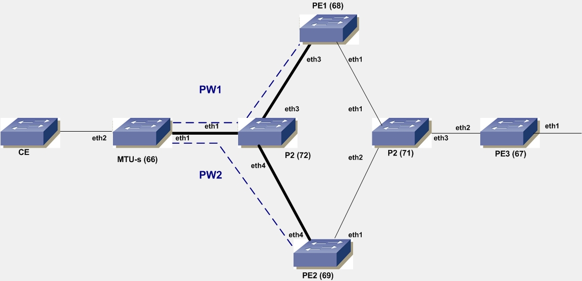
In this scenario, MTU-s has redundant spoke circuits PW1 and PW2 connected to PE1 and PE2, respectively. User should configure MTU-s so that one PW is Primary and the other as Secondary. With P1 designated as Primary and PW2 designated as Secondary, MTU-s announces that PW1 is in the Active mode and PW2 is in the Standby mode. If PW1 fails, MTU-s performs a switchover by announcing PW2 as Active and PW1 as Standby.
MTUs with Redundant Spoke Circuits
MTU-s
#configure terminal | Enter configure mode. |
(config-if)#lo | Identify the loopback interface to configure (lo). |
(config-if)#ip address 66.66.66.66/32 | Set the IP address of the loopback interface to 66.96.66.66/32. |
(config-if)#exit | Exit interface mode. |
(config)#interface eth1 | Enter interface mode. |
(config-if)#label-switching | Enable label switching on the interface. |
(config-if)#ip address 11.0.0.66/24 | Set the IP address of the interface to 11.1.1.66./24. |
(config-if)#exit | Exit interface mode. |
(config)#router ospf | Enter the Router mode for OSPF. |
(config-router)#network 66.66.66.66/32 area 0 (config-router)#network 11.0.0.66/24 area 0 | Define the Network on which OSPF runs and associate the area ID (area 0) with the interface. |
(config-router)#exit | Exit Router mode and return to Configure mode. |
(config)#router ldp | Enter the Router mode for LDP. |
(config-router)#transport-address ipv4 66.66.66.66 | Configure loopback address as LDP transport address. |
(config-router)#pw-status-tlv | Enable the PW Status TLV (pw-status-tlv). |
(config-router)#targeted-peer-ipv4 68.68.68.68 | Configure LDP targeted peer to PE1. |
(config-router)#targeted-peer-ipv4 69.69.69.69 | Configure LDP targeted peer to PE2. |
(config-router)#exit | Exit Router mode and return to Configure mode. |
(config)#interface eth1 | Enter interface mode. |
(config-if)#enable-ldp ipv4 | Enable IPv4 LDP on the interface. |
(config-if)#exit | Exit interface mode. |
(config)#mpls l2-circuit vc1 10 68.68.68.68 | Configure a Virtual Circuit to PE1. In this example, vc1 is the VC name, 10 is the VC ID, and 68.68.68.68 is the endpoint IP address. |
(config-pseduowire)#exit | Exit pseudowire mode. |
(config)#mpls l2-circuit vc2 20 69.69.69.69 | Configure another Virtual Circuit to PE1. In this example, vc2 is the VC name, 20 is the VC ID, and 69.69.69.69 is the endpoint IP address. |
(config-pseduowire)#exit | Exit pseudowire mode. |
(config-if)#interface eth2 | Enter interface mode. |
(config-if)#switchport | Switch to Layer 2 mode. |
(config-if)#mpls-l2-circuit vc1 ethernet | Bind VC1 as an Ethernet circuit. |
(config-if)#mpls-l2-circuit vc2 ethernet secondary | Bind VC2 as secondary. |
(config-if)#exit | Exit interface mode. |
P1
#configure terminal | Enter configure mode. |
(config-if)#interface lo | Identify the loopback interface to configure (lo). |
(config-if)#ip address 71.71.71.71 | Set the IP address of the loopback interface to 71.71.71.71. |
(config-if)#exit | Exit interface mode. |
(config)#router ldp | Enter the Router mode for LDP. |
(config-router)#transport-address ipv4 71.71.71.71 | Configure loopback address as LDP transport address. |
(config-router)#pw-status-tlv | Enable the PW Status TLV (pw-status-tlv). |
(config-router)#exit | Exit Router mode and return to Configure mode. |
(config)#interface eth1 | Enter interface mode. |
(config-if)#label-switching | Enable label switching on the interface. |
(config-if)#ip address 11.0.0.71/24 | Set the IP address of eth1 to 11.0.0.71/24. |
(config-if)#enable-ldp ipv4 | Enable IPv4 LDP on the interface. |
(config-if)#exit | Exit interface mode. |
(config)#interface eth3 | Enter interface mode. |
(config-if)#label-switching | Enable label switching on the interface. |
(config-if)#ip address 33.0.0.71/24 | Set the IP address for eth3 to 33.0.0.71/24. |
(config-if)#enable-ldp ipv4 | Enable IPv4 LDP on the interface. |
(config-if)#exit | Exit interface mode. |
(config)#interface eth4 | Enter interface mode. |
(config-if)#label-switching | Enable label switching on the interface. |
(config-if)#ip address 44.0.0.71/24 | Set the IP address for the interface to 44.0.0.71/24. |
(config-if)#enable-ldp ipv4 | Enable IPv4 LDP on the interface. |
(config-if)#exit | Exit interface mode. |
(config)#router ospf | Enter the Router mode for OSPF. |
(config-router)#network 71.71.71.71/32 area 0 (config-router)#network 11.0.0.71/24 area 0 (config-router)#network 33.0.0.71/24 area 0 (config-router)#network 44.0.0.71/24 area 0 | Configure the Network associations for router P1 and associate them all to area0. |
(config-router)#exit | Exit Router mode and return to Configure mode. |
Configure PE1
#configure terminal | Enter configure mode. |
(config-if)#interface lo | Identify the loopback interface to configure (lo). |
(config-if)#ip address 68.68.68.68/32 | Set the IP address of the loopback interface to 68.68.68.68/32. |
(config-if)#exit | Exit interface mode. |
(config)#interface eth3 | Enter interface mode. |
(config-if)#label-switching | Enable label switching on the interface. |
(config-if)#ip address 33.0.0.68/24 | Set the IP address of the interface to 33.0.0.68/24. |
(config-if)#exit | Exit interface mode. |
(config)#interface eth1 | Enter interface mode. |
(config-if)#label-switching | Enable label switching on the interface. |
(config-if)#ip address 22.0.0.68/24 | Set the IP address of the interface to 22.0.0.68/24. |
(config-if)#exit | Exit interface mode. |
(config)#router ospf | Enter the Router mode for OSPF. |
(config-router)#network 68.68.68.68/32 area 0 (config-router)#network 33.0.0.0/24 area 0 (config-router)#network 22.0.0.0/24 area 0 | Define the Network on which OSPF runs and associate the area ID (area 0) with the interfaces. |
(config-router)#exit | Exit Router mode and return to Configure mode. |
(config)#router ldp | Enter the Router mode for LDP. |
(config-router)#transport-address ipv4 68.68.68.68 | Configure loopback address as LDP transport address. |
(config-router)#pw-status-tlv | Enable the PW Status TLV (pw-status-tlv). |
(config-router)#targeted-peer-ipv4 66.66.66.66 | Configure LDP targeted peer to MTU-s. |
(config-router)#targeted-peer-ipv4 67.67.67.67 | Configure LDP targeted peer to PE3. |
(config-router)#exit | Exit Router mode and return to Configure mode. |
(config)#interface eth3 | Enter interface mode. |
(config-if)#enable-ldp ipv4 | Enable IPv4 LDP on the interface. |
(config-if)#exit | Exit interface mode. |
(config)#interface eth1 | Enter interface mode. |
(config-if)#enable-ldp ipv4 | Enable IPv4 LDP on the interface. |
(config-if)#exit | Exit interface mode. |
(config)#mpls l2-circuit vc1 10 66.66.66.66 | Configure a Virtual Circuit to MTU-s. In this example, vc1 is the VC name, 10 is the VC ID, and 66.66.66.66 is the endpoint IP address. |
(config-pseduowire)#exit | Exit pseudowire mode. |
(config)#mpls vpls vp1 15 | Enter VPLS mode and configure VPLS vp1 with VPLS ID 15. |
(config-vpls)#signaling ldp | Enter VPLS signaling LDP mode. |
(config-vpls-sig)#vpls-peer 67.67.67.67 | Configure a VPLS mesh peer to PE3. |
(config-vpls-sig)#exit | Exit signaling LDP mode. |
(config-vpls)#vpls-vc vc1 | Configure vc1 as a VPLS spoke peer. |
(config-vpls)#exit | Exit interface mode. |
Configure PE2
#configure terminal | Enter configure mode. |
(config-if)#interface lo | Identify the loopback interface to configure (lo). |
(config-if)#ip address 69.69.69.69/32 | Set the IP address of the loopback interface to 69.69.69.69/32. |
(config-if)#exit | Exit interface mode. |
(config)#interface eth4 | Enter interface mode. |
(config-if)#label-switching | Enable label switching on the interface. |
(config-if)#ip address 44.0.0.69/24 | Set the IP address of the interface to 44.0.0.69/24. |
(config-if)#exit | Exit interface mode. |
(config)#interface eth1 | Enter interface mode. |
(config-if)#label-switching | Enable label switching on the interface. |
(config-if)#ip address 23.0.0.69/24 | Set the IP address of the interface to 23.0.0.69/24. |
(config-if)#exit | Exit interface mode. |
(config)#router ospf | Enter the Router mode for OSPF. |
(config-router)#network 69.69.69.69/32 area 0 (config-router)#network 44.0.0.0/24 area 0 (config-router)#network 23.0.0.0/24 area 0 | Define the Network on which OSPF runs and associate the area ID (area 0) with the interfaces. |
(config-router)#exit | Exit Router mode and return to Configure mode. |
(config)#router ldp | Enter the Router mode for LDP. |
(config)#transport-address ipv4 69.69.69.69 | Configure LDP transport address as loopback address. |
(config-router)#pw-status-tlv | Enable the PW Status TLV (pw-status-tlv). |
(config-router)#targeted-peer-ipv4 66.66.66.66 | Configure LDP targeted peer to MTU-s. |
(config-router)#targeted-peer-ipv4 67.67.67.67 | Configure LDP targeted peer to PE3. |
(config-router)#exit | Exit the Router mode and return to Configure mode. |
(config)#interface eth4 | Enter interface mode. |
(config-if)#enable-ldp ipv4 | Enable IPv4 LDP on the interface. |
(config-if)#exit | Exit interface mode. |
(config)#interface eth1 | Enter interface mode. |
(config-if)#enable-ldp ipv4 | Enable IPv4 LDP on the interface. |
(config-if)#exit | Exit interface mode. |
(config)#mpls l2-circuit vc2 20 66.66.66.66 | Configure a Virtual Circuit to MTU-s. In this example, vc2 is the VC name, 20 is the VC ID, and 66.66.66.66 is the endpoint IP address. |
(config-pseduowire)#exit | Exit pseudowire mode. |
(config)#mpls vpls vp1 15 | Configure a VPLS vp1 with VPLS ID 15. |
(config-vpls)#signaling ldp | Enter VPLS signaling LDP mode. |
(config-vpls-sig)#vpls-peer 67.67.67.67 | Configure a VPLS mesh peer to PE3. |
(config-vpls-sig)#exit | Exit signaling LDP mode. |
(config-vpls)#vpls-vc vc2 | Configure vc2 as a VPLS spoke peer. |
(config-vpls)#exit | Exit VPLS mode and return to Configure mode. |
Configure P2
#configure terminal | Enter configure mode. |
(config-if)#interface lo | Identify the loopback interface to configure (lo). |
(config-if)#ip address 72.72.72.72 | Set the IP address of the loopback interface to 72.72.72.72. |
(config-if)#exit | Exit interface mode. |
(config)#router ldp | Enter the Router mode for LDP. |
(config-router)#transport-address ipv4 72.72.72.72 | Configure loopback address as LDP transport address. |
(config-router)#pw-status-tlv | Enable the PW Status TLV (pw-status-tlv). |
(config-if)#exit | Exit interface mode. |
(config)#interface eth1 | Enter interface mode. |
(config-if)#label-switching | Enable label switching on the interface. |
(config-if) ip address 22.0.0.72/24 | Set the IP address of the interface to 22.0.0.72/24. |
(config-if)#enable-ldp ipv4 | Enable IPv4 LDP on the interface. |
(config-if)#exit | Exit interface mode. |
(config)#interface eth2 | Enter interface mode. |
(config-if)#label-switching | Enable label switching on the interface. |
(config-if)#ip address 23.0.0.72/24 | Set the IP address for the interface to 23.0.0.72/24. |
(config-if)#enable-ldp ipv4 | Enable IPv4 LDP on the interface. |
(config-if)#exit | Exit interface mode. |
(config)#interface eth3 | Enter interface mode. |
(config-if)#label-switching | Enable label switching on the interface. |
(config-if)#ip address 24.0.0.72/24 | Set the IP address of the interface to 24.0.0.72/24. |
(config-if) enable-ldp ipv4 | Enable IPv4 LDP on the interface. |
(config-if)#exit | Exit interface mode. |
(config)#router ospf | Enter the Router mode for OSPF. |
(config-router)#network 72.72.72.72/32 area 0 (config-router)#network 22.0.0.0/24 area 0 (config-router)#network 23.0.0.0/24 area 0 (config-router)#network 24.0.0.0/24 area 0 | Configure the Network associations for router P2 and associate them all with area 0. |
(config-router)#exit | Exit Router mode and return to Configure mode. |
Configure PE3
#configure terminal | Enter configure mode. |
(config-if)#interface lo | Identify the loopback interface to configure (lo). |
(config-if)#ip address 67.67.67.67/32 | Set the IP address of the loopback interface to 67.67.67.67/32. |
(config-if)#exit | Exit interface mode. |
(config)#interface eth2 | Enter interface mode. |
(config-if)#label-switching | Enable label switching on the interface. |
(config-if)#ip address 24.0.0.67/24 | Set the IP address of the interface to 24.0.0.67/24. |
(config-if)#exit | Exit interface mode. |
(config)#router ospf | Enter the Router mode for OSPF. |
(config-router)#network 67.67.67.67/32 area 0 (config-router)#network 24.0.0.0/24 area 0 | Define the Network on which OSPF runs and associate the area ID (area 0) with the interface. |
(config-router)#exit | Exit Router mode and return to Configure mode. |
(config)#router ldp | Enter the Router mode for LDP. |
(config-router)#transport-address ipv4 67.67.67.67 | Configure loopback address as LDP transport address. |
(config-router)#pw-status-tlv | Enable the Pseudowire Status TLV (pw-status-tlv). |
(config-router)#targeted-peer-ipv4 68.68.68.68 | Configure LDP targeted peer to PE1. |
(config-router)#targeted-peer-ipv4 69.69.69.69 | Configure LDP targeted peer to PE2. |
(config-router)#exit | Exit Router mode and return to Configure mode. |
(config)#interface eth2 | Enter interface mode. |
(config-if)#enable-ldp ipv4 | Enable IPv4 LDP on the interface. |
(config-if)#exit | Exit interface mode. |
(config)#mpls vpls vp1 15 | Configure VPLS vp1 with VPLS ID 15. |
(config-vpls)#signaling ldp | Enter VPLS signaling LDP mode. |
(config-vpls-sig)#vpls-peer 68.68.68.68 | Configure VPLS mesh peer to PE1. |
(config-vpls-sig)#vpls-peer 69.69.69.69 | Configure VPLS mesh peer to PE2. |
(config-vpls-sig)#exit | Exit signaling LDP mode. |
(config-vpls)#exit | Exit VPLS mode and return to Configure mode. |
(config)#interface eth1 | Enter interface mode. |
(config-if)#switchport | Switch to Layer 2 mode. |
(config-if)#mpls-vpls vp1 | Bind VPLS vp1 to interface. |
(config-if)#exit | Exit interface mode. |
Validation
QA66#show mpls vc-table
VC-ID Vlan-ID Access-Intf Network-Intf Out Label Tunnel-Label Nexthop Status
10 N/A eth2 eth1 52488 52482 68.68.68.68 Active
20 N/A eth2 eth1 52480 52484 69.69.69.69 Standby
Note: The first VC is designated as primary and the second as secondary.
QA66#show mpls l2-circuit
MPLS Layer-2 Virtual Circuit: vc1, id: 10
Endpoint: 68.68.68.68
Control Word: 0
MPLS Layer-2 Virtual Circuit Group: none
Bound to interface: eth2
Virtual Circuit Type: Ethernet
Virtual Circuit is configured as Primary
Virtual Circuit is configured as Non-Revertive
Virtual Circuit runtime mode is active
MPLS Layer-2 Virtual Circuit: vc2, id: 20
Endpoint: 69.69.69.69
Control Word: 0
MPLS Layer-2 Virtual Circuit Group: none
Bound to interface: eth2
Virtual Circuit Type: Ethernet
Virtual Circuit is configured as Secondary
Virtual Circuit is configured as Non-Revertive
Virtual Circuit runtime mode is standby
The following command displays the Layer 2 Virtual Circuits for MTU-s with the Local and Remote VC Labels:
QA66#show ldp mpls-l2-circuit
Transport Client VC VC Local Remote Destination
VC ID Binding State Type VC Label VC Label Address
10 eth2 UP Ethernet 52480 52488 68.68.68.68
20 eth2 UP Ethernet 52481 52480 69.69.69.69
The example below is sample output from this command for the configuration just completed:
QA67#show mpls vpls mesh
VPLS-ID Peer Addr In-Intf In-Label Out-Intf Out-Label Lkps/St PW-INDEX SIG-Protocol Status Ecmp-Group
15 68.68.68.68 eth2 52480 eth2 52480 2/Up1 BGP Active N/A
15 69.69.69.69 eth2 52488 eth2 52488 2/Up2 BGP Active N/A
Multi-Homed CE with PW Redundancy for VLAN PW
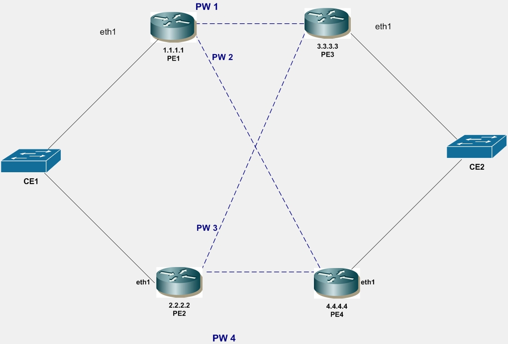
In the following topology diagram, VLAN pseudowires PW1, PW2, PW3 and PW4 are configured for VLAN-100 between PE1-PE3, PE1-PE4, PE2-PE3 and PE2-PE4 respectively. The VC-mode is configured as standby on the access interfaces of PE2 and PE4 so that PW1 is active and used for forwarding. All the other PWs will be in standby mode.
Multi-Homed CE with PW Redundancy for VLAN PW
PE1
#configure terminal | Enter Configure mode for the router. |
(config)#router ldp | Enter Router LDP mode. |
(config-router)#pw-status-tlv | Configure PW status TLV for PW status signaling. |
(config-router)#targeted-peer ipv4 3.3.3.3 | Configure targeted LDP session to PE3 loopback address. |
(config-router)#targeted-peer ipv4 4.4.4.4 | Configure targeted LDP session to PE4 loopback address. |
(config-router)#exit | Exit the Router LDP mode and return to Configure mode. |
(config)#mpls l2-circuit pw1 10 3.3.3.3 | Configure pseudowire PW1 between PE1 and PE3. |
(config-pseduowire)#exit | Exit pseudowire mode. |
(config)#mpls l2-circuit pw2 20 4.4.4.4 | Configure pseudowire PW2 between PE1 and PE4. |
(config-pseduowire)#exit | Exit pseudowire mode. |
(config)#bridge 1 protocol ieee vlan-bridge | Specify the VLAN for bridge 1. |
(config)#vlan database | Enter the VLAN Database mode. |
(config-vlan)#vlan 100 bridge 1 | Configure VLAN 100. |
(config-vlan)#exit | Exit the VLAN Database mode and return to Configure mode. |
(config)#interface eth1 | Enter interface mode. |
(config-if)#switchport | Switch to Layer-2 mode. |
(config-if)#switchport mode access | Set the switching characteristics of this interface to access mode. |
(config-if)#mpls-l2-circuit pw1 vlan 100 | Bind the pseudowire PW1 to access interface. |
(config-if)#mpls-l2-circuit pw2 vlan 100 | Bind the pseudowire PW2 to access interface. |
(config-if)#exit | Exit interface mode. |
(config)#exit | Exit the Configure mode. |
PE2
#configure terminal | Enter configure mode. |
(config)#router ldp | Enter the Router LDP mode. |
(config-router)#pw-status-tlv | Configure PW status TLV for PW status signaling. |
(config-router)#targeted-peer ipv4 3.3.3.3 | Configure targeted LDP session to PE3 loopback address. |
(config-router)#targeted-peer ipv4 4.4.4.4 | Configure targeted LDP session to PE4 loopback address. |
(config-router)#exit | Exit the Router LDP mode and return to Configure mode. |
(config)#mpls l2-circuit pw3 30 3.3.3.3 | Configure pseudowire PW3 between PE2 and PE3. |
(config-pseduowire)#exit | Exit pseudowire mode. |
(config)#mpls l2-circuit pw4 40 4.4.4.4 | Configure pseudowire PW4 between PE2 and PE4. |
(config-pseduowire)#exit | Exit pseudowire mode. |
(config)#bridge 1 protocol ieee vlan-bridge | Specify the VLAN for bridge 1. |
(config)#vlan database | Enter the VLAN Database mode. |
(config-vlan)#vlan 100 bridge 1 | Configure VLAN 100. |
(config-vlan)#exit | Exit the VLAN Database mode and return to Configure mode. |
(config)#interface eth1 | Enter interface mode. |
(config-if)#switchport | Switch to Layer-2 mode. |
(config-if)#switchport mode access | Set the switching characteristics of this Interface to Access mode. |
(config-if)#mpls-l2-circuit pw3 vlan 100 | Bind the pseudowire PW3 to access interface. |
(config-if)#mpls-l2-circuit pw4 vlan 100 | Bind the pseudowire PW4 to access interface. |
(config-if)#vc-mode standby vlan 100 | Configure VC-mode as standby for VLAN 100. Note: The command for Ethernet PWs is vc-mode standby. |
(config-if)#exit | Exit interface mode. |
(config)#exit | Exit the Configure mode. |
PE3
#configure terminal | Enter configure mode. |
(config)#router ldp | Enter the Router LDP mode. |
(config-router)#pw-status-tlv | Configure PW status TLV for PW status signaling. |
(config-router)#targeted-peer ipv4 1.1.1.1 | Configure targeted LDP session to PE1 loopback address. |
(config-router)#targeted-peer ipv4 2.2.2.2 | Configure targeted LDP session to PE2 loopback address. |
(config-router)#exit | Exit the Router LDP mode and return to Configure mode. |
(config)#mpls l2-circuit pw1 10 1.1.1.1 | Configure pseudowire PW1 between PE3 and PE1. |
(config-pseduowire)#exit | Exit pseudowire mode. |
(config)#mpls l2-circuit pw3 30 2.2.2.2 | Configure pseudowire pw2 between PE3 and PE2. |
(config-pseduowire)#exit | Exit pseudowire mode. |
(config)#bridge 1 protocol ieee vlan-bridge | Specify the VLAN for bridge 1. |
(config)#vlan database | Enter the VLAN Database mode. |
(config-vlan)#vlan 100 bridge 1 | Configure VLAN 100. |
(config-vlan)#exit | Exit the VLAN Database mode and return to Configure mode. |
(config)#interface eth1 | Enter interface mode. |
(config-if)#switchport | Switch to Layer-2 mode. |
(config-if)#switchport mode access | Set the switching characteristics of this interface to access mode. |
(config-if)#mpls-l2-circuit pw1 vlan 100 | Bind the pseudowire PW1 to access interface. |
(config-if)#mpls-l2-circuit pw3 vlan 100 | Bind the pseudowire PW3 to access interface. |
(config-if)#exit | Exit interface mode. |
(config)#exit | Exit the Configure mode. |
PE4
#configure terminal | Enter configure mode. |
(config)#router ldp | Enter the Router LDP mode. |
(config-router)#pw-status-tlv | Configure PW status TLV for PW status signaling. |
(config-router)#targeted-peer ipv4 1.1.1.1 | Configure targeted LDP session to PE1 loopback address. |
(config-router)#targeted-peer ipv4 2.2.2.2 | Configure targeted LDP session to PE2 loopback address. |
(config-router)#exit | Exit the Router LDP mode and return to Configure mode. |
(config)#mpls l2-circuit pw2 20 1.1.1.1 | Configure pseudowire PW2 between PE4 and PE3. |
(config-pseduowire)#exit | Exit pseudowire mode. |
(config)#mpls l2-circuit pw4 40 2.2.2.2 | Configure pseudowire PW4 between PE4 and PE2. |
(config-pseduowire)#exit | Exit pseudowire mode. |
(config)#bridge 1 protocol ieee vlan-bridge | Specify the VLAN for bridge 1. |
(config)#vlan database | Enter the VLAN Database mode. |
(config-vlan)#vlan 100 bridge 1 | Configure VLAN 100. |
(config-vlan)#exit | Exit the VLAN Database mode and return to Configure mode. |
(config)#interface eth1 | Enter interface mode. |
(config-if)#switchport | Switch to Layer-2 mode. |
(config-if)#switchport mode access | Set the switching characteristics of this interface to access mode. |
(config-if)#mpls-l2-circuit pw2 vlan 100 | Bind the pseudowire PW2 to access interface. |
(config-if)#mpls-l2-circuit pw4 vlan 100 | Bind the pseudowire PW4 to access interface. |
(config-if)#vc-mode standby vlan 100 | Configure VC-mode as standby for VLAN 100. Note: The command for Ethernet PWs is vc-mode standby. |
(config-if)#exit | Exit interface mode. |
(config)#exit | Exit the Configure mode. |
Remove VC-mode Standby Configuration
PE2
#configure terminal | Enter configure mode. |
(config)#interface eth1 | Enter interface mode. |
(config-if)#no vc-mode standby vlan 100 | Remove VC-mode standby for VLAN 100. |
(config-if)#exit | Exit interface mode. |
Validation
Verify the VPLS Session On DUT
PE1#show mpls vc-table
VC-ID Vlan-ID Access-Intf Network-Intf Out Label Tunnel-Label Nexthop Status
10 100 eth1 eth2 53121 3 3.3.3.3 Active
20 100 eth1 eth3 53121 3 4.4.4.4 Standby
PE1#show ldp mpls-l2-circuit detail
vcid: 10, type: ethernet, local groupid: 5, remote groupid: 5 (vc is up)
destination: 3.3.3.3, Peer LDP Ident: 3.3.3.3
Local label: 52481, remote label: 53121
Access IF: eth1, Network IF: eth2
Local MTU: 1500, Remote MTU: 1500
Local Control Word: disabled, Remote Control Word: disabled, Current use: disabled
Local PW Status Capability : enabled
Remote PW Status Capability : enabled
Current PW Status TLV : enabled
Local PW Status :
Forwarding
Active
Remote PW Status :
Forwarding
Active
vcid: 20, type: ethernet, local groupid: 5, remote groupid: 5 (vc is up)
destination: 4.4.4.4 , Peer LDP Ident: 4.4.4.4
Local label: 52480, remote label: 53121
Access IF: eth1, Network IF: eth3
Local MTU: 1500, Remote MTU: 1500
Local Control Word: disabled, Remote Control Word: disabled, Current use: disabled
Local PW Status Capability : enabled
Remote PW Status Capability : enabled
Current PW Status TLV : enabled
Local PW Status :
Not Forwarding
Remote PW Status :
Not Forwarding
Standby
MTU-s with PW Redundancy
Follow these basic configuration steps for MTU-s with PW redundancy.
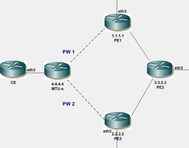
1. Configure VLAN pseudowires PW1 and PW2 between MTU-s and PE1 and MTU-s and PE2.
2. Configure PW1 as primary, PW2 as secondary and VC mode as revertive on MTU-s.
3. Configure VPLS and peer between PE1and PE3, PE2 and PE3.
4. Configure VPLS spoke VC use PW1 on PE1 and VPLS spoke VC use PW2 on PE2.
MTU-s with PW Redundancy
MTU-s
#configure terminal | Enter configure mode. |
(config)#router ldp | Enter the Router LDP mode. |
(config-router)#pw-status-tlv | Configure PW status TLV for PW status signaling. |
(config-router)#targeted-peer ipv4 1.1.1.1 | Configure targeted LDP session to PE1 loopback address. |
(config-router)#targeted-peer ipv4 2.2.2.2 | Configure targeted LDP session to PE2 loopback address. |
(config-router)#exit | Exit the Router LDP mode and return to Configure mode. |
(config)#bridge 1 protocol ieee vlan-bridge | Specify the VLAN for bridge 1. |
(config)#vlan database | Enter the VLAN database mode. |
(config-vlan)#vlan 100 bridge 1 | Configure VLAN 100. |
(config-vlan)#exit | Exit the VLAN database mode and return to Configure mode. |
(config)#mpls l2-circuit pw1 10 4.4.4.4 | Configure pseudowire PW1 between MTU-s and PE1 |
(config-pseduowire)#exit | Exit pseudowire mode. |
(config)#mpls l2-circuit pw2 20 4.4.4.4 | Configure pseudowire PW2 between MTU-s and PE2 |
(config-pseduowire)#exit | Exit pseudowire mode. |
(config)#interface eth3 | Enter interface mode. |
(config-if)#switchport | Switch to Layer-2 mode. |
(config-if)#switchport mode access | Set the switching characteristics of this interface to access mode. |
(config-if)#mpls-l2-circuit pw1 vlan 100 | Bind the PW1 as primary pseudowire to access interface |
(config-if)#mpls-l2-circuit pw2 vlan 100 secondary | Bind the PW2 as secondary pseudowire to access interface |
(config-if)#vc-mode revertive vlan 100 | Configure VC-mode as revertive. |
(config-if)#exit | Enter interface mode. |
(config)#exit | Enter configure mode. |
#vc-switchover pw1 pw2 | Configure VC-switchover to change the forwarding status of active PW1 to standby and standby PW2 to active. |
PE1
#configure terminal | Enter configure mode. |
(config)#router ldp | Enter the Router LDP mode. |
(config-router)#pw-status-tlv | Configure PW status TLV for pseudowire status signaling. |
(config-router)#targeted-peer ipv4 3.3.3.3 | Configure targeted LDP session to PE3 loopback address. |
(config-router)#targeted-peer ipv4 4.4.4.4 | Configure targeted LDP session to MTU-s loopback address. |
(config-router)#exit | Exit the Router LDP mode and return to Configure mode. |
(config)#bridge 1 protocol ieee vlan-bridge | Specify the VLAN for bridge 1. |
(config)#vlan database | Enter the VLAN Database mode. |
(config-vlan)#vlan 100 bridge 1 | Configure VLAN 100. |
(config-vlan)#exit | Exit the VLAN Database mode and return to Configure mode. |
(config)#mpls l2-circuit pw1 10 4.4.4.4 | Configure pseudowire PW1 between PE1 and MTU-s. |
(config-pseduowire)#exit | Exit pseudowire mode. |
(config)#mpls vpls v1 111 | Configure VPLS v1 with ID 111 on PE1. |
(config-vpls)#signaling ldp | Enter VPLS signaling LDP mode. |
(config-vpls-sig)#vpls-peer 3.3.3.3 | Configure PE3 as VPLS peer |
(config-vpls-sig)#exit | Exit signaling LDP mode. |
(config-vpls)#vpls-vc pw1 vlan | Configure PW1 as VLAN VC-Spoke. |
(config-vpls)#exit | Exit the VPLS mode and return to Configure mode. |
(config)#interface eth3 | Enter configure mode. |
(config-if)#switchport | Switch to Layer-2 mode. |
(config-if)#switchport mode access | Set the switching characteristics of this interface to access mode. |
(config-if)#mpls-vpls v1 | Bind the VPLS to access interface. |
(config-if)#exit | Enter interface mode. |
(config)#exit | Enter configure mode. |
PE2
#configure terminal | Enter configure mode. |
(config)#router ldp | Enter the Router LDP mode. |
(config-router)#pw-status-tlv | Configure PW status TLV for pseudowire status signaling. |
(config-router)#targeted-peer ipv4 3.3.3.3 | Configure targeted LDP session to PE3 loopback address. |
(config-router)#targeted-peer ipv4 4.4.4.4 | Configure targeted LDP session to MTU-s loopback address. |
(config-router)#exit | Exit the Router LDP mode and return to Configure mode. |
(config)#bridge 1 protocol ieee vlan-bridge | Specify the VLAN for bridge 1. |
(config)#vlan database | Enter the VLAN Database mode. |
(config-vlan)#vlan 100 bridge 1 | Configure VLAN 100. |
(config-vlan)#exit | Exit the VLAN Database mode and return to Configure mode. |
(config)#mpls l2-circuit pw2 20 4.4.4.4 | Configure pseudowire PW2 between PE2 and MTU-s. |
(config)#mpls vpls v1 111 | Configure VPLS v1 with ID 111 on PE2. |
(config-vpls)#signaling ldp | Enter VPLS signaling LDP mode. |
(config-vpls-sig)#vpls-peer 3.3.3.3 | Configure PW3 as VPLS peer. |
(config-vpls-sig)#exit | Exit signaling LDP mode. |
(config-vpls)#vpls-vc pw2 vlan | Configure PW2 as VLAN VC-spoke. |
(config-vpls)#exit | Exit the VPLS mode and return to Configure mode. |
(config)#interface eth3 | Enter interface mode. |
(config-if)#switchport | Switch to Layer-2 mode. |
(config-if)#switchport mode access | Set the switching characteristics of this interface to access mode. |
(config-if)#mpls-vpls v1 | Bind the VPLS to access interface |
(config-if)#exit | Exit interface mode. |
PE3
#configure terminal | Enter configure mode. |
(config)#router ldp | Enter the Router LDP mode. |
(config-router)#pw-status-tlv | Configure PW status TLV for PW status signaling. |
(config-router)#targeted-peer ipv4 1.1.1.1 | Configure targeted LDP session to PE1 loopback address. |
(config-router)#targeted-peer ipv4 2.2.2.2 | Configure targeted LDP session to PE2 loopback address. |
(config-router)#exit | Exit the Router LDP mode and return to Configure mode. |
(config)#mpls vpls v1 111 | Configure VPLS v1 with ID 111 on PE1. |
(config-vpls)#signaling ldp | Enter VPLS signaling LDP mode. |
(config-vpls-sig)#vpls-peer 1.1.1.1 | Configure PE1 as VPLS peer. |
(config-vpls-sig)#vpls-peer 2.2.2.2 | Configure PE2 as VPLS peer. |
(config-vpls-sig)#exit | Exit signaling LDP mode. |
(config-vpls)#exit | Exit the VPLS mode and return to Configure mode. |
(config)#interface eth3 | Enter interface mode. |
(config-if)#switchport | Switch to Layer-2 mode. |
(config-if)#switchport mode access | Set the switching characteristics of this interface to access mode. |
(config-if)#mpls-vpls v1 | Bind the VPLS to access interface. |
(config-if)#exit | Enter interface mode. |
Remove VC-mode Revertive Configuration
MTU-s
#configure terminal | Enter configure mode. |
(config)#interface eth3 | Enter interface mode. |
(config-if)#no vc-mode revertive vlan 100 | Remove VC-mode revertive for VLAN 100. |
(config-if)#exit | Enter interface mode. |
(config)#exit | Enter configure mode. |
Validation
Enter the commands listed in the section below.
Verify the VC-table Session on DUT
MTU-s#show mpls vc-table
VC-ID Vlan-ID Access-Intf Network-Intf Out Label Tunnel-Label Nexthop Status
10 100 eth3 eth1 53121 3 1.1.1.1 Active
20 100 eth3 eth2 53120 3 2.2.2.2 Standby
Verify VPLS Session on PE1
PE1#show mpls vpls detail
Virtual Private LAN Service Instance: vpls3100, ID: 3100
SIG-Protocol: BGP
Route-Distinguisher :65010:3100
Route-Target :65010:3100
VE-ID :31
Attachment-Circuit :UP
Learning: Enabled
Group ID: 0, Configured MTU: 9216
Description: none
service-tpid: dot1.q
Operating mode: Raw
Configured interfaces:
Interface: xe26
Service-template : vpls3100_3100_13100
Match criteria : 3100
Action type : Translate
Action value : 4075
Outgoing tpid : dot1.q
Mesh Peers: 3.3.3.3 (Up)
Spoke Peers: pw1 (Up)