BGP ORF Prefix-List VPNV4 Address
Overview
The Border Gateway Protocol (BGP) Outbound Route Filtering feature operates as a Prefix-Based filtering system within the BGP. Its primary purpose is to reduce the volume of BGP updates exchanged among peer routers. By selectively screening out unnecessary routing updates at the source, this feature effectively lessens the strain on resources needed for generating and handling routing updates. Its objective is to streamline router processing, especially for routers not set up to accept full BGP route updates from a service provider network.
Feature Characteristics
This feature provides customers with various routing options, such as access to routing information like a full table view, solely a default route, or a tailored subset such as a default route combined with locally originated prefixes from the service provider. Typically, BGP service providers do not impose complex outbound filtering policies on their customers.
Benefits
The advantages of Prefix-Based Outbound Route Filtering:
• Minimize unnecessary routing updates
• Reduces resources required for routing update generation and processing
• Reduces required to receive and discard routes.
Configuration
The BGP Prefix-Based Outbound Route Filtering feature offers support for prefix length matching, wildcard-based prefix matching, and exact address prefix matching across various address families. It allows configuration on a router to enable Outbound Route Filtering (ORF) capabilities for sending or receiving, using the "send" or "receive" keywords. Moreover, it permits configuration to enable both sending and receiving ORF capabilities using the "both" keyword.
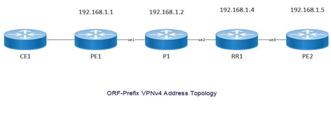
Topology
In this topology, the PE1, P1, RR1, and PE2 interface is established. It allows configuration on a router to enable Outbound Route Filtering (ORF) capabilities.
PE1
The Provider Edge (PE) 1 is a device at the edge of a service provider's network. For the PE1 configuration, follow these steps.
1. Enable activate the loopback interface, enter the following command while in configuration mode. Then, proceed to set up the IP address for the loopback interface.
PE1(config)#interface lo
PE1(config-if)#ip address 192.168.1.1/32 secondary
PE1(config-if)#enable-ldp ipv4
PE1(config)#interface lo
PE1(config-if)#ip address 192.168.1.1/32 secondary
PE1(config-if)#enable-ldp ipv4
2. To exit from the loopback interface, execute the following command.
PE1(config)#exit
PE1(config)#exit
3. Set up the Router ID. Next, configure targeted LDP sessions for PE-1. Once done, exit from targeted-peer mode. Then, configure the transport address for LDP to run on an IPv4 interface for TCP sessions.
PE1(config)#router ldp
PE1(config-router)#router-id 192.168.1.1
PE1(config-router)#targeted-peer ipv4 192.168.1.5
PE1(config-router-targeted-peer)#exit-targeted-peer-mode
PE1(config-router)#transport-address ipv4 192.168.1.1
PE1(config)#router ldp
PE1(config-router)#router-id 192.168.1.1
PE1(config-router)#targeted-peer ipv4 192.168.1.5
PE1(config-router-targeted-peer)#exit-targeted-peer-mode
PE1(config-router)#transport-address ipv4 192.168.1.1
4. To exit from the router mode for LDP, execute the following command.
PE1(config)#exit
PE1(config)#exit
5. In interface mode, assign an IP address to the interface. Then, activate label switching capability on the interface and enable LDP on it.
PE1(config)#interface xe1
PE1(config-if)#ip address 12.1.1.1/24
PE1(config-if)#label-switching
PE1(config-if)#enable-ldp ipv4
PE1(config-if)# ip ospf cost 10
PE1(config)#interface xe1
PE1(config-if)#ip address 12.1.1.1/24
PE1(config-if)#label-switching
PE1(config-if)#enable-ldp ipv4
PE1(config-if)# ip ospf cost 10
6. To exit from the interface configuration on network side, execute the following command.
PE1(config)#exit
PE1(config)#exit
7. Configure the routing process and specify the Process ID, (100). The Process ID should be a unique positive integer to identifying the routing process.
PE1(config)# router ospf 100
PE1(config)# router ospf 100
8. Configure the OSPF Router ID and define the interface for OSPF operation and link it with the area ID (0).
PE1(config-router)# ospf router-id 192.168.1.1
PE1(config-router)# bfd all-interfaces
PE1(config-router)# timers spf exp 50 50
PE1(config-router)# timers throttle lsa all 0 1 1
PE1(config-router)# network 12.1.1.0/24 area 0.0.0.0
PE1(config-router)# network 192.168.1.1/32 area 0.0.0.0
PE1(config-router)# ospf router-id 192.168.1.1
PE1(config-router)# bfd all-interfaces
PE1(config-router)# timers spf exp 50 50
PE1(config-router)# timers throttle lsa all 0 1 1
PE1(config-router)# network 12.1.1.0/24 area 0.0.0.0
PE1(config-router)# network 192.168.1.1/32 area 0.0.0.0
9. To exit from the OSPF, execute the following command.
PE1(config)#exit
PE1(config)#exit
10. Switch to BGP router mode. Establish PE1 as an iBGP peer. Specify the loopback as the source for iBGP peering with the remote PE1 router. Activate PE1 in the VPNv4 unicast address family.
PE1(config)#router bgp 100
PE1(config-router)# bgp router-id 192.168.1.1
PE1(config-router)# neighbor 192.168.1.4 remote-as 100
PE1(config-router)# neighbor 192.168.1.4 update-source lo
PE1(config-router)# neighbor 192.168.1.4 advertisement-interval 0
PE1(config-router)# address-family vpnv4 unicast
PE1(config-router-af)# neighbor 192.168.1.4 activate
PE1(config-router-af)# neighbor 192.168.1.4 capability orf prefix-list receive
PE1(config-router-af)# exit-address-family
11. To exit from the BGP, execute the following command.
PE1(config)#exit
PE1(config)#exit
P
The Provider (P) is a device at the edge of a service provider's network. For the P configuration, follow these steps.
1. Enable activate the loopback interface, enter the following command while in configuration mode. Then, proceed to set up the IP address for the loopback interface.
P(config)#interface lo
P(config-if)#ip address 192.168.1.1/32 secondary
P(config-if)#enable-ldp ipv4
P(config)#interface lo
P(config-if)#ip address 192.168.1.1/32 secondary
P(config-if)#enable-ldp ipv4
2. To exit from the loopback interface, execute the following command.
P(config)#exit
P(config)#exit
3. Set up the Router ID. Next, configure targeted LDP sessions for P. Once done, exit from targeted-peer mode. Then, configure the transport address for LDP to run on an IPv4 interface for TCP sessions.
P(config)#router ldp
P(config-router)#router-id 192.168.1.2
P(config-router)#targeted-peer ipv4 192.168.1.2
P(config)#router ldp
P(config-router)#router-id 192.168.1.2
P(config-router)#targeted-peer ipv4 192.168.1.2
4. To exit from the router mode for LDP, execute the following command.
P(config)#exit
P(config)#exit
5. In interface mode, assign an IP address to the interface. Then, activate label switching capability on the interface and enable LDP on it.
P(config)#interface xe1
P(config-if)#ip address 12.1.1.1/24
P(config-if)#label-switching
P(config)#interface xe1
P(config-if)#ip address 13.1.1.2/24
P(config-if)#label-switching
P(config)#interface xe1
P(config-if)#ip address 12.1.1.1/24
P(config-if)#label-switching
P(config)#interface xe1
P(config-if)#ip address 13.1.1.2/24
P(config-if)#label-switching
6. To exit from the interface configuration on network side, execute the following command.
P(config)#exit
P(config)#exit
7. Configure the routing process and specify the Process ID, (100). The Process ID should be a unique positive integer to identifying the routing process.
P(config)# router ospf 100
P(config)# router ospf 100
8. Configure the OSPF Router ID and define the interface for OSPF operation and link it with the area ID (0).
P(config-router)# ospf router-id 192.168.1.2
P(config-router)# bfd all-interfaces
P(config-router)# timers spf exp 50 50
P(config-router)# timers throttle lsa all 0 1 1
P(config-router)# network 12.1.1.0/24 area 0.0.0.0
P(config-router)# network 192.168.1.1/32 area 0.0.0.0
P(config-router)# ospf router-id 192.168.1.2
P(config-router)# bfd all-interfaces
P(config-router)# timers spf exp 50 50
P(config-router)# timers throttle lsa all 0 1 1
P(config-router)# network 12.1.1.0/24 area 0.0.0.0
P(config-router)# network 192.168.1.1/32 area 0.0.0.0
9. To exit from the OSPF, execute the following command.
P(config)#exit
P(config)#exit
RR
Route Reflector (RR) is a designated router that will reflect routes learned from other iBGP peers. All routers form a peering relationship only with the Route Reflector. For the RR configuration, follow these steps.
1. Enable activate the loopback interface, enter the following command while in configuration mode. Then, proceed to set up the IP address for the loopback interface.
RR(config)#interface lo
RR(config-if)#ip address 192.168.1.1/32 secondary
RR(config-if)#enable-ldp ipv4
RR(config)#interface lo
RR(config-if)#ip address 192.168.1.1/32 secondary
RR(config-if)#enable-ldp ipv4
2. To exit from the loopback interface, execute the following command.
RR(config)#exit
RR(config)#exit
3. Set up the Router ID. Next, configure targeted LDP sessions for P. Once done, exit from targeted-peer mode. Then, configure the transport address for LDP to run on an IPv4 interface for TCP sessions.
RR(config)#router ldp
RR(config-router)#router-id 192.168.1.4/32
RR(config-router)#transport-address ipv4 192.168.1.4
RR(config)#router ldp
RR(config-router)#router-id 192.168.1.4/32
RR(config-router)#transport-address ipv4 192.168.1.4
4. To exit from the router mode for LDP, execute the following command.
RR(config)#exit
RR(config)#exit
5. In interface mode, set up the IP address for the interface and activate label switching capability on it.
RR(config)#interface xe1
RR(config-if)#ip address 12.1.1.1/24
RR(config-if)#label-switching
RR(config-if)#enable-ldp ipv4
RR(config)#interface xe3
RR(config-if)#ip address 14.1.1.1/24
RR(config-if)#label-switching
RR(config-if)#enable-ldp ipv4
RR(config)#interface xe1
RR(config-if)#ip address 12.1.1.1/24
RR(config-if)#label-switching
RR(config-if)#enable-ldp ipv4
RR(config)#interface xe3
RR(config-if)#ip address 14.1.1.1/24
RR(config-if)#label-switching
RR(config-if)#enable-ldp ipv4
6. To exit from the interface configuration on network side, execute the following command.
RR(config)#exit
RR(config)#exit
7. Configure the routing process and specify the Process ID, (100). The Process ID should be a unique positive integer to identifying the routing process.
RR(config)# router ospf 100
RR(config)# router ospf 100
8. Configure the OSPF Router ID and define the interface for OSPF operation and link it with the area ID (0).
RR(config-router)# ospf router-id 192.168.1.4
RR(config-router)# bfd all-interfaces
RR(config-router)# timers spf exp 50 50
RR(config-router)# timers throttle lsa all 0 1 1
RR(config-router)# network 12.1.1.0/24 area 0.0.0.0
RR(config-router)# network 192.168.1.1/32 area 0.0.0.0
RR(config-router)# ospf router-id 192.168.1.4
RR(config-router)# bfd all-interfaces
RR(config-router)# timers spf exp 50 50
RR(config-router)# timers throttle lsa all 0 1 1
RR(config-router)# network 12.1.1.0/24 area 0.0.0.0
RR(config-router)# network 192.168.1.1/32 area 0.0.0.0
9. To exit from the OSPF, execute the following command.
RR(config)#exit
RR(config)#exit
10. Switch to BGP router mode. Establish RR as an iBGP peer. Specify the loopback as the source for iBGP peering with the remote RR router. Activate RR in the VPNv4 unicast address family.
RR(config)#router bgp 100
RR(config-router)# bgp router-id 192.168.1.1
RR(config-router)# neighbor 192.168.1.4 remote-as 100
RR(config-router)# neighbor 192.168.1.4 update-source lo
RR(config-router)# neighbor 192.168.1.4 advertisement-interval 0
RR(config-router)# address-family vpnv4 unicast
RR(config-router-af)# neighbor 192.168.1.4 active
RR(config-router-af)# neighbor 192.168.1.4 capability orf prefix-list s
RR(config-router-af)# neighbor 192.168.1.1 prefix-list
RR(config-router-af)# exit-address-family
11. To exit from the BGP, execute the following command.
PE1(config)#exit
PE1(config)#exit
12. To configure the global prefix, execute the following command in the global mode.
RR(config)# ip prefix-list ORF1
RR(config-ip-prefix-list)# seq 1 permit 45.1.1.0/24
RR(config)# ip prefix-list ORF1
RR(config-ip-prefix-list)# seq 1 permit 45.1.1.0/24
13. To exit from the BGP, execute the following command.
RR(config)#exit
RR(config)#exit
PE2
The Provider Edge (PE) 2 is a device at the edge of a service provider's network. For the PE2 configuration, follow these steps.
1. Enable activate the loopback interface, enter the following command while in configuration mode. Then, proceed to set up the IP address for the loopback interface.
PE2(config)#interface lo
PE2(config-if)#ip address 192.168.1.1/32 secondary
PE2(config-if)#enable-ldp ipv4
PE2(config)#interface lo
PE2(config-if)#ip address 192.168.1.1/32 secondary
PE2(config-if)#enable-ldp ipv4
2. To exit from the loopback interface, execute the following command.
PE2(config)#exit
PE2(config)#exit
3. Set up the Router ID. Next, configure targeted LDP sessions for P. Once done, exit from targeted-peer mode. Then, configure the transport address for LDP to run on an IPv4 interface for TCP sessions.
PE2(config)#router ldp
PE2(config-router)#router-id 192.168.1.1
PE2(config-router)#targeted-peer ipv4 192.168.1.5
PE2(config-router-targeted-peer)#exit-targeted-peer-mode
PE2(config-router)#transport-address ipv4 192.168.1.1
PE2(config-router)#transport-address ipv4 192.168.1.5
PE2(config)#router ldp
PE2(config-router)#router-id 192.168.1.1
PE2(config-router)#targeted-peer ipv4 192.168.1.5
PE2(config-router-targeted-peer)#exit-targeted-peer-mode
PE2(config-router)#transport-address ipv4 192.168.1.1
PE2(config-router)#transport-address ipv4 192.168.1.5
4. To exit from the router mode for LDP, execute the following command.
PE2(config)#exit
PE2(config)#exit
5. In interface mode, assign an IP address to the interface. Then, activate label switching capability on the interface and enable LDP on it.
PE2(config)#interface xe1
PE2(config-if)#ip address 12.1.1.1/24
PE2(config-if)#label-switching
PE2(config-if)#enable-ldp ipv4
PE2(config-if)# ip ospf cost 10
PE2(config)#interface xe1
PE2(config-if)#ip address 12.1.1.1/24
PE2(config-if)#label-switching
PE2(config-if)#enable-ldp ipv4
PE2(config-if)# ip ospf cost 10
6. To exit from the interface configuration on network side, execute the following command.
PE2(config)#exit
PE2(config)#exit
7. Configure the routing process and specify the Process ID, (100). The Process ID should be a unique positive integer to identifying the routing process.
PE2(config)# router ospf 100
PE2(config)# router ospf 100
8. Configure the OSPF Router ID and define the interface for OSPF operation and link it with the area ID (0).
PE2(config-router)# ospf router-id 192.168.1.1
PE2(config-router)# bfd all-interfaces
PE2(config-router)# timers spf exp 50 50
PE2(config-router)# timers throttle lsa all 0 1 1
PE2(config-router)# network 12.1.1.0/24 area 0.0.0.0
PE2(config-router)# network 192.168.1.1/32 area 0.0.0.0
PE2(config-router)# ospf router-id 192.168.1.1
PE2(config-router)# bfd all-interfaces
PE2(config-router)# timers spf exp 50 50
PE2(config-router)# timers throttle lsa all 0 1 1
PE2(config-router)# network 12.1.1.0/24 area 0.0.0.0
PE2(config-router)# network 192.168.1.1/32 area 0.0.0.0
9. To exit from the OSPF, execute the following command.
PE2(config)#exit
PE2(config)#exit
10. Switch to BGP router mode. Establish PE2 as an iBGP peer. Specify the loopback as the source for iBGP peering with the remote PE2 router. Activate PE2 in the VPNv4 unicast address family.
PE2(config)#router bgp 100
PE2(config-router)# bgp router-id 192.168.1.1
PE2(config-router)# neighbor 192.168.1.4 remote-as 100
PE2(config-router)# neighbor 192.168.1.4 update-source lo
PE2(config-router)# neighbor 192.168.1.4 advertisement-interval 0
PE2(config-router)# address-family vpnv4 unicast
PE2(config-router-af)# neighbor 192.168.1.4 activate
PE2(config-router-af)# exit-address-family
11. To exit from the BGP, execute the following command.
PE2(config)#exit
PE2(config)#exit
Validation
PE1-7017#show ip bgp vpnv4 all
Status codes: s suppressed, d damped, h history, a add-path, b back-up, * valid,
> best, i - internal, l - labeled
S Stale
Origin codes: i - IGP, e - EGP, ? - incomplete
Network Next Hop Metric LocPrf Weight Path
Route Distinguisher: 192.168.1.1:100 (Default for VRF vrf100)
*> l 45.1.1.0/24 100.1.1.2 0 100 0 400 i
*> l 45.1.2.0/24 100.1.1.2 0 100 0 400 i
*> l 45.1.3.0/24 100.1.1.2 0 100 0 400 i
*> l 45.1.4.0/24 100.1.1.2 0 100 0 400 i
*> l 45.1.5.0/24 100.1.1.2 0 100 0 400 i
*> l 45.1.6.0/24 100.1.1.2 0 100 0 400 i
*> l 45.1.7.0/24 100.1.1.2 0 100 0 400 i
*> l 45.1.8.0/24 100.1.1.2 0 100 0 400 i
*> l 45.1.9.0/24 100.1.1.2 0 100 0 400 i
*> l 45.1.10.0/24 100.1.1.2 0 100 0 400 i
*> l 100.1.1.0/24 0.0.0.0 0 100 32768 ?
*> 100.1.2.0/24 0.0.0.0 0 100 32768 ?
*> 100.1.3.0/24 0.0.0.0 0 100 32768 ?
*> 100.1.4.0/24 0.0.0.0 0 100 32768 ?
*> 100.1.5.0/24 0.0.0.0 0 100 32768 ?
*>il 200.1.1.0 192.168.1.4 0 100 0 ?
*>il 200.1.2.0 192.168.1.4 0 100 0 ?
*>il 200.1.3.0 192.168.1.4 0 100 0 ?
*>il 200.1.4.0 192.168.1.4 0 100 0 ?
*>il 200.1.5.0 192.168.1.4 0 100 0 ?
Announced routes count = 15
Accepted routes count = 5
Route Distinguisher: 192.168.1.1:101 (Default for VRF vrf101)
*> 45.1.1.0/24 100.1.1.2 0 100 0 400 i
*> 45.1.2.0/24 100.1.1.2 0 100 0 400 i
*> 45.1.3.0/24 100.1.1.2 0 100 0 400 i
*> 45.1.4.0/24 100.1.1.2 0 100 0 400 i
*> 45.1.5.0/24 100.1.1.2 0 100 0 400 i
*> 45.1.6.0/24 100.1.1.2 0 100 0 400 i
*> 45.1.7.0/24 100.1.1.2 0 100 0 400 i
*> 45.1.8.0/24 100.1.1.2 0 100 0 400 i
*> 45.1.9.0/24 100.1.1.2 0 100 0 400 i
*> 45.1.10.0/24 100.1.1.2 0 100 0 400 i
*> 100.1.1.0/24 0.0.0.0 0 100 32768 ?
*> l 100.1.2.0/24 0.0.0.0 0 100 32768 ?
*> 100.1.3.0/24 0.0.0.0 0 100 32768 ?
*> 100.1.4.0/24 0.0.0.0 0 100 32768 ?
*> 100.1.5.0/24 0.0.0.0 0 100 32768 ?
*>il 200.1.1.0 192.168.1.4 0 100 0 ?
*>il 200.1.2.0 192.168.1.4 0 100 0 ?
*>il 200.1.3.0 192.168.1.4 0 100 0 ?
*>il 200.1.4.0 192.168.1.4 0 100 0 ?
*>il 200.1.5.0 192.168.1.4 0 100 0 ?
Announced routes count = 15
Accepted routes count = 5
Route Distinguisher: 192.168.1.1:102 (Default for VRF vrf102)
*> 45.1.1.0/24 100.1.1.2 0 100 0 400 i
*> 45.1.2.0/24 100.1.1.2 0 100 0 400 i
*> 45.1.3.0/24 100.1.1.2 0 100 0 400 i
*> 45.1.4.0/24 100.1.1.2 0 100 0 400 i
*> 45.1.5.0/24 100.1.1.2 0 100 0 400 i
*> 45.1.6.0/24 100.1.1.2 0 100 0 400 i
*> 45.1.7.0/24 100.1.1.2 0 100 0 400 i
*> 45.1.8.0/24 100.1.1.2 0 100 0 400 i
*> 45.1.9.0/24 100.1.1.2 0 100 0 400 i
*> 45.1.10.0/24 100.1.1.2 0 100 0 400 i
*> 100.1.1.0/24 0.0.0.0 0 100 32768 ?
*> 100.1.2.0/24 0.0.0.0 0 100 32768 ?
*> l 100.1.3.0/24 0.0.0.0 0 100 32768 ?
*> 100.1.4.0/24 0.0.0.0 0 100 32768 ?
*> 100.1.5.0/24 0.0.0.0 0 100 32768 ?
*>il 200.1.1.0 192.168.1.4 0 100 0 ?
*>il 200.1.2.0 192.168.1.4 0 100 0 ?
*>il 200.1.3.0 192.168.1.4 0 100 0 ?
*>il 200.1.4.0 192.168.1.4 0 100 0 ?
*>il 200.1.5.0 192.168.1.4 0 100 0 ?
Announced routes count = 15
Accepted routes count = 5
Route Distinguisher: 192.168.1.1:103 (Default for VRF vrf103)
*> 45.1.1.0/24 100.1.1.2 0 100 0 400 i
*> 45.1.2.0/24 100.1.1.2 0 100 0 400 i
*> 45.1.3.0/24 100.1.1.2 0 100 0 400 i
*> 45.1.4.0/24 100.1.1.2 0 100 0 400 i
*> 45.1.5.0/24 100.1.1.2 0 100 0 400 i
*> 45.1.6.0/24 100.1.1.2 0 100 0 400 i
*> 45.1.7.0/24 100.1.1.2 0 100 0 400 i
*> 45.1.8.0/24 100.1.1.2 0 100 0 400 i
*> 45.1.9.0/24 100.1.1.2 0 100 0 400 i
*> 45.1.10.0/24 100.1.1.2 0 100 0 400 i
*> 100.1.1.0/24 0.0.0.0 0 100 32768 ?
*> 100.1.2.0/24 0.0.0.0 0 100 32768 ?
*> 100.1.3.0/24 0.0.0.0 0 100 32768 ?
*> l 100.1.4.0/24 0.0.0.0 0 100 32768 ?
*> 100.1.5.0/24 0.0.0.0 0 100 32768 ?
*>il 200.1.1.0 192.168.1.4 0 100 0 ?
*>il 200.1.2.0 192.168.1.4 0 100 0 ?
*>il 200.1.3.0 192.168.1.4 0 100 0 ?
*>il 200.1.4.0 192.168.1.4 0 100 0 ?
*>il 200.1.5.0 192.168.1.4 0 100 0 ?
Announced routes count = 15
Accepted routes count = 5
Route Distinguisher: 192.168.1.1:104 (Default for VRF vrf104)
*> 45.1.1.0/24 100.1.1.2 0 100 0 400 i
*> 45.1.2.0/24 100.1.1.2 0 100 0 400 i
*> 45.1.3.0/24 100.1.1.2 0 100 0 400 i
*> 45.1.4.0/24 100.1.1.2 0 100 0 400 i
*> 45.1.5.0/24 100.1.1.2 0 100 0 400 i
*> 45.1.6.0/24 100.1.1.2 0 100 0 400 i
*> 45.1.7.0/24 100.1.1.2 0 100 0 400 i
*> 45.1.8.0/24 100.1.1.2 0 100 0 400 i
*> 45.1.9.0/24 100.1.1.2 0 100 0 400 i
*> 45.1.10.0/24 100.1.1.2 0 100 0 400 i
*> 100.1.1.0/24 0.0.0.0 0 100 32768 ?
*> 100.1.2.0/24 0.0.0.0 0 100 32768 ?
*> 100.1.3.0/24 0.0.0.0 0 100 32768 ?
*> 100.1.4.0/24 0.0.0.0 0 100 32768 ?
*> l 100.1.5.0/24 0.0.0.0 0 100 32768 ?
*>il 200.1.1.0 192.168.1.4 0 100 0 ?
*>il 200.1.2.0 192.168.1.4 0 100 0 ?
*>il 200.1.3.0 192.168.1.4 0 100 0 ?
*>il 200.1.4.0 192.168.1.4 0 100 0 ?
*>il 200.1.5.0 192.168.1.4 0 100 0 ?
Announced routes count = 15
Accepted routes count = 5
Route Distinguisher: 192.168.1.6:100
*>il 200.1.1.0 192.168.1.4 0 100 0 ?
* il 192.168.1.5 0 100 0 ?
Announced routes count = 0
Accepted routes count = 2
Route Distinguisher: 192.168.1.6:101
*>il 200.1.2.0 192.168.1.4 0 100 0 ?
* il 192.168.1.5 0 100 0 ?
Announced routes count = 0
Accepted routes count = 2
Route Distinguisher: 192.168.1.6:102
*>il 200.1.3.0 192.168.1.4 0 100 0 ?
* il 192.168.1.5 0 100 0 ?
Announced routes count = 0
Accepted routes count = 2
Route Distinguisher: 192.168.1.6:103
*>il 200.1.4.0 192.168.1.4 0 100 0 ?
* il 192.168.1.5 0 100 0 ?
Announced routes count = 0
Accepted routes count = 2
Route Distinguisher: 192.168.1.6:104
*>il 200.1.5.0 192.168.1.4 0 100 0 ?
* il 192.168.1.5 0 100 0 ?
Announced routes count = 0
Accepted routes count = 2x
Use these commands to validate the BGP Neighbor Table.
PE1#show ip bgp neighbors 192.168.1.4
BGP neighbor is 192.168.1.4, remote AS 100, local AS 100, internal link, peer in
dex: 32
BGP version 4, local router ID 192.168.1.1, remote router ID 192.168.1.4
BGP state = Established, up for 00:05:03
Last read 00:00:18, hold time is 90, keepalive interval is 30 seconds
Neighbor capabilities:
Route refresh: advertised and received (old and new)
Address family IPv4 Unicast: advertised and received
Address family IPv4 Labeled-Unicast: advertised and received
Address family VPNv4 Unicast: advertised and received
Address family L2VPN VPLS: advertised and received
Address family L2VPN EVPN: advertised and received
Address family IPv6 Unicast: advertised and received
Address family VPNv6 Unicast: advertised and received
Address family IPv6 Labeled Unicast: advertised and received
Received 3229 messages, 1 notifications, 0 in queue
Sent 3252 messages, 2 notifications, 0 in queue
Route refresh request: received 2, sent 0
Minimum time between advertisement runs is 0 seconds
Update source is lo
For address family: IPv4 Unicast BGP table version 4, neighbor version 4
Index 1, Offset 0, Mask 0x2
AIGP is enabled
Community attribute sent to this neighbor (both)
Large Community attribute sent to this neighbor
4 accepted prefixes
1 announced prefixes
For address family: VPNv4 Unicast BGP table version 2, neighbor version 2
Index 1, Offset 0, Mask 0x2
AIGP is enabled
AF-dependant capabilities:
Outbound Route Filter (ORF) type (64) Prefix-list:
Send-mode: received
Receive-mode: advertised
Outbound Route Filter (ORF) type (128) Prefix-list:
Send-mode: received
Receive-mode: advertised
Outbound Route Filter (ORF): received (1 entries)
Community attribute sent to this neighbor (both)
Large Community attribute sent to this neighbor
5 accepted prefixes
1 announced prefixes
For address family: IPv4 Labeled-Unicast BGP table version 6, neighbor version
5
Index 1, Offset 0, Mask 0x2
AIGP is enabled
Community attribute sent to this neighbor (both)
Large Community attribute sent to this neighbor
4 accepted prefixes
1 announced prefixes
For address family: L2VPN VPLS BGP table version 1, neighbor version 1
Index 1, Offset 0, Mask 0x2
Community attribute sent to this neighbor (both)
Large Community attribute sent to this neighbor
0 accepted prefixes
9 announced prefixes
For address family: L2VPN EVPN BGP table version 3, neighbor version 3
Index 1, Offset 0, Mask 0x2
Community attribute sent to this neighbor (both)
Large Community attribute sent to this neighbor
20 accepted prefixes
Accepted AD:10 MACIP:0 MCAST:10 ESI:0 PREFIX:0
20 announced prefixes
For address family: IPv6 Unicast BGP table version 2, neighbor version 1
Index 1, Offset 0, Mask 0x2
AIGP is enabled
Community attribute sent to this neighbor (both)
Large Community attribute sent to this neighbor
0 accepted prefixes
0 announced prefixes
For address family: VPNv6 Unicast BGP table version 2, neighbor version 1
Index 1, Offset 0, Mask 0x2
Community attribute sent to this neighbor (both)
Large Community attribute sent to this neighbor
4 accepted prefixes
5 announced prefixes
For address family: 6PE Labeled Unicast BGP table version 1, neighbor version 1
Index 1, Offset 0, Mask 0x2
Community attribute sent to this neighbor (both)
Large Community attribute sent to this neighbor
10 accepted prefixes
10 announced prefixes
Connections established 4; dropped 3
Local host: 192.168.1.1, Local port: 179
Foreign host: 192.168.1.4, Foreign port: 44897
TCP MSS: (0), Advertise TCP MSS: (9176), Send TCP MSS: (1460), Receive TCP MSS:
(1460)
Sock FD : (43)
Nexthop: 192.168.1.1
Nexthop global: ::
Nexthop local: ::
BGP connection: non shared network
Last Reset: 00:05:03, due to Administratively Reset (Cease Notification sent)
Notification Error Message: (Cease/Administratively Reset.)
Use these commands to validate the RR configuration.
# RR1-7038#SH IP BGP VPNV4 ALL
Status codes: s suppressed, d damped, h history, a add-path, b back-up, * valid,
> best, i - internal, l - labeled
S Stale
Origin codes: i - IGP, e - EGP, ? - incomplete
Network Next Hop Metric LocPrf Weight Path
Route Distinguisher: 192.168.1.1:100
*>il 45.1.1.0/24 192.168.1.1 0 100 0 400 i
Announced routes count = 0
Accepted routes count = 1
Route Distinguisher: 192.168.1.6:100
*>il 200.1.1.0 192.168.1.6 0 100 0 ?
Announced routes count = 0
Accepted routes count = 1
Route Distinguisher: 192.168.1.6:101
*>il 200.1.2.0 192.168.1.6 0 100 0 ?
Announced routes count = 0
Accepted routes count = 1
Route Distinguisher: 192.168.1.6:102
*>il 200.1.3.0 192.168.1.6 0 100 0 ?
Announced routes count = 0
Accepted routes count = 1
Route Distinguisher: 192.168.1.6:103
*>il 200.1.4.0 192.168.1.6 0 100 0 ?
Announced routes count = 0
Accepted routes count = 1
Route Distinguisher: 192.168.1.6:104
*>il 200.1.5.0 192.168.1.6 0 100 0 ?
Announced routes count = 0
Accepted routes count = 1
RR1-7038#show ip bgp neighbors 192.168.1.1
BGP neighbor is 192.168.1.1, remote AS 100, local AS 100, internal link, peer in
dex: 2
BGP version 4, local router ID 192.168.1.4, remote router ID 192.168.1.1
BGP state = Established, up for 00:06:19
Last read 00:00:09, hold time is 90, keepalive interval is 30 seconds
Neighbor capabilities:
Route refresh: advertised and received (old and new)
Address family IPv4 Unicast: advertised and received
Address family IPv4 Labeled-Unicast: advertised and received
Address family VPNv4 Unicast: advertised and received
Address family L2VPN VPLS: advertised and received
Address family L2VPN EVPN: advertised and received
Address family IPv6 Unicast: advertised and received
Address family VPNv6 Unicast: advertised and received
Address family IPv6 Labeled Unicast: advertised and received
Received 3244 messages, 2 notifications, 0 in queue
Sent 3242 messages, 2 notifications, 0 in queue
Route refresh request: received 0, sent 2
Minimum time between advertisement runs is 0 seconds
Update source is lo
For address family: IPv4 Unicast BGP table version 3, neighbor version 3
Index 1, Offset 0, Mask 0x2
AIGP is enabled
Route-Reflector Client
Community attribute sent to this neighbor (both)
Large Community attribute sent to this neighbor
1 accepted prefixes
4 announced prefixes
For address family: VPNv4 Unicast BGP table version 3, neighbor version 3
Index 1, Offset 0, Mask 0x2
AIGP is enabled
AF-dependant capabilities:
Outbound Route Filter (ORF) type (64) Prefix-list:
Send-mode: advertised
Receive-mode: received
Outbound Route Filter (ORF) type (128) Prefix-list:
Send-mode: advertised
Receive-mode: received
Outbound Route Filter (ORF): sent;
Route-Reflector Client
NEXT_HOP is always this router
Community attribute sent to this neighbor (both)
Large Community attribute sent to this neighbor
Inbound path policy configured
Incoming update prefix filter list is *ORF1
1 accepted prefixes
5 announced prefixes
For address family: IPv4 Labeled-Unicast BGP table version 6, neighbor version
6
Index 1, Offset 0, Mask 0x2
AIGP is enabled
Route-Reflector Client
NEXT_HOP is always this router
Community attribute sent to this neighbor (both)
Large Community attribute sent to this neighbor
1 accepted prefixes
4 announced prefixes
For address family: L2VPN VPLS BGP table version 1, neighbor version 1
Index 1, Offset 0, Mask 0x2
Route-Reflector Client
Community attribute sent to this neighbor (both)
Large Community attribute sent to this neighbor
0 accepted prefixes
9 announced prefixes
For address family: L2VPN EVPN BGP table version 5, neighbor version 5
Index 1, Offset 0, Mask 0x2
Route-Reflector Client
Community attribute sent to this neighbor (both)
Large Community attribute sent to this neighbor
20 accepted prefixes
Accepted AD:10 MACIP:0 MCAST:10 ESI:0 PREFIX:0
20 announced prefixes
For address family: IPv6 Unicast BGP table version 1, neighbor version 1
Index 1, Offset 0, Mask 0x2
AIGP is enabled
Route-Reflector Client
Community attribute sent to this neighbor (both)
Large Community attribute sent to this neighbor
0 accepted prefixes
0 announced prefixes
For address family: VPNv6 Unicast BGP table version 3, neighbor version 3
Index 1, Offset 0, Mask 0x2
Route-Reflector Client
Community attribute sent to this neighbor (both)
Large Community attribute sent to this neighbor
5 accepted prefixes
5 announced prefixes
For address family: 6PE Labeled Unicast BGP table version 3, neighbor version 3
Index 1, Offset 0, Mask 0x2
Route-Reflector Client
Community attribute sent to this neighbor (both)
Large Community attribute sent to this neighbor
10 accepted prefixes
10 announced prefixes
Connections established 4; dropped 3
Local host: 192.168.1.4, Local port: 44897
Foreign host: 192.168.1.1, Foreign port: 179
TCP MSS: (0), Advertise TCP MSS: (1460), Send TCP MSS: (1460), Receive TCP MSS:
(1460)
Sock FD : (26)
Nexthop: 192.168.1.4
Nexthop global: ::
Nexthop local: ::
BGP connection: non shared network
Last Reset: 00:06:19, due to BGP Notification received
Notification Error Message: (Cease/Administratively Reset.)
RR1-7038#
Glossary
The following provides definitions for key terms or abbreviations and their meanings used throughout this document:
Key Terms/Acronym | Description |
|---|---|
ORF | ORF stands for Outbound Route Filtering. It is a feature in routing protocols, particularly in BGP (Border Gateway Protocol), that allows a router to advertise to its neighbor routers the set of routes it can accept or reject. |
LDP | LDP stands for Label Distribution Protocol. It is a signaling protocol used in MPLS (Multiprotocol Label Switching) networks to distribute and exchange labels between MPLS-enabled routers. |
OSPF | OSPF stands for Open Shortest Path First. It is a routing protocol used in computer networks, particularly in large enterprise and service provider networks. |