Y.1731 and CFM Over VPLS Sub-Interface
Overview
Y.1731 Connectivity Fault Management (CFM) over Layer 2 Virtual Private LAN Service (VPLS) is a protocol and technology combination used for fault management in Layer 2 VPN networks. It allows for the detection and management of faults, performance monitoring, and fault localization within a VPLS network
Feature Characteristics
• Facilitates end-to-end fault management across the VPLS network, covering provider and customer edges.
• Supports multi-level fault management, allowing operators to define different levels of fault detection and management for different parts of the network.
• Y.1731 CFM includes performance monitoring capabilities, such as delay measurement and frame loss measurement, to monitor service quality parameters.
• The protocol supports loopback and link trace functions to identify and troubleshoot faults within the VPLS network.
Benefits
• Enables rapid detection and localization of faults within the VPLS network, minimizing downtime and service disruptions.
• Provides performance monitoring capabilities, allowing to track key performance indicators and ensure service quality.
• Enhances network visibility by providing detailed fault and performance monitoring data, aiding in network troubleshooting and maintenance.
Prerequisites
Ensure the network devices participating in the L2VPN VPLS setup support Y.1731 CFM functionality. This includes the Provider Edge (PE) and Customer Edge (CE) devices.
Configuration
Configure Y.1731 CFM over sub-interface using L2VPN VPLS by defining the CFM domain, configuring service MEPs and MAs, and setting up cross-connects between primary and backup interfaces.
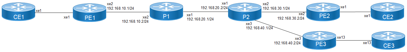
Topology
The topology consists of three Customer Edge devices (CE1, CE2, and CE3) connected to three Provider Edge devices (PE1, PE2, and PE3) via sub-interfaces (xe1, xe12, and xe13). The Provider Edge devices are interconnected through Provider Devices (P1 and P2). Y.1731 ethernet CFM is configured over these sub-interfaces to monitor and manage ethernet connectivity between the CE devices, ensuring fault detection and performance monitoring across the service provider's network.
L2VPN VPLS Y1731 CFM Over Sub-interface
Perform the following configurations to configure Y.1731 CFM over sub-interface using L2VPN VPLS:
1. On Customer Edge (CE) Nodes (CE1, CE2, and CE3), configure the interface xe1 and set it as a switchport with a load interval of (30 seconds):
CE1(config)#interface xe1
CE1(config-if)#switchport
CE1(config-if)#load-interval 30
CE1(config-if)#commit
CE1(config-if)#exit
Note: Similarly follow the same steps to configure xe11(CE1), xe12(CE2), and xe13(CE3).
2. Create sub-interface (xe1.2001)adding the VLAN:
CE1(config)#interface xe1.2001 switchport
CE1(config-if)#encapsulation dot1q 2028
CE1(config-if)#commit
CE1(config-if)#exit
CE1(config)#interface xe11.2001 switchport
CE1(config-if)#encapsulation dot1q 2028
CE1(config-if)#commit
CE1(config-if)#exit
3. Set up a cross-connect named (test100), specifying in and out interfaces:
CE1(config)#cross-connect test100
CE1(config-xc)#interface xe1.2001
CE1(config-xc)#interface xe11.2001
CE1(config-xc)#commit
4. Perform the following on PE1:
1. Configure CFM related hardware profiles:
PE1(config)# hardware-profile filter cfm-domain-name-str enable
PE1(config)# hardware-profile statistics cfm-lm enable
PE1(config)# hardware-profile statistics cfm-ccm enable
PE1(config)#hardware-profile statistics cfm-slm enable
2. Configure the loopback interface with a secondary IP address(1.1.1.1/32):
PE1(config)#interface lo
PE1(config-if)#ip address 1.1.1.1/32 secondary
PE1(config-if)#commit
PE1(config-if)#exit
3. Configure LDP targeted peers:
PE1(config)#router ldp
PE1(config-router)#targeted-peer ipv4 4.4.4.4
PE1(config-router-targeted-peer)#exit-targeted-peer-mode
PE1(config-router)#targeted-peer ipv4 5.5.5.5
PE1(config-router-targeted-peer)#exit-targeted-peer-mode
PE1(config-router)#transport-address ipv4 1.1.1.1
PE1(config-router)#commit
PE1(config-router)exit
4. Configure interface xe2 with an IP address (192.168.10.1/24) and enable LDP:
PE1(config)#interface xe2
PE1(config-if)#load-interval 30
PE1(config-if)#ip address 192.168.10.1/24
PE1(config-if)#label-switching
PE1(config-if)#enable-ldp ipv4
PE1(config-if)#commit
PE1(config-if)#exit
5. Configure OSPF routing, specify the OSPF router ID as (1.1.1.1), enable BFD on all interfaces, define the network (1.1.1.1/32) in area (0.0.0.0), and define the network (192.168.10.0/24) in area (0.0.0.0):
PE1(config)#router ospf 1
PE1(config-router)#ospf router-id 1.1.1.1
PE1(config-router)#bfd all-interfaces
PE1(config-router)#network 1.1.1.1/32 area 0.0.0.0
PE1(config-router)#network 192.168.10.0/24 area 0.0.0.0
PE1(config-router)#commit
PE1(config-router)#exit
6. Set up an L2VPN VPLS between PE1, PE2, and PE3.
PE1(config)#mpls vpls vpls-301 301
PE1(config-vpls)# signaling ldp
PE1(config-vpls-sig)# vpls-type vlan
PE1(config-vpls-sig)# vpls-peer 4.4.4.4
PE1(config-vpls-sig)# vpls-peer 5.5.5.5
PE1(config-vpls-sig)# exit-signaling
PE1(config-vpls)# exit-vpls
PE1(config)#commit
PE1(config)#exit
7. Configure sub-interface (xe1.2001) as an access interface for VPLS.
PE1(config)#interface xe1.2001 switchport
PE1(config-if)#encapsulation dot1q 2028
PE1(config-if)# access-if-vpls
PE1(config-acc-if-vpls)#mpls-vpls vpls-301
PE1(config-acc-if-vpls)#commit
PE1(config-acc-if-vpls)#exit
8. Configure Up-mep CFM domain:
• Set the domain type as a character string with the domain name (12346) and (level 7)
• Specify the MA type as a string with the MA name (124)
• Set up a MEP with MEP ID (20) as active on interface (xe1.2001) and Associate the vlan (VLAN 2028)
• Enable multicast state for continuity check, and auto-discovery of RMEPs
• Set the continuity check interval to (10 milliseconds)
PE1(config)#ethernet cfm domain-type character-string domain-name
12346 level 7 mip-creation none
PE1(config-ether-cfm)# service ma-type string ma-name 124
PE1(config-ether-cfm-ma)#ethernet cfm mep up mpid 20 active true
xe1.2001 vlan 2028
xe1.2001 vlan 2028
PE1(config-ether-cfm-ma-mep)#cc multicast state enable
PE1(config-ether-cfm-ma-mep)#exit-ether-ma-mep-mode
PE1(config-ether-cfm-ma)#rmep auto-discovery enable
PE1(config-ether-cfm-ma)#cc interval 10ms
PE1(config-ether-cfm-ma)#exit-ether-ma-mode
PE1(config-ether-cfm)#commit
PE1(config-ether-cfm)exit
• Create a loss measurement profile named SLM with measurement type SLM, measurement interval of 1, intervals stored of 3, and message period of (1) second.
PE1(config)#ethernet cfm loss-measurement profile-name SLM
PE1(config-cfm-lm)#measurement-type slm
PE1(config-cfm-lm)#measurement-interval 1
PE1(config-cfm-lm)#intervals-stored 3
PE1(config-cfm-lm)#message-period 1s
PE1(config-cfm-lm)#exit
• Create a delay measurement profile named DM with a measurement interval of (1), intervals stored of (2), and message period of (1 second).
PE1(config)#ethernet cfm delay-measurement profile-name DM
PE1(config-cfm-dm)#measurement-interval 1
PE1(config-cfm-dm)#intervals-stored 2
PE1(config-cfm-dm)#message-period 1
Configuration Snapshot:
PE1:
interface lo
ip address 1.1.1.1/32 secondary
!
router ldp
targeted-peer ipv4 4.4.4.4
exit-targeted-peer-mode
targeted-peer ipv4 5.5.5.5
exit-targeted-peer-mode
transport-address ipv4 1.1.1.1
!
mpls vpls vpls-301 301
signaling ldp
vpls-type vlan
vpls-peer 4.4.4.4
vpls-peer 5.5.5.5
exit-signaling
exit-vpls
!
interface xe2
load-interval 30
ip address 192.168.10.1/24
label-switching
enable-ldp ipv4
!
router ospf 1
ospf router-id 1.1.1.1
bfd all-interfaces
network 1.1.1.1/32 area 0.0.0.0
network 192.168.10.0/24 area 0.0.0.0
!
interface xe1
switchport
load-interval 30
!
interface xe1.2001 switchport
encapsulation dot1q 2028
access-if-vpls
mpls-vpls vpls-301
!
ethernet cfm domain-type character-string domain-name 12346 level 7 mipcreation none
service ma-type string ma-name 124
ethernet cfm mep up mpid 20 active true xe1.2001 vlan 2028
cc multicast state enable
exit-ether-ma-mep-mode
rmep auto-discovery enable
cc interval 10ms
exit-ether-ma-mode
!
ethernet cfm loss-measurement profile-name SLM
measurement-type slm
measurement-interval 1
intervals-stored 3
message-period 1s
!
ethernet cfm delay-measurement profile-name DM
measurement-interval 1
intervals-stored 2
message-period 1s
PE2:
interface lo
ip address 4.4.4.4/32 secondary
!
router ldp
targeted-peer ipv4 1.1.1.1
exit-targeted-peer-mode
targeted-peer ipv4 5.5.5.5
exit-targeted-peer-mode
transport-address ipv4 4.4.4.4
!
interface xe2
load-interval 30
ip address 192.168.30.2/24
label-switching
enable-ldp ipv4
!
router ospf 1
ospf router-id 4.4.4.4
bfd all-interfaces
network 4.4.4.4/32 area 0.0.0.0
network 192.168.30.0/24 area 0.0.0.0
!
mpls vpls vpls-301 301
signaling ldp
vpls-type vlan
vpls-peer 1.1.1.1
vpls-peer 5.5.5.5
exit-signaling
exit-vpls
!
interface xe1
switchport
load-interval 30
!
interface xe1.2001 switchport
encapsulation dot1q 2028
access-if-vpls
mpls-vpls vpls-301
!
ethernet cfm domain-type character-string domain-name 12346 level 7 mipcreation none
service ma-type string ma-name 124
ethernet cfm mep up mpid 10 active true xe1.2001 vlan 2028
cc multicast state enable
ethernet cfm loss-measurement reply slm
ethernet cfm delay-measurement reply dmm
exit-ether-ma-mep-mode
rmep auto-discovery enable
cc interval 10ms
exit-ether-ma-mode
!
PE3:
interface lo
ip address 5.5.5.5/32 secondary
!
router ldp
targeted-peer ipv4 1.1.1.1
exit-targeted-peer-mode
targeted-peer ipv4 4.4.4.4
exit-targeted-peer-mode
transport-address ipv4 5.5.5.5
!
interface xe3
load-interval 30
ip address 192.168.40.2/24
label-switching
enable-ldp ipv4
!
router ospf 1
ospf router-id 5.5.5.5
bfd all-interfaces
network 5.5.5.5/32 area 0.0.0.0
network 192.168.40.0/24 area 0.0.0.0
!
mpls vpls vpls-301 301
signaling ldp
vpls-type vlan
vpls-peer 1.1.1.1
vpls-peer 4.4.4.4
exit-signaling
exit-vpls
!
interface xe1
switchport
load-interval 30
!
interface xe1.2001 switchport
encapsulation dot1q 2028
access-if-vpls
mpls-vpls vpls-301
!
ethernet cfm domain-type character-string domain-name 12346 level 7 mipcreation none
service ma-type string ma-name 124
ethernet cfm mep up mpid 30 active true xe1.2001 vlan 2028
cc multicast state enable
ethernet cfm loss-measurement reply slm
ethernet cfm delay-measurement reply dmm
exit-ether-ma-mep-mode
rmep auto-discovery enable
cc interval 10ms
exit-ether-ma-mode
!
P2:
interface lo
ip address 3.3.3.3/32 secondary
!
router ldp
transport-address ipv4 3.3.3.3
!
interface xe1
ip address 192.168.20.2/24
label-switching
enable-ldp ipv4
!
interface xe2
ip address 192.168.30.1/24
label-switching
enable-ldp ipv4
!
interface xe3
ip address 192.168.40.1/24
label-switching
enable-ldp ipv4
!
router ospf 1
ospf router-id 3.3.3.3
bfd all-interfaces
network 3.3.3.3/32 area 0.0.0.0
network 192.168.20.0/24 area 0.0.0.0
network 192.168.30.0/24 area 0.0.0.0
network 192.168.40.0/24 area 0.0.0.0
CE3:
interface xe1
switchport
load-interval 30
!
interface xe1.2001 switchport
encapsulation dot1q 2028
!
interface xe13.2001 switchport
encapsulation dot1q 2028
!
cross-connect test100
interface xe1.2001
interface xe13.2001
CE1:
interface xe1
switchport
load-interval 30
interface xe1.2001 switchport
encapsulation dot1q 2028
interface xe11.2001 switchport
encapsulation dot1q 2028
cross-connect test100
interface xe1.2001
interface xe11.2001
CE2:
interface xe1
switchport
load-interval 30
interface xe1.2001 switchport
encapsulation dot1q 2028
interface xe12.2001 switchport
encapsulation dot1q 2028
cross-connect test100
interface xe1.2001
interface xe12.2001
Validation
Verify the L2VPN VPLS status.
==========================
PE1# show mpls vpls mesh
(m) - Service mapped over multipath transport
(e) - Service mapped over LDP ECMP
VPLS-ID Peer Addr Tunnel-Label In-Label Network-Intf Out-Label Lkps/St PW-INDEX SIG-Protocol Status UpTime
301 4.4.4.4 52481 26240 xe2 28160 2/Up 2 LDP Active 1d00h02m
301 5.5.5.5 52497 26256 xe2 26256 2/Up 3 LDP Active 1d00h57m
PE1#
Verify the RMEP is learned or not.
PE1#show ethernet cfm maintenance-points remote domain 12346
MA_NAME MEPID RMEPID LEVEL Rx CCM RDI PEER-MAC TYPE
------------------------------------------------------------------------------
124 20 10 7 Yes False e8c5.7ae3.37ee Learnt
124 20 30 7 Yes False e8c5.7ae3.38ee Learnt
Verify the Ping:
PE1#ping ethernet mac e8c5.7ae3.37ee unicast source 20 domain 12346 ma 124
success rate is 100 (5/5)
PE1#ping ethernet mac e8c5.7ae3.38ee unicast source 20 domain 12346 ma 124
success rate is 100 (5/5)
Verify the Traceroute:
PE1#traceroute ethernet e8c5.7ae3.37ee mepid 20 domain 12346 ma 124
MP Mac Hops Relay-action Ingress/Egress Ingress/Egress action
e8c5.7ae3.37ee 1 RlyHit Ingress IngOK
PE1#traceroute ethernet e8c5.7ae3.38ee mepid 20 domain 12346 ma 124
MP Mac Hops Relay-action Ingress/Egress Ingress/Egress action
e8c5.7ae3.38ee 1 RlyHit Ingress IngOK
Implementation Examples
• To support a vast network infrastructure delivering VPLS to a multitude of enterprise clients, it is imperative to maintain uninterrupted connectivity and peak performance for these VPLS connections, all while minimizing the risk of downtime or disruptions.
• Understanding the role of fault detection, localization, and performance monitoring within the VPLS network, deploy Y.1731 CFM over Layer 2 VPN (VPLS) to enhance the network's resilience and operational efficiency.
Glossary
The following provides definitions for key terms or abbreviations and their meanings used throughout this document:
Key Terms/Acronym | Description |
Virtual Private LAN Service (VPLS) | Allows multiple sites in different geographical locations to connect over a wide area network (WAN), creating the experience of being part of a single local area network (LAN). |
Connectivity Fault Management (CFM) | CFM is a protocol used to detect, verify, and isolate connectivity faults in a network. It operates at the data link layer and is designed to monitor ethernet networks. |
Virtual Private LAN Service (VPLS) | Allows multiple dispersed sites to connect over a wide area network (WAN), creating the experience of being part of a single local area network (LAN). |
Maintenance End Point (MEP) | MEP is a CFM entity that resides at the edge of a CFM domain. It is responsible for generating and transmitting CFM protocol packets to detect faults and collect performance data. |
Maintenance Domain (MD) | MD is a logical grouping of MEPs within a CFM network. MEPs within the same MD can communicate with each other to perform CFM functions such as fault detection and performance monitoring. |
Maintenance Association(MA) | MA is a collection of MEPs associated with a specific service or set of services. It defines the scope of CFM operations within a maintenance domain. |
Maintenance Point Identifier (MPID) | MPID is a unique identifier assigned to each MEP within a maintenance association. It is used to distinguish between different MEPs within the same MA. |
Service Level Measurement (SLM) | SLM is a CFM function used to measure the loss characteristics of a network path. It collects data on packet loss, delay, and jitter to assess the quality of service provided by the network. |
Loopback Message Generation (LMM ) | LMM is a CFM function used to test end-to-end connectivity by generating loopback messages. These messages are transmitted from a MEP and looped back to the same MEP to verify bidirectional communication. |
Delay Measurement Message (DMM) | DMM is a CFM function used to measure the one-way delay of packets transmitted across a network. It helps assess the performance of the network in terms of packet delivery time. |
Continuity Check (CC) | CC is a CFM function used to verify the continuity of a service or network path by periodically sending continuity check messages between MEPs. It helps detect connectivity faults such as link failures or misconfigurations. |