LACP Aggregator Force-up
Overview
Link Aggregation Control Protocol (LACP) facilitates the bundling of multiple physical interfaces into a single logical link, enhancing bandwidth and providing redundancy. Aggregator Force-Up extends LACP functionality by enabling links to be forced into an active state without successful LACP negotiation. This is crucial in environments where connected devices, such as servers during boot stages, might not support LACP or have temporary configuration limitations.
Feature Characteristics
• Allows all interfaces within a Link Aggregation Group (LAG) or MLAG to be manually set to an active state without requiring successful LACP negotiation.
• In force-up state, each physical interface in a LAG or MLAG acts as an independent bridge-port, handling MAC learning and L2 traffic independently rather than as part of the aggregated link.
• LACP agg force-up can be enabled in LAG or MLAG interface not in physical interface.
• Interfaces automatically transition out of force-up state and resume normal LACP-based operations when LACP communication is successfully established on any of the links.
Benefits
• Keeps network traffic flowing even when there’s a synchronization issue, preventing data loss and maintaining connectivity.
• Automatically switches the links to independent operation mode without manual intervention, simplifying network management.
• When synchronization is restored on any link, the LAG returns to its efficient, aggregated state.
LACP Aggregator Force-up for Dynamic LAG Configuration
Set up LACP Aggregator Force-Up to maintain network connectivity even when synchronization with the LACP partner is lost all member links in the LAG.
Topology
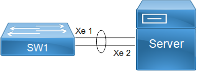
The provided topology diagram consists of a switch and a server (SW1 and server) connected to each other.
SW1: This the central switch in the topology. They are connected through two interfaces (xe1 and xe2).
LACP Aggregator Force-up for Dynamic LAG
To configure LACP Aggregator Force-up for LAG on switch SW1 and Server, follow the steps:
1. Create VLANs and Bridge:
1. Establish a bridge instance (bridge 1) with RSTP as the spanning tree protocol for VLAN-based bridging.
2. Define VLANs 2 to 100 and associate it with (bridge 1) to enable the VLANs for bridging operations, and commit the changes.
SW1(config)# bridge 1 protocol rstp vlan-bridge
SW1(config)# vlan database
SW1(config-vlan)# vlan 2-100 bridge 1 state enable
SW1(config-vlan)# commit
SW1(config-vlan)# exit
2. Configure Port-channel Interface (po1) Aggregate Link between SW1 and Server:
1. Enter configuration mode for Port-channel interface 1 (po1).
2. Configure (po1)as a Layer 2 switchport.
3. Associate (po1) with bridge group 1 so that it operates within the defined bridging context.
4. Set (po1) to trunk mode to carry traffic for multiple VLANs.
5. Configure (po1)to carry traffic for all VLANs, facilitating communication across different VLANs within the network.
6. Configure channel-group 1 for (po1)in active mode for LACP operation:
SW1(config)# interface po1
SW1(config-if)# switchport
SW1(config-if)# bridge-group 1
SW1(config-if)# switchport mode trunk
SW1(config-if)# switchport trunk allowed vlan all
SW1(config-if)# commit
SW1(config-if)# exit
3. Configure the Interfaces (xe1 and xe2):
1. Enter configuration mode for each interface (xe1 and xe2).
2. Assign (xe1 and xe2) to channel-group 1 to participate in the LACP bundle formed by po1, ensuring load balancing and redundancy across member links.
Note: Follow similar steps for SW2, adjusting interface names and configurations accordingly to maintain consistency across the network.
SW1(config)# interface xe1
SW1(config-if)# channel-group 1 mode active
SW1(config-if)# exit
SW1(config)# interface xe2
SW1(config-if)# channel-group 1 mode active
SW1(config-if)# exit
4. Enable LACP Aggregator Force-Up on po1.
SW1(config)# interface po1
SW1(config-if)# lacp agg force-up
SW1(config-if)# commit
SW1(config-if)# exit
LACP Aggregator Force-up for MLAG Configuration
Set up LACP Aggregator Force-Up to maintain network connectivity even when synchronization with the LACP partner is lost on all member links in the MLAG.
Topology
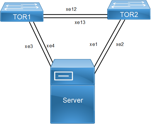
This topology showcases a network setup designed to maximize redundancy, load balancing, and fault tolerance using MLAG and LACP with a Force-Up feature. The network is structured around top-of-rack switches (TOR1 and TOR2).
TOR1 and TOR2 operate as MLAG peers. This setup allows to appear as a single logical switch to connected device (Server).
Traffic can be distributed across the (TOR1 and TOR2), and if one switch fails, the other can handle the load without service interruption. The LACP Aggregator Force-Up feature is enabled to keep port channel member ports operationally up if all member links go down.
This ensures that the remains up, facilitating immediate traffic redirection and avoiding delays associated with LACP negotiation. Both TOR1 and TOR2 connect to server through multiple links, providing path redundancy.If any link or switch fails, the remaining links and switches maintain network connectivity and balance the load, thus avoiding single points of failure.
LACP Aggregator Force-up for MLAG
To configure LACP Aggregator Force-up for MLAG on switches TOR1, and TOR2, follow the steps:
1. Create VLANs and Bridge on TOR1,and TOR2:
1. Establish a bridge instance (bridge 1) with RSTP as the spanning tree protocol for VLAN-based bridging.
2. Define required vlans for example: VLANs 2 to 100 and associate it with (bridge 1) to enable the VLANs for bridging operations, and commit the changes.
TOR1(config)# bridge 1 protocol rstp vlan-bridge
TOR1(config)# vlan database
TOR1(config-vlan)# vlan 2-100 bridge 1 state enable
TOR1(config-vlan)# commit
TOR1(config-vlan)# exit
2. Configure Port Channels (po) as trunk ports allowing all VLANs, and commit the changes: For TORs: Configure interface mlag1,po1,po3 as needed:
1. Enter configuration mode for (mlag1).
2. Configure (mlag1) as a Layer 2 switchport.
3. Associate (mlag1) with bridge group 1 so that it operates within the defined bridging context.
4. Set (mlag1) to trunk mode to carry traffic for multiple VLANs.
TOR1(config)#interface mlag1
TOR1(config-if)#switchport
TOR1(config-if)#bridge-group 1
TOR1(config-if)#switchport mode trunk
TOR1(config-if)#switchport trunk allowed vlan all
TOR1(config-if)#mode active-active
TOR1(config-if)#commit
TOR1(config-if)#exit
5. Configure po1 and map to mlag1.
TOR1(config)#interface po1
TOR1(config-if)#switchport
TOR1(config-if)#mlag 1
TOR1(config-if)#commit
6. Configure po3.
TOR1(config)#interface po3
TOR1(config-if)#switchport
TOR1(config-if)#commit
3. Configure the Interfaces (For TOR1 xe3, xe4, xe12, and xe13, and For TOR2 xe1, xe2, xe12, and xe13):
1. Enter configuration mode for each interface.
2. Assign to channel-group 1 to participate in the LACP bundle formed by po1, ensuring load balancing and redundancy across member links.
3. Configure as a Layer 2 switchport with trunk mode and allow all VLANs to facilitate communication across different VLANs within the network.
TOR1(config)#interface xe3
TOR1(config-if)#channel-group 1 mode active
TOR1(config-if)#exit
TOR1(config)#interface xe4
TOR1(config-if)#channel-group 1 mode active
TOR1(config-if)#commit
TOR1(config-if)#exit
TOR1(config)#interface xe12
TOR1(config-if)#channel-group 3 mode active
TOR1(config-if)#exit
TOR1(config)#interface xe13
TOR1(config-if)#channel-group 3 mode active
TOR1(config-if)#commit
TOR1(config Enable LACP Aggregator Force-up on MLAG interfaces in TOR1 and TOR2:
TOR1(config)#interface mlag1
TOR1(config-if)#lacp agg force-up
TOR1(config-if)#commit
TOR1(config-if)#exit
Note: Similarly, follow the steps to configure mlag1 for TOR2.
Configuration Snapshot
Dynamic LAG:
bridge 1 protocol rstp vlan-bridge
vlan database
vlan 2-4000 bridge 1 state enable
!
interface po1
switchport
bridge-group 1
switchport mode trunk
switchport trunk allowed vlan all
load-interval 30
port-channel load-balance rtag7
lacp agg force-up
!
interface xe1
channel-group 1 mode active
!
interface xe2
channel-group 1 mode active
!
exit
MLAG:
bridge 1 protocol rstp vlan-bridge
vlan database
vlan 2-4000 bridge 1 state enable
!
interface mlag1
switchport
bridge-group 1
switchport mode trunk
switchport trunk allowed vlan all
load-interval 30
lacp agg force-up
!
interface po1
port-channel load-balance rtag7
switchport
mlag 1
!
interface po3
switchport
port-channel load-balance rtag7
!
interface xe3
channel-group 1 mode active
!
interface xe4
channel-group 1 mode active
!
interface xe12
channel-group 3 mode active
!
interface xe13
channel-group 3 mode active
!
exit
!
mcec domain configuration
domain-address 1111.2222.3333
domain-system-number 1
intra-domain-link po3
Dynamic LAG Validation
• Verify agg force-up is enabled in SW1.
SW1#show etherchannel summary
Aggregator po1 100001
Port-channel Force-Up Mode : Activated
Aggregator Type: Layer2
Admin Key: 0001 - Oper Key 0001
Link: xe1 (5034) sync: 0 (agg-force-up)
Link: xe2 (5035) sync: 0 (agg-force-up)
MLAG Validation
• Verify agg force-up is enabled in TOR1.
TOR1#show mlag domain summary
------------------------------------
Domain Configuration
------------------------------------
Domain System Number : 1
Domain Address : 1111.2222.3333
Domain Priority : 32768
Intra Domain Interface : po3
Domain Adjacency : UP
MCEC PDU local version : 1
MCEC PDU peer version : 1
Domain Sync via : Intra-domain-interface
Peer SVI interface MAC Address : 5C.07.58.6F.83.5E
------------------------------------
MLAG Configuration
------------------------------------
MLAG-1
Mapped Aggregator : po1
Physical properties Digest : 54 a9 3a 2a 2b 50 65 bb 3c bc 3d bd c2 43 d6 22
Total Bandwidth : 0
Mlag Sync : IN_SYNC
Mode : Active-Active
Current Mlag state : Standby
Aggregator Force-Up Mode : Activated
TOR1#show etherchannel summary
Aggregator po1 100001
Mlag Force-Up Mode : Activated
Aggregator Type: Layer2
Parent Aggregator : Active mlag1
Admin Key: 16385 - Oper Key 16385
Link: xe3 (5004) sync: 0 (agg-force-up) (Mlag-active-link)
Link: xe4 (5008) sync: 0 (agg-force-up) (Mlag-active-link)
--------------------------------------
Aggregator po3 100003
Aggregator Type: Layer2
Admin Key: 0003 - Oper Key 0003
Link: xe12 (5011) sync: 1
Link: xe13 (5015) sync: 1
Implementation Examples
Dynamic Port-Channel configuration:
Both interfaces in the dynamic port-channel must support force-up to allow the server to boot using any connected link.
During the server’s boot stage, the force-up feature ensures that any one of the connected interfaces can be used to initiate and complete the boot process, while the other interface remains inactive until LACP communication is established.
MLAG Configuration Requirement:
To support network booting, the MLAG domain is configured with LACP force-up. This allows at least one link to become active, ensuring the server can boot over the network.
Typically, all interfaces (xe1, xe2, xe3, xe4) need to be prepared to provide force-up capabilities to handle server booting flexibility.
Traffic Management:
When in force-up state, each interface operates as an individual bridge-port.
CLI Commands
The LACP aggregator force-up feature introduces the lacp agg force-up configuration command.
lacp agg force-up
Use this command to configure Aggregator Force-up on Dynamic LAG or Dynamic MLAG interface.
If this command is enabled and LACP Partner sync is not established on any of the member links in Aggregator then, all the member links will enter Aggregator Force-up state in which they will act like individual bridge ports with respect to Layer2 Learning, Flooding, or Forwarding. Once LACP Partner sync is established on atleast one member link, the members will exit Aggregator Force-up and become part of the LAG that is normal LAG functioning is retained.
Use no lacp agg force-up parameter of this command to disable the aggregator force-up state.
Command Syntax
lacp agg force-up
no lacp agg force-up
Parameters
None
Default
Disabled
Command Mode
Interface mode
Applicability
Introduced the lacp agg force-up parameter in the OcNOS version 6.5.2.
Example
The following sequence of commands is used to configure the LACP Aggregator Force-Up feature in MLAG:
#configure terminal
(config)#interface mlag1
(config-if)#lacp agg force-up
(config-if)#exit
The following sequence of commands is used to configure the LACP Aggregator Force-Up feature in Dynamic LAG:
#configure terminal
(config)#interface po1
(config-if)#lacp agg force-up
(config-if)#exit
Glossary
The following provides definitions for key terms or abbreviations and their meanings used throughout this document:
Key Terms/Acronym | Description |
Link Aggregation Control Protocol (LACP) | A protocol provides a way to bundle several physical ports together to form a single logical channel for the purpose of increasing bandwidth and providing redundancy. |
Aggregator | A group of physical interfaces that are combined into a single logical interface (known as a port channel or link aggregation group) for load balancing and redundancy. |
Aggregator Force-Up | A feature that keeps the members of LACP aggregator (port channel) operationally up, even if all member links are down. This is typically used in scenarios where there is server boot up. |
Multi-Chassis Link Aggregation Group (MLAG) | Creation of a single logical link aggregation group across two separate switches, providing redundancy and load balancing across multiple chassis. |
Port Channel (Po) | A logical grouping of multiple physical network interfaces, combined to act as a single interface. This allows for increased bandwidth and redundancy. |
Active Mode | In LACP, active mode means the device actively initiates LACP negotiations and participates in the formation of LACP port channels. |
Passive Mode | In LACP, passive mode means the device only responds to LACP packets but does not initiate the formation of LACP port channels. |