Ethernet Linear Protection Switching Configuration
The feature Ethernet Linear Protection Switching (ELPS) adds a fast mechanism to switch from a failing Ethernet transport entity to a working Ethernet transport entity, thereby restoring node to node link up condition.
The objective of fast protection switching is achieved by integrating mature Ethernet operations, administration, and maintenance (OAM) functions and a simple automatic protection switching (APS) protocol for Ethernet linear networks. Since protection switching requires monitoring of both working and protection transport enti-ties, it is required that MEPs be activated for the purpose of monitoring the working and protection transport entities. Both transport entities are monitored individually by exchanging Continuity Check Messages (CCMs).
ELPS protocol is optimized to provide Protection Switching between two distinct endpoints on a point to point vlan-based Ethernet network. It can be used as an alternative to spanning tree protocol (STP) for fast transiting the port status without complex computation, provisioning overhead, and excessive information exchange, to thus achieve much faster (i.e., 50ms) protection switching. With ELPS, it is much convenient for network operator to grasp the status of network (eg. Active network topology) with protection switching than with other survivability mechanisms, such as STP.
Note: A loop-breaking mechanism (such as STP or ELPS) must be present at all times. If a loop exists before ELPS
Limitations
• 1:1 is supported for sub interfaces over cross-connect.
• Supported on both Q1 and Q2 devices.
• CLI restructure: Make CLI more modular and flexible.
• Make ELPS control plane code bridge independent.
In the linear 1:1 protection switching architecture, the protection transport entity is dedicated to the working transport entity. However, the normal traffic signal is transported either on the working transport entity or on the protection transport entity using a selector bridge at the source of the protected domain.
Prerequisite
The prerequisites for implementing G.8031 with cross-connects are:
• Devices in the network (for example, routers and switches) must support G.8031 with cross connect and relevant traffic generation features.
• A network path configured for test traffic between source and destination endpoints.
• CFM down mep should configured between the devices.
Note: The initial Layer 2 movement will take some time to settle after configuring ELPS.
Topology
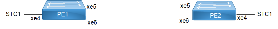
ELPS Topology
Configuration
Prerequisite
Configure below hardware-profile commands related to CFM in configuration mode and reboot the nodes.
hardware-profile filter cfm-domain-name-str enable
hardware-profile statistics cfm-ccm enable
PE1 Configurations
Interface Configuration: Configure L2 sub-interface with encapsulation type dot1q/dot1ad on node as mentioned below:
Access-interface configuration:
interface xe4
speed 10g
!
interface xe4.100 switchport
encapsulation dot1q 100
load-interval 30
Network interface configuration:
interface xe5
speed 10g
!
interface xe5.100 switchport
encapsulation dot1q 100
load-interval 30
!
interface xe6
speed 10g
!
interface xe6.100 switchport
encapsulation dot1q 100
load-interval 30
G8031 ELPS Configuration:
1. Configure g8031 eps-protection group with working-port and protection-port as mentioned below:
g8031 eps-protection group PG12
working-port xe5.100
protection-port xe6.100
protection-port xe6.100
2. Configure g8031 profile with mode as one-and-one-bidirectional (1:1) and swith mode as revertive/non-revertive on node as below:
g8031 profile profile1
mode one-and-one-bidirectional
switching mode revertive
3. Configure g8031 eps-instance with eps-protection group, g8031 profile, aps-channel level and control vlan on node as below:
g8031 eps-instance eps12
eps-protection-group PG12
g8031-profile profile1
aps-channel level 7
control vlan 100
!
4. CFM Configuration: Configure Ethernet CFM down mep using g8031 eps-protection group working-port (xe5.100) and protection-ports (xe6.100) on node as mentioned below:
ethernet cfm domain-type character-string domain-name AB001 level 7 mip-creation none
service ma-type string ma-name ma01
ethernet cfm mep down mpid 102 active true xe5.100 vlan 100
cc multicast state enable
exit-ether-ma-mep-mode
mep crosscheck mpid 201
cc interval 3ms
exit-ether-ma-mode
service ma-type string ma-name ma02
ethernet cfm mep down mpid 112 active true xe6.100 vlan 100
cc multicast state enable
exit-ether-ma-mep-mode
mep crosscheck mpid 211
cc interval 3ms
exit-ether-ma-mode
5. Cross-connect Configuration: Configure cross-connect using g8031 protection-group working-port and protection-port as backup port and map the elps instance as mentioned below:
cross-connect 100
interface xe5.100
backup xe6.100
g8031-eps eps12
interface xe4.100
PE2 Configurations:
1. Interface Configuration: Configure L2 sub-interface with encapsulation type dot1q/dot1ad on node as mentioned.
2. Access-interface configuration: Enter the interface xe4 and set the interface speed to 10G.
interface xe4
speed 10g
!
3. Configure VLAN sub-interface xe4.100, and then exit the interface mode.
interface xe4.100 switchport
encapsulation dot1q 100
load-interval 30
exit
4. Configure Network Interfaces (xe5): Enter interface xe5 and set the speed to 10G.
5. Configure VLAN sub-interface xe5.100.
interface xe5.100 switchport
encapsulation dot1q 100
load-interval 30
6. Configure Network Interfaces (xe6): Enter interface xe6 and set the speed to 10G.
interface xe6.100 switchport
encapsulation dot1q 100
load-interval 30
7. Configure VLAN sub-interface xe6.100.
interface xe6.100 switchport
encapsulation dot1q 100
load-interval 30
G8031 ELPS Configuration:
1. Configure G.8031 EPS-Protection Group: Define the EPS-protection group with the specified working and protection ports.
g8031 eps-protection group PG12
working-port xe5.100
protection-port xe6.100
2. Configure G.8031 Profile: Set up the G.8031 profile with the required mode and switching configuration.
g8031 profile profile1
mode one-and-one-bidirectional
switching mode revertive
3. Configure G.8031 EPS-Instance: Associate the EPS-instance with the previously defined protection group and profile. Also, configure the APS-channel level and control VLAN:
g8031 eps-instance eps12
eps-protection-group PG12
g8031-profile profile1
aps-channel level 7
control vlan 100
Ethernet Connectivity Fault Management (CFM) Configuration
1. Configured Ethernet CFM down mep using g8031 eps-protection group working-port (xe5.100) and protection-ports (xe6.100) on node as mentioned below.
2. Configure the CFM Domain: Define the CFM domain with the required domain type, name, and level.
ethernet cfm domain-type character-string domain-name AB001 level 7 mip-creation none
3. Configure CFM Service and Maintenance Association (MA): For MA01 on Interface xe5.100.
4. Define the CFM service with the MA name ma01, and configure the Maintenance Endpoint (MEP).
service ma-type string ma-name ma01
ethernet cfm mep down mpid 201 active true xe5.100 vlan 100
5. Enable Continuity Check (CC) Multicast Stat and then configure MEP Crosscheck.
cc multicast state enable
exit-ether-ma-mep-mode
mep crosscheck mpid 102
6. Set the Continuity Check (CC) Interval.
cc interval 3ms
exit-ether-ma-mode
7. Configure CFM Service and Maintenance Association (MA): For MA02 on Interface xe6.100.
service ma-type string ma-name ma02
8. Define the CFM service with the MA name ma02, and then configure the MEP.
ethernet cfm mep down mpid 211 active true xe6.100 vlan 100
9. Enable Continuity Check (CC) Multicast State, and then configure MEP Crosscheck:
cc multicast state enable
exit-ether-ma-mep-mode
mep crosscheck mpid 112
10. Set the Continuity Check (CC) Interval.
cc interval 3ms
exit-ether-ma-mode
Cross-connect Configuration
Configure cross-connect using g8031 protection-group working-port and protection-port as backup port and map the ELPS instance as mentioned below.
1. Configure Cross-Connect ID: Define the cross-connect ID, and then assign interface xe5.100 as the primary interface.
cross-connect 100
interface xe5.100
2. Set interface xe6.100 as the backup interface, associate the G.8031 EPS instance (eps12)
backup xe6.100
g8031-eps eps12
3. Assign interface xe4.100 to the cross-connect.
interface xe4.100
Validation
PE1 node
:
Verify ELPS instance status using below command.
PE1#show g8031 eps-instance
EPS-Name Id Mode Working-Path State Protection-Path State Control-VLAN CFM
-----------------------------------------------------------------------------------------------
eps12 1 1:1,BI xe5.100 (A) Up xe6.100 Up 100 Yes
PE1#
PE1#show g8031 eps-instance eps12
Inst Name : eps12 (1), Profile (profile1), Protection Group (PG12)
Mode & Group : Bridge (1:1), Direction (Bi), Revertive (Yes)
: Working port (po1.100, Up) Protection port (xe5.100, Up)
Current State : No Request, Request signal (Null), Active-Path (Working)
dFOP State - Not in defect mode
working_cfm : mep_id (102), cc-interval (3ms), Domain (AB001), MA (ma01)
Protection_cfm : mep_id (112), cc-interval (3ms), Domain (AB001), MA (ma02)
APS channel Info: vlan (100) Level (7)
APS Statistics : Tx - 11 Rx - 6
PE1#
CFM status using below command
DUT1#show ethernet cfm maintenance-points count
--------------------------------------------
Total No of MIPs : 0
Total No of MEPs : 2
Total No of UP MEPs : 0
Total No of Down MEPs : 2
Total No of Active MEPs : 2
Total No of UP CCM sessions : 2
Total No of Active Test sessions : 0
Total No of Active LM sessions : 0
Total No of Active DM sessions : 0
--------------------------------------------
DUT1#
DUT1#show ethernet cfm errors
Domain Name MA Name Level VLAN InnerVLAN MEPID Defects
-----------------------------------------------------------------------
AB001 ma01 7 100 NA 102 .....
AB001 ma02 7 100 NA 112 .....
1. defRDICCM 2. defMACstatus 3. defRemoteCCM
4. defErrorCCM 5. defXconCCM
DUT1#