Y.1731 and CFM Over VXLAN ELAN Multi Home
Overview
The Multi Home VxLAN ELAN Y.1731 CFM over Sub-interface feature enables the monitoring and management of Virtual Extensible LAN (VxLAN) Ethernet LAN services using the Y.1731 Connectivity Fault Management (CFM) protocol over sub-interfaces. This feature enhances fault detection and performance monitoring capabilities for VxLAN E-LAN services, allowing network operators to ensure high availability and reliability of their networks. By extending Y.1731 CFM functionality to sub-interfaces in single home VxLAN E-LAN deployments, this feature provides comprehensive end-to-end visibility and control, enabling proactive fault detection, isolation, and troubleshooting.
CFM multi-homing allows Customer Edge (CE) device to connect more than one Provider Edge (PE) device. Multi-homing ensures redundant connectivity. The redundant PE device ensures that there is no traffic disruption when there is a network failure.
Feature Characteristics
• Utilizes sub-interfaces to partition Ethernet traffic within the Multi Home VxLAN ELAN architecture, enabling efficient service delivery and management.
• Implements VxLAN ELAN architecture with multi-homing capabilities, facilitating the creation of Virtual Extensible LAN (VxLAN) with simplified configurations and reduced complexity.
• Provides robust fault detection mechanisms to identify connectivity issues, link failures, and service disruptions in Ethernet networks.
Benefits
• Provides detailed insights into Ethernet service performance, enabling proactive monitoring and optimization of network resources.
• Minimizes service downtime by promptly detecting and resolving faults, ensuring uninterrupted service delivery and customer satisfaction.
• Optimizes network resource utilization and bandwidth allocation by identifying and addressing connectivity issues in a timely manner.
• Facilitates rapid fault identification and isolation, accelerating troubleshooting processes and reducing mean time to repair (MTTR).
• Ensures compliance with Service Level Agreements (SLAs) by maintaining service quality metrics within defined thresholds and objectives.
Prerequisites
Ensure that the network devices (routers, switches) support Y.1731 CFM functionality and Multi- Home VxLAN ELAN configuration.
Verify that the devices are running compatible software versions that include support for these features.
Configuration
Configure Multi- Home VxLAN ELAN Y.1731 CFM over Sub-interface for enhanced fault management in VxLAN networks.
Topology
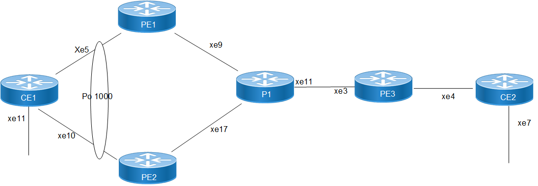
The topology consists of two Customer Edge devices (CE1 and CE2) connected to Provider Edge devices (PE1,PE2, and PE3) through sub-interfaces. The Provider Edge devices are interconnected through Provider device (P1).
Y.1731 functionality is implemented over these sub-interfaces, allowing for fault detection and performance monitoring of Ethernet connectivity between the customer sites.
VXLAN ELAN-Multi Home
Perform the following configurations to configure Multihome Home VxLAN ELINE Y.1731 CFM over Sub-interface:
Customer Edge (CE) Nodes Configuration (CE1, CE2):
1. Configure the interface xe1 and set load interval of (30 seconds):
CE1(config)#interface xe11
CE1(config-if)# switchport
CE1(config-if)#load-interval 30
CE1(config-if)#commit
CE1(config-if)#exit
2. Configure Port-Channel interface:
CE1(config)#interface po1000
CE1(config-if)# switchport
CE1(config-if)# load-interval 30
CE1(config-if)#commit
3. Assign physical interfaces to Port-Channel:
CE1(config)#interface xe5
CE1(config-if)# channel-group 1000 mode active
CE1(config-if)#commit
CE1(config-if)#exit
CE1(config)#interface xe10
CE1(config-if)# channel-group 1000 mode active
CE1(config-if)#commit
CE1(config-if)#exit
4. Create sub-interface po1000.100 and xe11.100 adding the VLAN:
CE1(config)#interface po1000.100 switchport
CE1(config-if)#encapsulation dot1q 100
CE1(config-if)#commit
CE1(config-if)#exit
CE1(config)#interface xe11.100 switchport
CE1(config-if)#encapsulation dot1q 100
CE1(config-if)#commit
5. Set up a cross-connect named (MH1),specifying in and out interfaces:
CE1(config)#cross-connect MH1
CE1(config-xc)#interface xe11.100
CE1(config-xc)#interface po1000.100
CE1(config-xc)#commit
6. On CE2 Node, configure the interface xe4 and xe7 switchport and set load interval 30seconds):
CE2(config)#interface xe4
CE2(config-if)# switchport
CE2(config-if)#load-interval 30
CE2(config-if)#commit
CE2(config-if)#exit
CE2(config)#interface xe7
CE2(config-if)# switchport
CE2(config-if)#load-interval 30
CE2(config-if)#commit
CE2(config-if)#exit
7. Create sub-interface (xe4.100) and (xe7.100) adding the VLAN 100:
CE2(config)#interface xe4.100 switchport
CE2(config-if)#encapsulation dot1q 100
CE2(config-if)#commit
CE2(config-if)#exit
CE2(config)#interface xe7.100 switchport
CE2(config-if)#encapsulation dot1q 100
CE2(config-if)#commit
CE2(config-if)#exit
8. Set up a cross-connect named (SH1),specifying in and out interfaces:
CE2(config)#cross-connect SH1
CE2(config-xc)#interface xe4.100
CE2(config-xc)#interface xe7.100
CE2(config-xc)#commit
Provider Edge (PE) & Provider (P) Router Configuration:
1. Configure CFM and VXLAN related hardware profiles:
PE1(config)# hardware-profile filter cfm-domain-name-str enable
PE1(config)# hardware-profile statistics cfm-lm enable
PE1(config)# hardware-profile statistics cfm-ccm enable
PE1(config)# hardware-profile statistics cfm-slm enable
Note:
• In Q2 devices, hardware-profile filter cfm-domain-name-str enable by default.
• Perform the same Port-Channel configuration on PE2 router, changing the interface numbers accordingly.
2. Configure the loopback interface with a secondary IP address (1.1.1.1/32):
PE1(config)#interface lo
PE1(config-if)#ip address 1.1.1.1/32 secondary
PE1(config-if)#commit
PE1(config-if)#exit
Note: Configure loopback and interface IP addresses on PE2 using the respective values assigned.
3. Configure network interface as xe9 with an IP address (192.168.10.1/24):
PE1(config)#interface xe9
PE1(config-if)#load-interval 30
PE1(config-if)#ip address 192.168.10.1/24
PE1(config-if)#label-switching
PE1(config-if)#commit
PE1(config-if)#exit
4. Configure OSPF routing, specify the OSPF router ID as (1.1.1.1), enable BFD on all interfaces, define the network (1.1.1.1/32) in area (0.0.0.0), and define the network (192.168.10.0/24):
PE1(config)#router ospf 1
PE1(config-router)#ospf router-id 1.1.1.1
PE1(config-router)#bfd all-interfaces
PE1(config-router)#network 1.1.1.1/32 area 0.0.0.0
PE1(config-router)#network 192.168.10.0/24 area 0.0.0.0
PE1(config-router)#commit
PE1(config-router)#exit
Note: Modify the OSPF router ID and networks on PE2 with unique IP address.
5. Enable VxLAN globally and configure VTEP IP:
PE1(config)# nvo vxlan enable
PE1(config)# evpn vxlan multihoming enable
PE1(config)#evpn esi hold-time 100
PE1(config)# nvo vxlan vtep-ip-global 1.1.1.1
PE1(config)# commit
Note: Apply VXLAN settings with PE2 corresponding VTEP IP address.
6. Configure BGP with the remote PE devices and activate EVPN:
PE1(config)# router bgp 100
PE1(config-router)# neighbor 3.3.3.3 remote-as 100
PE1(config-router)# neighbor 3.3.3.3 update-source lo
PE1(config-router)# address-family l2vpn evpn
PE1(config-router-af)# neighbor 3.3.3.3 activate
PE1(config-router-af)# exit
PE1(config-router)# exit
PE1(config)# commit
Note: Modify the BGP neighbor configurations on PE2 to establish correct peering with other routers.
7. Configure MAC VRF with the appropriate RD and RT:
PE1(config)#mac vrf vrf10
PE1(config-vrf)# rd 1.1.1.1:10
PE1(config-vrf)# route-target both 10:10
PE1(config-vrf)#commit
PE1(config-vrf)#exit
8. Map the VxLAN instance and VRF, specifying the VxLAN ID:
PE1(config)# nvo vxlan id 2000 ingress-replication
PE1(config-nvo)# vxlan host-reachability-protocol evpn-bgp vrf10
PE1(config-nvo)#vni-name MH
PE1(config-nvo)#commit
Note: VXLAN and BGP configurations align across all PE routers with respective neighbor modifications.
9. Configure the PO interface with ESI MAC.
PE1(config)#interface po1000
PE1(config-if)# switchport
PE1(config-if)# load-interval 30
PE1(config-if)# evpn multi-homed system-mac 0000.aaaa.bbbb
PE1(config-if-es)#
PE1(config-if-es)#commit
Note: Provide the similar configurations for PE2.
10. Add the interface into PO
PE1(config)# interface po1000.100 switchport
PE1(config-if)# encapsulation dot1q 100
PE1(config-if)# access-if-evpn
PE1(config-acc-if-evpn)#map vpn-id 2000
PE1(config-acc-if-evpn)# commit
Note: Provide the similar configurations for PE2.
11. Configure CFM UP MEP on PE1, define the CFM domain (MD001), create MA, configure UP MEP, andconfigure Remote MEP Auto-discovery enable, set CC Interval 10ms:
PE1(config)#ethernet cfm domain-type character-string domain-name MD001
level 6 mip-creation default
PE1(config-ether-cfm)#service ma-type string ma-name ma1
PE1(config-ether-cfm-ma)#ethernet cfm mep up mpid 50 active true
po1000.100 vlan 100
po1000.100 vlan 100
PE1(config-ether-cfm-ma-mep)#cc multicast state enable
PE1(config-ether-cfm-ma-mep)#exit-ether-ma-mep-mode
PE1(config-ether-cfm-ma)#rmep auto-discovery enable
PE1(config-ether-cfm-ma)#cc interval 10ms
PE1(config-ether-cfm-ma)#exit-ether-ma-mode
PE1(config-ether-cfm)#commit
Note:
• Similarly, configure the UP MEP CFM for PE2 router with different MEP id.
• Similarly, configure the UP MEP CFM for PE3 router with different MEP id and SLM and DMM reply configurations:
PE3(config)#ethernet cfm domain-type character-string domain-name MD001 level 6 mip-creation default
PE3(config-ether-cfm)#service ma-type string ma-name ma1
PE3(config-ether-cfm-ma)#ethernet cfm mep up mpid 52 active true xe4.100 vlan 100
PE3(config-ether-cfm-ma-mep)#cc multicast state enable
PE3(config-ether-cfm-ma-mep)#ethernet cfm loss-measurement reply slm
PE3(config-ether-cfm-ma-mep)#ethernet cfm delay-measurement reply dmm
PE3(config-ether-cfm-ma-mep)#exit-ether-ma-mep-mode
PE3(config-ether-cfm-ma)#rmep auto-discovery enable
PE3(config-ether-cfm-ma)#cc interval 10ms
PE3(config-ether-cfm-ma)#exit-ether-ma-mode
PE3(config-ether-cfm)#commit
12. Provide SLM and DM profile configuration, define a delay measurement profile named DM, set the measurement interval to 1 second, specify the number of intervals stored as 2, configure the message period as 1 second, set the loss measurement type to SLM, set the measurement interval to 1 second, specify the number of intervals stored as 3.
PE1(config)# ethernet cfm delay-measurement profile-name DM
PE1(config-cfm-dm)# measurement-interval 1
PE1(config-cfm-dm)# intervals-stored 2
PE1(config-cfm-dm)# message-period 1s
PE1(config-cfm-dm)# commit
PE1(config)# ethernet cfm loss-measurement profile-name SLM
PE1(config-cfm-lm)# measurement-type slm
PE1(config-cfm-lm)# measurement-interval 1
PE1(config-cfm-lm)# intervals-stored 3
PE1(config-cfm-lm)# message-period 1s
PE1(config-cfm-lm)# commit
Note: Modify the delay measurement profile on PE2 router.
Configuration Snapshot:
CE1:
interface xe11
switchport
load-interval 30
!
interface po1000
switchport
load-interval 30
!
interface xe5
channel-group 1000 mode active
!
interface xe10
channel-group 1000 mode active
!
interface po1000.100 switchport
encapsulation dot1q 100
!
interface xe11.100 switchport
encapsulation dot1q 100
!
cross-connect MH
interface xe11.100
interface po1000.100
!
CE2:
interface xe4
switchport
load-interval 30
!
interface xe7
switchport
load-interval 30
!
interface xe4.100 switchport
encapsulation dot1q 100
!
interface xe7.100 switchport
encapsulation dot1q 100
!
cross-connect SH1
interface xe4.100
interface xe7.100
!
PE1:
hardware-profile filter cfm-domain-name-str enable
hardware-profile statistics cfm-lm enable
hardware-profile statistics cfm-ccm enable
hardware-profile statistics cfm-slm enable
interface lo
ip address 1.1.1.1/32 secondary
!
interface xe9
load-interval 30
ip address 192.168.10.1/24
label-switching
!
router ospf 1
ospf router-id 1.1.1.1
bfd all-interfaces
network 1.1.1.1/32 area 0.0.0.0
network 192.168.10.0/24 area 0.0.0.0
!
nvo vxlan enable
!
evpn esi hold-time 100
!
evpn vxlan multihoming enable
!
nvo vxlan vtep-ip-global 1.1.1.1
!
router bgp 100
neighbor 3.3.3.3 remote-as 100
neighbor 3.3.3.3 update-source lo
address-family l2vpn evpn
neighbor 3.3.3.3 activate
!
mac vrf vrf10
rd 1.1.1.1:10
route-target both 10:10
!
nvo vxlan id 2000 ingress-replication
vxlan host-reachability-protocol evpn-bgp vrf10
vni-name MH
!
interface po1000
switchport
load-interval 30
evpn multi-homed system-mac 0000.aaaa.bbbb
!
interface xe5
channel-group 1000 mode active
!
interface po1000.100 switchport
encapsulation dot1q 100
access-if-evpn
map vpn-id 2000
!
ethernet cfm domain-type character-string domain-name MD001 level 6 mip-creation default
service ma-type string ma-name ma1
ethernet cfm mep up mpid 50 active true po1000.100 vlan 100
cc multicast state enable
exit-ether-ma-mep-mode
rmep auto-discovery enable
cc interval 10ms
exit-ether-ma-mode
!
ethernet cfm delay-measurement profile-name DM
measurement-interval 1
intervals-stored 2
message-period 1s
!
ethernet cfm loss-measurement profile-name SLM
measurement-type slm
measurement-interval 1
intervals-stored 3
message-period 1s
!
PE2:
hardware-profile filter cfm-domain-name-str enable
conhardware-profile statistics cfm-lm enable
hardware-profile statistics cfm-ccm enable
hardware-profile statistics cfm-slm enable
!
interface lo
ip address 2.2.2.2/32 secondary
!
interface xe17
load-interval 30
ip address 192.168.20.1/24
label-switching
!
router ospf 1
ospf router-id 2.2.2.2
bfd all-interfaces
network 2.2.2.2/32 area 0.0.0.0
network 192.168.20.0/24 area 0.0.0.0
!
nvo vxlan enable
!
evpn esi hold-time 100
!
evpn vxlan multihoming enable
!
nvo vxlan vtep-ip-global 2.2.2.2
!
router bgp 100
neighbor 3.3.3.3 remote-as 100
neighbor 3.3.3.3 update-source lo
address-family l2vpn evpn
neighbor 3.3.3.3 activate
!
mac vrf vrf10
rd 2.2.2.2:10
route-target both 10:10
!
nvo vxlan id 2000 ingress-replication
vxlan host-reachability-protocol evpn-bgp vrf10
vni-name MH
!
interface po1000
switchport
load-interval 30
evpn multi-homed system-mac 0000.aaaa.bbbb
!
interface xe5
channel-group 1000 mode active
!
interface po1000.100 switchport
encapsulation dot1q 100
access-if-evpn
map vpn-id 2000
!
ethernet cfm domain-type character-string domain-name MD001 level 6 mip-creation default
service ma-type string ma-name ma1
ethernet cfm mep up mpid 51 active true po1000.100 vlan 100
cc multicast state enable
exit-ether-ma-mep-mode
rmep auto-discovery enable
cc interval 10ms
exit-ether-ma-mode
!
P1:
interface lo
ip address 4.4.4.4/32 secondary
!
interface xe9
load-interval 30
ip address 192.168.10.2/24
label-switching
!
interface xe17
load-interval 30
ip address 192.168.20.2/24
label-switching
!
interface xe11
load-interval 30
ip address 192.168.30.1/24
label-switching
!
router ospf 1
ospf router-id 4.4.4.4
bfd all-interfaces
network 4.4.4.4/32 area 0.0.0.0
network 192.168.10.0/24 area 0.0.0.0
network 192.168.20.0/24 area 0.0.0.0
network 192.168.30.0/24 area 0.0.0.0
!
PE3:
hardware-profile filter cfm-domain-name-str enable
hardware-profile statistics cfm-lm enable
hardware-profile statistics cfm-ccm enable
hardware-profile statistics cfm-slm enable
!
interface lo
ip address 3.3.3.3/32 secondary
!
interface xe3
load-interval 30
ip address 192.168.30.2/24
label-switching
!
router ospf 1
ospf router-id 3.3.3.3
bfd all-interfaces
network 3.3.3.3/32 area 0.0.0.0
network 192.168.30.0/24 area 0.0.0.0
!
nvo vxlan enable
!
evpn esi hold-time 100
!
nvo vxlan vtep-ip-global 3.3.3.3
!
router bgp 100
neighbor 1.1.1.1 remote-as 100
neighbor 1.1.1.1 update-source lo
neighbor 2.2.2.2 remote-as 100
neighbor 2.2.2.2 update-source lo
address-family l2vpn evpn
neighbor 1.1.1.1 activate
neighbor 2.2.2.2 activate
!
mac vrf vrf10
rd 3.3.3.3:10
route-target both 10:10
!
nvo vxlan id 2000 ingress-replication
vxlan host-reachability-protocol evpn-bgp vrf10
vni-name SH
!
interface xe4
switchport
load-interval 30
!
interface xe4.100 switchport
encapsulation dot1q 100
access-if-evpn
map vpn-id 2000
!
ethernet cfm domain-type character-string domain-name MD001 level 6 mip-creation default
service ma-type string ma-name ma1
ethernet cfm mep up mpid 52 active true xe4.100 vlan 100
cc multicast state enable
ethernet cfm loss-measurement reply slm
ethernet cfm delay-measurement reply dmm
exit-ether-ma-mep-mode
rmep auto-discovery enable
cc interval 10ms
exit-ether-ma-mode
!
Validation
Verify the nvo vxlan status:
PE1#show nvo vxlan
VXLAN Information
=================
Codes: NW - Network Port
AC - Access Port
(u) - Untagged
VNID VNI-Name VNI-Type Type Interface ESI VLAN DF-Status Src-Addr Dst-Addr
_______________________________________________________________________________________________________________________________
2000 ---- L2 NW ---- ---- ---- ---- 1.1.1.1 3.3.3.3
2000 ---- -- AC po1000.100 00:00:00:aa:aa:bb:bb:00:00:00 ---- DF ---- ----
Total number of entries are 2
Note: Refer sub-interface config for VLAN information.
Verify the CFM Errors Status:
PE1#show ethernet cfm errors domain MD001
Domain Name MA Name Level VLAN InnerVLAN MEPID Defects
-----------------------------------------------------------------------
MD001 ma1 6 100 NA 50 ....
Verify the ethernet cfm ma status domain is active or not::
PE1#show ethernet cfm ma status domain MD001 ma-name ma1
MA NAME STATUS
-------------------------------
ma1 Active
Verify the local MEP is installed or not:
PE1#show ethernet cfm maintenance-points local mep domain MD001 ma-name ma1
MPID Dir Lvl VLAN CC-Stat HW-Status CC-Intvl MAC-Address Def Port MD Name
--------------------------------------------------------------------------------
50 Up 6 100 Enable Installed 10 ms e8c5.7afe.fae9 F xe3.10 MD001
Verify the RMEP is learned or not:
PE1#show ethernet cfm maintenance-points remote domain MD001 ma-name ma1
MA_NAME MEPID RMEPID LEVEL Rx CCM RDI PEER-MAC TYPE
------------------------------------------------------------------------------
ma1 50 52 6 Yes False 5c07.5851.cfad Learnt
Verify the Ping:
PE1#ping ethernet mac 5c07.5851.cfad unicast source 50 domain MD001 ma ma1
success rate is 100 (5/5)
Verify the traceroute:
PE1#traceroute ethernet 5c07.5851.cfad mepid 50 domain MD001 ma ma1
MP Mac Hops Relay-action Ingress/Egress Ingress/Egress action
5c07.5851.cfad 1 RlyHit Ingress IngOK
Verify the Delay-measurement:
PE1#delay-measurement type proactive profile-name DM rmep 52 mep 50 domain MD001 ma ma11
PE1#2025 Feb 07 14:49:08.416 : PE1 : ONMD : INFO : [CFM_PM_SESSION_INFO_5]: CFM Frame
Delay Measurement session started for MEP Id 50 and RMEP Id 52
PE1#
PE1#show ethernet cfm delay-measurement mep 50 domain MD001 ma-name ma1
MD : MD001
MA : ma1
MEP : 50
VLAN ID : 100
Interface : po1000.100
Peer MAC Address : 5c07.5851.cfad
CURRENT:
======================
RMEP ID : 210
Measurement ID : 1
Measurement Type : DMM
Elapsed time(sec) : 12
Start Time : 2025 Feb 07 14:49:08
Suspect Flag : FALSE
Min Frame Delay(usec) : 20
Max Frame Delay(usec) : 21
Avg Frame Delay(usec) : 20
Min Inter FD Variation(usec): 0
Max Inter FD Variation(usec): 1
Avg Inter FD Variation(usec): 0
FRAME DELAY BINS
Bin Number Bin Threshold(usec) Bin Counter
========================================================
1 0 - < 4999 12
2 5000 - < 9999 0
3 10000 - < 4294967295 0
INTER-FRAME DELAY BINS
Bin Number Bin Threshold(usec) Bin Counter
========================================================
1 0 - < 4999 11
2 5000 - < 4294967295 0
Verify the SLM:
PE1#loss-measurement type proactive profile-name SLM rmep 52 mep 50 domain MD001 ma ma1
PE1#2025 Feb 07 14:53:24.850 : PE1 : ONMD : INFO : [CFM_DEFECT_INFO_5]: CFM Frame Loss
Measurement started for MEP:50 MA:ma1 MD:MD001
PE1#show ethernet cfm loss-measurement mep 50 domain MD001 ma-name ma1
CURRENT:
Measurement ID : 2
Suspect : False
Measurement Type : slm
Elapsed time(sec) : 10
Start Time : 2025 Feb 15:03:43:02
Near End loss : 0
Far End loss : 0
Near End accumulated loss : 0
Far End accumulated loss : 0
Near End frame loss ratio : 0
Far End frame loss ratio : 0
HISTORY:
Measurement ID : 1
Suspect : False
Measurement Type : slm
Elapsed time(sec) : 60
End Time : 2025 Feb 15:03:43:02
Near End loss : 0
Far End loss : 0
Near End accumulated loss : 0
Far End accumulated loss : 0
Near End frame loss ratio : 0
Far End frame loss ratio : 0
Near End frame loss ratio min : 0
Far End frame loss ratio min : 0
Near End frame loss ratio max : 0
Far End frame loss ratio max : 0
Implementation Examples
Enterprise Connectivity Monitoring:
Scenario: A large enterprise operates multiple branch offices connected via Ethernet services provided by a service provider network.
Use Case: Y.1731 CFM over sub-interface using Single Home VxLAN enables the enterprise to monitor theconnectivity and performance of its branch office connections. It facilitates proactive fault detection and management, ensuring reliable and uninterrupted communication between the headquarters and branch offices.
Service Provider Network Operations:
Scenario: A service provider manages a diverse range of Ethernet services for its enterprise customers, including VPNs, Internet access, and cloud connectivity.
Use Case: Y.1731 CFM over sub-interface using Single Home VxLAN empowers the service provider to deliverhigh-quality Ethernet services with enhanced fault management capabilities. It enables the provider to quickly identify and resolve connectivity issues, minimize service downtime, and maintain customer satisfaction.
Glossary
The following provides definitions for key terms or abbreviations and their meanings used throughout this document:
Key Terms/Acronym | Description |
Y.1731 | A standard defined by the International Telecommunication Union Telecommunication Standardization Sector (ITU-T) that specifies performance monitoring and fault management for Ethernet-based networks. |
Sub-interface | A logical division of a physical interface, typically used to separate traffic based on VLAN or other criteria. In this context, sub-interfaces are employed to establish distinct connections within the VxLAN ELAN SH topology. |
ELAN | ELAN is a type of VxLAN service that provides point-to-multi point Ethernet connectivity between two sites. |
Single Home (SH) | Refers to the configuration where a Customer Edge device (CE) is connected to only one Provider Edge device (PE) within an VxLAN setup. It contrasts with the multi-homed configuration, where a CE may be connected to multiple PEs. |
Maintenance End Point (MEP) | MEP is a CFM entity that resides at the edge of a CFM domain. It is responsible for generating and transmitting CFM protocol packets to detect faults and collect performance data. |
Maintenance Domain (MD) | MD is a logical grouping of MEPs within a CFM network. MEPs within the same MD can communicate with each other to perform CFM functions such as fault detection and performance monitoring. |
Maintenance Association(MA) | MA is a collection of MEPs associated with a specific service or set of services. It defines the scope of CFM operations within a maintenance domain. |
Maintenance Point Identifier (MPID) | MPID is a unique identifier assigned to each MEP within a maintenance association. It is used to distinguish between different MEPs within the same MA. |
Service Level Measurement (SLM) | SLM is a CFM function used to measure the loss characteristics of a network path. It collects data on packet loss, delay, and jitter to assess the quality of service provided by the network. |
Loopback Message Generation (LMM ) | LMM is a CFM function used to test end-to-end connectivity by generating loopback messages. These messages are transmitted from a MEP and looped back to the same MEP to verify bidirectional communication. |
Delay Measurement Message (DMM) | DMM is a CFM function used to measure the one-way delay of packets transmitted across a network. It helps assess the performance of the network in terms of packet delivery time. |
Continuity Check (CC) | CC is a CFM function used to verify the continuity of a service or network path by periodically sending continuity check messages between MEPs. It helps detect connectivity faults such as link failures or misconfigurations. |