Layer 2 Control Protocols Tunneling
Overview
Layer 2 Control Protocol (L2CP) Tunneling is a specialized networking feature that allows specific control frames—like STP, LACP, LLDP, or CDP—to be carried transparently across a service provider's network. Tunneling encapsulates the L2CP frames by changing customer’s reserved MAC address with a unique provider multicast MAC address.
The L2CP tunneling is supported on the IEEE 802.1Q networking for handling L2CP frames whether to forward or peer or discard them in an Ethernet network.
In Provider Bridging (PB), the IEEE 802.1Q provides a mechanism for separating the Layer2 control plane into multiple customer and provider control planes. It allows a certain layer 2 control protocol to operate only within a provider network, or to allow interaction between the customer and the provider network, or to pass transparently through a provider network with complete isolation from other customer networks.
In case of non-Provider Bridging, packet is forwarded without changing any MAC.
The behavior of an L2CP frame is a strict evaluation based on the destination MAC address and the specific service attributes configured on the interface.
When a L2CP frame is received at PE router, the device must choose one of following three paths - Discard, Peer, or Pass/Tunnel.
Discard | The L2CP frame is dropped immediately. It is neither processed by the local switch nor forwarded to any other part of the network. |
Peer | The L2CP frame will be processed. When a L2CP frame is Peered, the PE device recognizes the protocol and processes it. |
Pass/Tunnel | The Pass action treats the control frame exactly like standard user data. The frame is forwarded transparently across the service provider’s core. |
The document describes L2CP tunneling process in various environments such as Provider Bridge (PB), L2VPN.
L2CP Tunneling in Provider Bridging
In a Provider Bridging (PB) environment, L2CP tunneling allows Customer Edge (CE) nodes to exchange control plane traffic transparently across a Service Provider network. This ensures that protocols like STP or LACP remain end-to-end between customer sites rather than being intercepted by the provider.
1. Frame Identification
In the context of Provider Bridging, L2CP frames are identified by specific Destination MAC (DMAC) addresses. While these are often configurable via the CLI, the common defaults are:
• 01:00:0C:CD:CD:D0
• 01:04:DF:CD:CD:D0
2. Ingress Processing (At the CEP Port)
When a control frame arrives at the Customer Edge Port (CEP) of a Provider Edge (PE) bridge, the following transformations occur:
• MAC Rewrite: The original multicast DMAC is replaced with a predefined tunneling multicast address: 01-00-C2-CD-CD-D0. This "hides" the control frame from intermediate provider switches.
• VLAN Tagging: If the frame is already tagged with a Customer VLAN (C-VLAN) or is untagged, the PE bridge appends the appropriate Service VLAN (S-VLAN) tag.
• This mapping is determined by the port’s registration table or VLAN translation table.
• Forwarding: The frame is now treated as a standard data packet and forwarded across the Service Provider network.
3. Egress Processing (At the PNP Port)
When the tunneled packet reaches the Provider Network Port (PNP) at the remote end, the process is reversed:
• MAC Restoration: The tunneling multicast address (01-00-C2-CD-CD-D0) is swapped back to the original protocol-specific multicast address.
• VLAN Stripping/Update: The S-VLAN tag is removed or modified, and the C-VLAN is handled according to the egress registration/translation table settings.
• Delivery: The original control frame is delivered to the remote CE node in its native format.
The following illustration depicts the L2CP frames flow in a PB tunneling environment.
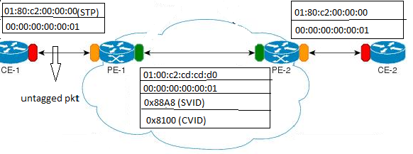
L2CP Tunneling Process in Provider Bridge
Default Behavior
When a control packet arrives at a Provider Edge (PE) router on an Attachment Circuit (AC) port, the system treats it as standard customer traffic.
• Encapsulation: The PE router takes the incoming control frame (tagged or untagged) and encapsulates it directly with MPLS labels (the Transport label and the Service/VC label).
• Transport: The packet is switched across the MPLS core like any other data packet. The provider's core routers (P-routers) do not "see" the control MAC addresses because they are hidden behind MPLS headers.
• Decapsulation: The remote PE router strips the MPLS labels and forwards the original L2CP frame to the destination CE.
The LACP Exception: By default, LACP frames are often consumed (peered) by the PE to manage the local link aggregation between the CE and PE. All other L2CP protocols are typically tunneled by default.
L2CP Behavior
Default L2CP decision in provider bridging case:
Protocol Type | L2CP destination address | Ethertype/subtype | Default L2CP action |
|---|---|---|---|
STP (Spanning Tree Protocols) | 01-80-c2-00-00-00 | N/A | PEER |
LACP (Link Aggregation Control Protocol) | 01-80-c2-00-00-02 | ethertype 0x8809 and subtype 0x1 or 0x2 | PEER |
DOT1X (Port Authentication (802.1 X)) | 01-80-c2-00-00-03 | N/A | PEER |
LLDP (Link layer discovery protocol) | 01-80-c2-00-00-0e | ethertype 0x88CC | PEER |
EFM (Ethernet first mile (Link OAM)) | 01-80-c2-00-00-02 | ethertype 0x8809 and subtype 0x3 | PEER |
ELMI (Ethernet Local Management Interface) | 01-80-c2-00-00-07 | ethertype 0x88EE | PEER |
L2CP Configuration in Provider Bridging
Enabling tunneling at interface:
(config)#bridge 1 protocol provider-rstp edge
(config)#vlan database
(config-vlan)#vlan 2-10 bridge 1 state enable
(config-vlan)#vlan 11 type service point-point bridge 1 state enable
(config-vlan)#ex
(config)#cvlan registration table map1 bridge 1
(config-cvlan-registration)#cvlan 2 svlan 11
(config-cvlan-registration)#ex
(config)#interface xe1
(config-if)#switchport
(config-if)#bridge-group 1
(config-if)#switchport mode customer-edge hybrid
(config-if)#switchport customer-edge hybrid allowed vlan all
(config-if)#switchport customer-edge vlan registration map1
(config-if)#l2protocol stp tunnel
#show running-config interface xe1
!
interface xe1
speed 1g
switchport
bridge-group 1
switchport mode customer-edge hybrid
switchport customer-edge hybrid allowed vlan all
switchport customer-edge vlan registration map1
l2protocol stp tunnel
customer-spanning-tree provider-edge svlan 11 path-cost 128
(config-if)#commit
Configuring egress interfaces:
(config)#interface xe2
(config-if)#switchport
(config-if)#bridge-group 1
(config-if)#switchport mode provider-network
(config-if)#switchport provider-network allowed vlan all
(config-if)#commit
Validation
To display L2protocol information:
#show l2protocol processing interface xe1
Bridge Interface Name Protocol Processing Status Hardware Status
====== ============== ======== ================= ===============
1 xe1 stp Tunnel Tunnel
1 xe1 lacp Peer Peer
1 xe1 dot1x Peer Peer
1 xe1 lldp Peer Peer
1 xe1 efm Peer Peer
1 xe1 elmi Peer Peer
To display L2protocol counters:
#show l2protocol interface counters
Interface xe1
Tunnel : stp : 45
L2CP Tunneling in L2VPN (VPLS/VPWS/Hybrid)
In L2VPN environments—such as VPLS (Multipoint) or VPWS (Point-to-Point) or Hybrid (Bridge+L2VPN)—L2CP tunneling ensures that Layer 2 control protocols (like STP, LLDP, or CDP) can traverse the MPLS core. This allows geographically separated Customer Edge (CE) devices to behave as if they are on the same local segment.
Default Behavior
A Hybrid Port is a complex interface that handles both local Layer 2 switching (Bridge) and L2VPN (VPLS/VPWS) services simultaneously.
The Switch to Peering: Unlike standard AC ports, when a port is configured as Hybrid, the default behavior for L2CP often shifts to Peering mode. In this mode, the PE router "intercepts" and processes the control frames itself (e.g., the PE participates in the customer's Spanning Tree).
Overriding Behavior: If the goal is to pass these frames through to the remote site instead of processing them locally, you must manually apply L2CP override configurations (such as l2-protocol tunneling commands) to force the hybrid port back into a tunneling state for specific protocols.
The following illustration depicts the L2CP frames tunneling in a L2VPN environment.
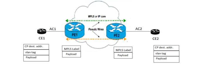
L2CP tunneling in L2VPN
L2CP Behavior
Default L2CP behavior in VPLS/VPWS/Hybrid environments:
VPLS/VPWS
Protocol Type | L2CP destination address | Default L2CP action |
|---|---|---|
STP (Spanning Tree Protocols) | 01-80-c2-00-00-00 | TUNEEL |
LACP (Link Aggregation Control Protocol) | 01-80-c2-00-00-02 | PEER |
DOT1X (Port Authentication (802.1 X)) | 01-80-c2-00-00-03 | TUNNEL |
LLDP (Link layer discovery protocol) | 01-80-c2-00-00-0e | TUNNEL |
EFM (Ethernet first mile (Link OAM)) | 01-80-c2-00-00-02 | TUNNEL |
ELMI (Ethernet Local Management Interface) | 01-80-c2-00-00-07 | TUNNEL |
Hybrid (Bridge+ L2VPN):
Protocol Type | L2CP destination address | Default L2CP action |
|---|---|---|
STP (Spanning Tree Protocols) | 01-80-c2-00-00-00 | PEER |
LACP (Link Aggregation Control Protocol) | 01-80-c2-00-00-02 | PEER |
DOT1X (Port Authentication (802.1 X)) | 01-80-c2-00-00-03 | PEER |
LLDP (Link layer discovery protocol) | 01-80-c2-00-00-0e | PEER |
EFM (Ethernet first mile (Link OAM)) | 01-80-c2-00-00-02 | PEER |
ELMI (Ethernet Local Management Interface) | 01-80-c2-00-00-07 | PEER |
Basic Configuration for L2CP in VPLS
Enabling tunneling at ingress VPLS interface:
#show run in xe12
!
interface xe12
speed 1g
mpls-l2-circuit vc1 service-template svc1
!
#config ter
#(config)interface xe12
(config-if)#commit
Validation
To display L2CP information:
#show l2protocol processing interface xe12
Bridge Interface Name Protocol Processing Status Hardware Status
====== ============== ======== ================= ===============
- xe12 stp Discard Discard
- xe12 lacp None Peer
- xe12 dot1x None Tunnel
- xe12 lldp None Tunnel
- xe12 efm None Tunnel
- xe12 elmi None Tunnel
L2CP Configuration in Hybrid + VPLS
Enabling tunneling at bridged interface:
(config-if)#show run in xe11
!
interface xe11
speed 1g
switchport
bridge-group 1
switchport mode trunk
switchport trunk allowed vlan all
mpls-l2-circuit vc1 service-template svc1
#config ter
#(config)interface xe11
(config-if)#l2protocol stp tunnel
(config-if)#commit
(config-if)#end
Validation
To display L2CP information:
#show l2protocol processing interface xe11
Bridge Interface Name Protocol Processing Status Hardware Status
====== ============== ======== ================= ===============
- xe11 stp Tunnel Tunnel
- xe11 lacp None Peer
- xe11 dot1x None Peer
- xe11 lldp None Peer
- xe11 efm None Peer
- xe11 elmi None Peer
(config)#in xe11
(config-if)#no l2protocol stp
(config-if)#end
#show l2protocol processing interface xe11
Bridge Interface Name Protocol Processing Status Hardware Status
====== ============== ======== ================= ===============
- xe11 stp None Peer
- xe11 lacp None Peer
- xe11 dot1x None Peer
- xe11 lldp None Peer
- xe11 efm None Peer
- xe11 elmi None Peer
Note: If the configuration is not done, hardware status shows the default values while the configured will be none. On configuring L2CP on interface, configured and hardware status will be same.
L2CP Tunneling for EVPN MPLS
EVPN-MPLS utilizes the Border Gateway Protocol (BGP) as a control plane to distribute MAC addresses and reachability information, while using an MPLS data plane for transport. In this architecture, L2CP tunneling is essential for providing a "transparent wire" experience between Customer Edge (CE) devices across a Layer 3 MPLS core.
The following illustration depicts the L2CP frames tunneling in an EVPN MPLS Single Home environment.
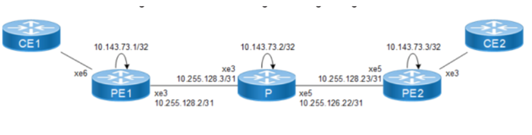
L2CP tunneling in EVPN MPLS SH
Default Behavior
EVPN-MPLS handles L2CP tunneling through a Sub-interface (Sub-ifp) framework. While the actual transport happens over the EVPN instance, the policy—determining which protocols are tunneled—is typically defined at the Parent Interface level (the physical port or LAG connecting the CE).
Because the MPLS core operates at Layer 3, it is naturally unaware of the Ethernet headers or Layer-2 control protocols, ensuring strict separation between the provider network and customer Layer-2 domains. This separation ensures that the provider's core routers (P-routers) are never burdened by customer’s network changes.
L2CP tunneling in EVPN-MPLS enables L2CP frames to be transparently transported between CE devices across both single-homed and multi-homed Ethernet segments. L2CP frames are identified at the ingress PE based on well-known destination MAC addresses, Ethertype values, and configured service policies, which determine whether the frames are tunneled, locally processed, or discarded.
L2CP Behavior
When an L2CP frame is tunneled, the ingress PE suppresses local protocol processing and encapsulates the complete Ethernet frame into EVPN and MPLS headers before forwarding it across the MPLS core. The frame is treated as a standard data packet. Core routers perform label switching only and remain unaware of the control protocol semantics. At the egress PE removes the EVPN and MPLS encapsulation and delivers the original L2CP frame unchanged to the destination CE device. This mechanism preserves end-to-end Layer-2 control plane behavior for customer networks while maintaining isolation and scalability within the EVPN-MPLS provider infrastructure.
• Tunnel - Transparently tunnels the L2 control plane BPDU such as Dot1x, EFM, ELMI,LLDP, xSTP, LACP across EVPN-MPLS networks based on configured egress tunnels.
• Peer - Uplifts the L2 control packet to the CPU/control plane for processing.
• Discard - Drops the L2 control packers .
Default behavior is Peer.
One of the unique strengths of EVPN-MPLS is Multi-homing (All-Active or Single-Active). When L2CP frames are tunneled in a multi-homed environment, the EVPN control plane ensures that frames like STP BPDUs are handled correctly to avoid loops, often using Ethernet Segment Identifiers (ESI) to manage split-horizon forwarding.
The following illustration depicts the L2CP frames tunneling in an EVPN MPLS Multi Home environment.
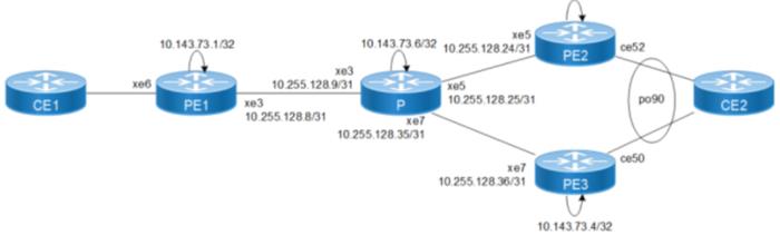
L2CP tunneling for EVPN MPLS MH
Basic Configuration for L2CP in EVPN MPLS
(config)#in xe6 | Entering into interface level of access side interface |
(config-if)#l2protocol <protocol> tunnel | Enabling tunnel for the L2CP protocol |
(config-if)#l2protocol <protocol> peer | Enabling peer for the L2CP protocol |
(config-if)#l2protocol <protocol> discard | Enabling discard for the L2CP protocol |
Validation
PE1#show l2protocol processing interface <interface>
Bridge Interface Name Protocol Processing Status Hardware Status
====== ============== ======== ================= ===============
- xe6 stp Tunnel Peer
- xe6 lacp Tunnel Peer
- xe6 dot1x Peer Peer
- xe6 lldp Peer Peer
- xe6 efm Discard Discard
- xe6 elmi Discard Discard
- xe6 synce Discard Discard
PE1#show l2protocol interface po90 counters
Interface po90
Peer : lacp : 94
Peer : stp : 298
Peer : elmi : 172
Peer : dot1x : 172
Discard : stp : 6558
Discard : elmi : 8326
Discard : dot1x : 9839
Tunnel counters won't get incremented as per design.
PE1#show interface counters queue-stats
E - Egress, I - Ingress, Q-Size is in bytes
* indicates monitor is active
+-------------+--------------------+--------+-----------------+-------------------+-----------------+-------------------+
| Interface | Queue/Class-map | Q-Size | Tx pkts | Tx bytes | Dropped pkts | Dropped bytes |
+-------------+--------------------+--------+-----------------+-------------------+-----------------+-------------------+
cpu reserved-mc (E) 2097152 6 522 0 0
cpu bgp (E) 1048576 2 145 0 0
cpu rsvp-ldp (E) 1048576 7 1060 0 0
cpu bpdu (E) 1048576 6481 4830520 0 0
ge6 q0 (E) 1253376 350 258691 0 0
ge6 q6 (E) 1253376 114 10338 0 0
ge7 q0 (E) 1253376 6 2708 0 0
ge7 q6 (E) 1253376 2 186 0 0
ge8 q0 (E) 1253376 5177 3859861 0 0
xe12 q6 (E) 12517376 6 517 0 0
xe15 q0 (E) 12517376 2 1281 0 0
xe16 q0 (E) 12517376 2253 1694682 0 0
L2CP Tunneling in VXLAN
L2CP tunneling provides support for tunneling control plane frames across VxLAN/MH.
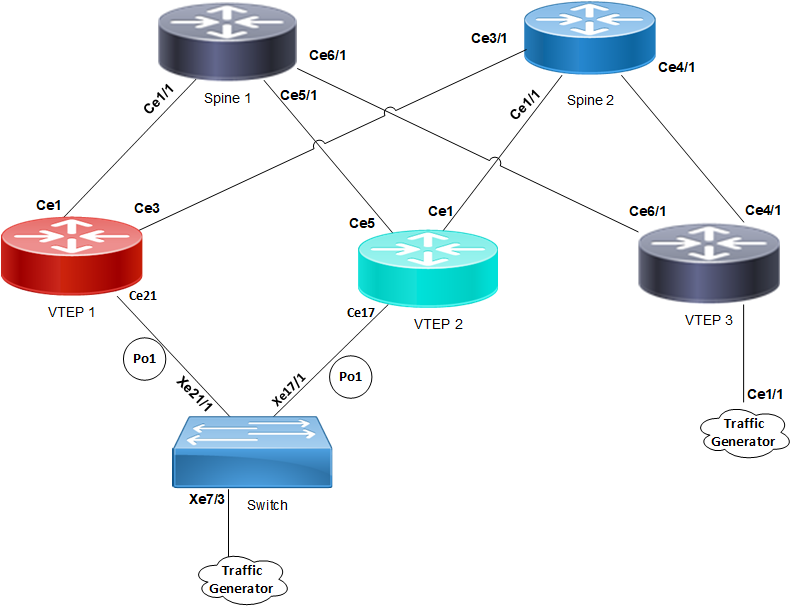
L2CP tunneling in VXLAN
VxLAN creates LAN segments using a MAC in IP encapsulation. The encapsulation carries the original L2 frame received from a host to the destination in another server using IP tunnels. The endpoints of the virtualized tunnel formed using VxLAN are called VTEPs (VXLAN Tunnel EndPoints).
L2CP tunneling provides support for tunneling control plane frames across VxLAN with MH/SH combination.
Any L2CP frame that is destined towards other end with a multicast destination MAC Address for L2 protocol is decided by looking at the frame and upon the configured values of the L2CP service attributes.
As and when control packets with default destination MAC address for any L2 protocol is generated, it will be forwarded by VTEPs that are part of MH towards the VTEP that is part of SH and vice versa.
During this operation, the default destination MAC address for any L2 protocol is replaced with predefined multicast address as destination for tunneling the packets across spine nodes. When tunneled control packet with pre-defined multicast address received on ingress port on the other end of the VTEP, the multicast address is replaced with corresponding control packet multicast address.
L2CP Tunneling Actions in Different Networks
Environment | Primary Transport Method | Ingress Action (Transformation) | Egress Action (Restoration) | Default L2CP Behavior | Key Identification |
|---|---|---|---|---|---|
Provider Bridging (802.1ad / QinQ) | MAC Rewrite + S-Tag | Replaces DMAC with Tunnel MAC (e.g., 01-00-C2-CD-CD-D0) and adds S-VLAN tag. | Restores original Control DMAC and removes S-VLAN tag. | Discard/Peer (Depends on vendor) | Multicast DMAC & C-VLAN |
L2VPN (VPLS / VPWS) | MPLS Label Stack | Encapsulates the entire L2 frame into MPLS Service/Transport labels. | Strips MPLS labels to reveal the original Ethernet frame. | Tunnel (Except LACP) | AC Port Association |
EVPN-MPLS | BGP Control Plane + MPLS Data Plane | Encapsulates frame into EVPN/MPLS headers; suppresses local CPU processing. | Strips EVPN/MPLS labels and forwards original frame to CE. | Peer | Parent Interface Policy / DMAC |
Hybrid Port (Bridge+L2VPN) | Mixed Switching Logic | Context-dependent; can act as a local Bridge (Peer) or a Pipe (Tunnel). | Depends on whether the frame was switched locally or tunneled. | Peer | Sub-interface Config |