Layer 2 Control Protocols Tunneling
Overview
The Layer 2 Control Protocols (L2CP) processing specified here is based largely on the IEEE 802.1Q specification for handling L2CP Frames, i.e. if they should be forwarded, peered, or discarded.
IEEE 802.1Q provides a mechanism for separating the Layer2 control plane into multiple customer and provider control planes. It allows a certain layer 2 control protocol to operate only within a provider network, or to allow interaction between the customer and the provider network, or to pass transparently through a provider network with complete isolation from other customer networks.
In case of non-PB case, packet is forwarded without changing any MAC.
L2CP Tunneling for Provider Bridging
L2CP tunneling provides support for tunneling control plane frames between CE nodes.
In the context of PB, a L2CP frame is defined as any frame containing a destination MAC address as 01:00:0C:CD:CD:D0 or 01:04:DF:CD:CD:D0 (which can be changed via CLI)
When control frames received at CEP port of a PE bridge, predefined multicast address (01-00-C2-CD-CD-D0) is replaced as destination for tunneling the packets across service provider network. If control packets are customer vlan tagged or untagged, then PE bridge will append corresponding service vlan tag to the control packet as per registration table / vlan translation table mapped to the port and send it across the service provider as a data packet.
When tunneled control packet with multicast address (01-00-C2-CD-CD-D0) received on PNP port, the multicast address is replaced with corresponding control packet multicast address and cvlan/svlan removal or update is done as per registration table / vlan translation table.

L2CP tunneling for provider bridging
L2CP Tunneling for VPLS/VPWS/Hybrid (Bridge+VPWS)
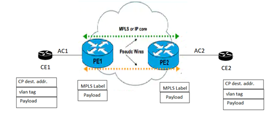
L2CP tunneling provides support for tunneling Control plane frames across L2VPN.
L2CP Tunneling for VXLAN
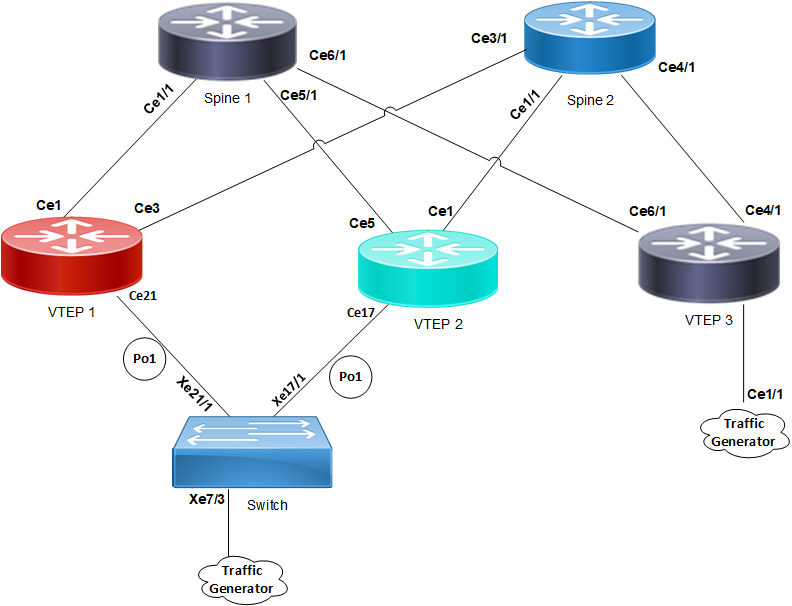
L2CP tunneling provides support for tunneling Control plane frames across VxLAN/MH.
Topology

L2CP tunneling for VXLAN
VXLAN creates LAN segments using a MAC in IP encapsulation. The encapsulation carries the original L2 frame received from a host to the destination in another server using IP tunnels. The endpoints of the virtualized tunnel formed using VXLAN are called VTEPs (VXLAN Tunnel EndPoints).
L2CP tunneling provides support for tunneling control plane frames across VXLAN with MH/SH combination.
Any L2CP frame that is destined towards other end with a multicast destination MAC Address for L2 protocol is decided by looking at the frame and upon the configured values of the L2CP Service Attributes.
As and when Control packets with default destination MAC address for any L2 protocol is generated, it will be forwarded by VTEPs that are part of MH towards the VTEP that is part of SH and vice versa.
During this operation, the default destination MAC address for any L2 protocol is replaced with predefined multicast address as destination for tunneling the packets across SPINE nodes. When tunneled control packet with pre-defined multicast address received on ingress port on the other end of the VTEP, the multicast address is replaced with corresponding control packet multicast address.
Default Behavior
If control packets are received at the PE router on AC port (vlan tagged/untagged), corresponding AC port properties will take care of forwarding to peer PE node. These packets are encapsulated with MPLS headers and sent across the network to the remote PE router. The egress PE router receives the packet and performs MPLS decapsulation and forwards to the CE. Except for LACP, all other control packets are tunnels across the MPLS circuit.

L2CP tunneling for VPLS/VPWS/Hybrid (bridge+VPWS)
Hybrid Port
When the incoming port is configured as Hybrid (Bridge+L2VPN), L2CP switches to peering mode. You can override this behavior with the help of L2CP configurations.
L2CP Behavior
The action taken for a given L2CP Frame at a given L2CP Decision Point depends upon the Destination Address within the frame, and upon the configured values of the L2CP Service Attributes.
The three possible actions at an L2CP Decision Points are: Discard, Peer, or Pass/Tunnel.
Discard | The L2CP frame is neither peered nor forwarded. |
Peer | The L2CP frame will be processed. |
Pass/Tunnel | Pass (or forwarded) means that the frame will be passed transparently in the same way as normal data frames. |
Default L2CP configuration
Default L2CP decision in Provider Bridging case:
Protocol Type | L2CP destination address | Ethertype/subtype | Default L2CP action |
|---|---|---|---|
STP (Spanning Tree Protocols) | 01-80-c2-00-00-00 | N/A | PEER |
LACP (Link Aggregation Control Protocol) | 01-80-c2-00-00-02 | ethertype 0x8809 and subtype 0x1 or 0x2 | PEER |
DOT1X (Port Authentication (802.1 X)) | 01-80-c2-00-00-03 | N/A | PEER |
LLDP (Link layer discovery protocol) | 01-80-c2-00-00-0e | ethertype 0x88CC | PEER |
EFM (Ethernet first mile (Link OAM)) | 01-80-c2-00-00-02 | ethertype 0x8809 and subtype 0x3 | PEER |
ELMI (Ethernet Local Management Interface) | 01-80-c2-00-00-07 | ethertype 0x88EE | PEER |
Default L2CP Decision in VPLS/VPWS/Hybrid case:
• For bridged packets in case of hybrid port:
Protocol Type | L2CP destination address | Default L2CP action |
|---|---|---|
STP(Spanning Tree Protocols) | 01-80-c2-00-00-00 | PEER |
LACP (Link Aggregation Control Protocol) | 01-80-c2-00-00-02 | PEER |
DOT1X (Port Authentication (802.1 X)) | 01-80-c2-00-00-03 | PEER |
LLDP (Link layer discovery protocol) | 01-80-c2-00-00-0e | PEER |
EFM (Ethernet first mile (Link OAM)) | 01-80-c2-00-00-02 | PEER |
ELMI (Ethernet Local Management Interface) | 01-80-c2-00-00-07 | PEER |
• For VPLS/VPWS:
Protocol Type | L2CP destination address | Default L2CP action |
|---|---|---|
STP(Spanning Tree Protocols) | 01-80-c2-00-00-00 | TUNEEL |
LACP (Link Aggregation Control Protocol) | 01-80-c2-00-00-02 | PEER |
DOT1X (Port Authentication (802.1 X)) | 01-80-c2-00-00-03 | TUNNEL |
LLDP (Link layer discovery protocol) | 01-80-c2-00-00-0e | TUNNEL |
EFM (Ethernet first mile (Link OAM)) | 01-80-c2-00-00-02 | TUNNEL |
ELMI (Ethernet Local Management Interface) | 01-80-c2-00-00-07 | TUNNEL |
Operational Concepts and Scenarios
Basic Configuration for L2CP for Hybrid+VPLS
Enabling tunneling at bridged interface:
(config-if)#show run in xe11
!
interface xe11
speed 1g
switchport
bridge-group 1
switchport mode trunk
switchport trunk allowed vlan all
mpls-l2-circuit vc1 service-template svc1
#config ter
#(config)interface xe11
(config-if)# l2protocol stp tunnel
(config-if)#commit
(config-if)#end
To display L2CP information:
#show l2protocol processing interface xe11
Bridge Interface Name Protocol Processing Status Hardware Status
====== ============== ======== ================= ===============
- xe11 stp Tunnel Tunnel
- xe11 lacp None Peer
- xe11 dot1x None Peer
- xe11 lldp None Peer
- xe11 efm None Peer
- xe11 elmi None Peer
(config)#in xe11
(config-if)#no l2protocol stp
(config-if)#end
#show l2protocol processing interface xe11
Bridge Interface Name Protocol Processing Status Hardware Status
====== ============== ======== ================= ===============
- xe11 stp None Peer
- xe11 lacp None Peer
- xe11 dot1x None Peer
- xe11 lldp None Peer
- xe11 efm None Peer
- xe11 elmi None Peer
Note: If the configuration is not done, hardware status shows the default values while the configured will be none. On configuring L2CP on interface, configured and hardware status will be same.
Basic Configuration for L2CP in VPLS
Enabling tunneling at ingress VPLS interface:
#show run in xe12
!
interface xe12
speed 1g
mpls-l2-circuit vc1 service-template svc1
!
#config ter
#(config)interface xe12
(config-if)#commit
To display L2CP information:
#show l2protocol processing interface xe12
Bridge Interface Name Protocol Processing Status Hardware Status
====== ============== ======== ================= ===============
- xe12 stp Discard Discard
- xe12 lacp None Peer
- xe12 dot1x None Tunnel
- xe12 lldp None Tunnel
- xe12 efm None Tunnel
- xe12 elmi None Tunnel
Basic Configuration for L2CP on Provider Bridging
Enabling tunneling at interface:
(config)#bridge 1 protocol provider-rstp edge
(config)#vlan database
(config-vlan)#vlan 2-10 bridge 1 state enable
(config-vlan)#vlan 11 type service point-point bridge 1 state enable
(config-vlan)#ex
(config)#cvlan registration table map1 bridge 1
(config-cvlan-registration)#cvlan 2 svlan 11
(config-cvlan-registration)#ex
(config)#interface xe1
(config-if)#switchport
(config-if)#bridge-group 1
(config-if)#switchport mode customer-edge hybrid
(config-if)#switchport customer-edge hybrid allowed vlan all
(config-if)#switchport customer-edge vlan registration map1
(config-if)#l2protocol stp tunnel
#show running-config interface xe1
!
interface xe1
speed 1g
switchport
bridge-group 1
switchport mode customer-edge hybrid
switchport customer-edge hybrid allowed vlan all
switchport customer-edge vlan registration map1
l2protocol stp tunnel
customer-spanning-tree provider-edge svlan 11 path-cost 128
(config-if)#commit
Configuring egress interfaces”
(config)#interface xe2
(config-if)#switchport
(config-if)#bridge-group 1
(config-if)#switchport mode provider-network
(config-if)#switchport provider-network allowed vlan all
(config-if)#commit
To display L2protocol information:
#show l2protocol processing interface xe1
Bridge Interface Name Protocol Processing Status Hardware Status
====== ============== ======== ================= ===============
1 xe1 stp Tunnel Tunnel
1 xe1 lacp Peer Peer
1 xe1 dot1x Peer Peer
1 xe1 lldp Peer Peer
1 xe1 efm Peer Peer
1 xe1 elmi Peer Peer
To display L2protocol counters:
#show l2protocol interface counters
Interface xe1
Tunnel : stp : 45