Virtual Private Wire Service Configuration
This chapter shows configurations for Virtual Private Wire Service (VPWS), where a point-to-point Layer 2 VPN service interconnects multiple Ethernet LANs across an MPLS backbone.
Overview
An MPLS Layer 2 Virtual Circuit (VC) is a point-to-point Layer 2 connection transported via MPLS on the service provider’s network. The Layer 2 circuit is transported over a single Label Switched Path (LSP) tunnel between two Provider Edge (PE) routers.
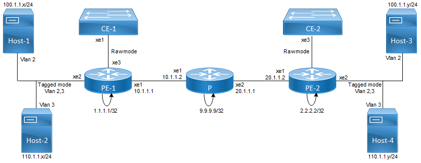
The following diagram illustrates the configuration steps in this section. In this sample, the VC host devices, Host1 and Host2, are connected to the Provider Edge (PE) router PE-1; and Host3 and Host4 are connected to PE-2. The VC is established between PE-1 and PE-2. Interface xe2, on PE-1 and PE-2, is connected to the customer network; xe1, on PE-1 and PE-2, is connected to the MPLS cloud.
MPLS Layer 2 Virtual Circuit
The VC configuration process can be divided into the following steps:
Note: Loopback addresses being used should be advertised through OSPF, or should be statically routed.
1. Configure the IP address and OSPF for the PE-1, P (Provider), and PE-2 routers.
2. Configure MPLS and LDP on PE-1, P, and PE-2, and LDP targeted peer for the PE-1 and PE-2 routers. (If RSVP is used for configuring trunks, LDP must be configured on PE-1 and PE-2, and RSVP must be configured on PE-1, P, and PE-2.)
3. Configure the VC.
4. Bind the customer interface to the VC.
Configure IP Address and OSPF on Routers
Configure the IP addresses and OSPF on the PE-1, P, and PE-2 routers.
PE-1
#configure terminal | Enter configure mode. |
(config)#interface lo | Specify the loopback interface (lo0) to be configured. |
(config-if)#ip address 1.1.1.1/32 secondary | Set the IP address of the loopback interface to 1.1.1.1/32. |
(config-if)#exit | Exit interface mode. |
(config)#interface xe1 | Specify the interface (xe1) to be configured. |
(config-if)#ip address 10.1.1.1/24 | Set the IP address of the interface to 10.1.1.1/24. |
(config-if)#exit | Exit interface mode. |
(config)#router ospf 100 | Configure the routing process and specify the Process ID (100). The Process ID should be a unique positive integer identifying the routing process. |
(config-router)#network 10.1.1.0/24 area 0 (config-router)#network 1.1.1.1/32 area 0 | Define the interface on which OSPF runs and associate the area ID (0) with the interface. |
(config-router)#commit | Commit the transaction. |
P
#configure terminal | Enter configure mode. |
(config)#interface lo | Specify the loopback interface (lo0) to be configured. |
(config-if)#ip address 9.9.9.9/32 secondary | Set the IP address of the loopback interface to 9.9.9.9/32. |
(config-if)#exit | Exit interface mode. |
(config)#interface xe1 | Specify the interface (xe1) to be configured. |
(config-if)#ip address 10.1.1.2/24 | Set the IP address of the interface to 10.1.1.2/24. |
(config-if)#exit | Exit interface mode. |
(config)#interface xe2 | Specify the interface (xe2) to be configured. |
(config-if)#ip address 20.1.1.1/24 | Set the IP address of the interface to 20.1.1.1/24. |
(config-if)#exit | Exit interface mode. |
(config)#router ospf 100 | Configure the routing process and specify the Process ID (100). The Process ID should be a unique positive integer identifying the routing process. |
(config-router)#network 10.1.1.0/24 area 0 (config-router)#network 20.1.1.0/24 area 0 (config-router)#network 9.9.9.9/32 area 0 | Define the interface on which OSPF runs and associate the area ID (0) with the interface. |
(config-router)#commit | Commit the transaction. |
PE-2
#configure terminal | Enter configure mode. |
(config)#interface lo | Specify the loopback interface (lo0) to be configured. |
(config-if)#ip address 2.2.2.2/32 secondary | Set the IP address of the loopback interface to 2.2.2.2/32. |
(config-if)#exit | Exit interface mode. |
(config)#interface xe1 | Specify the interface (xe1) to be configured. |
(config-if)#ip address 20.1.1.2/24 | Set the IP address of the interface to 20.1.1.2/24. |
(config-if)#exit | Exit interface mode. |
(config)#router ospf 100 | Configure the routing process and specify the Process ID (100). The Process ID should be a unique positive integer identifying the routing process. |
(config-router)#network 20.1.1.0/24 area 0 (config-router)#network 2.2.2.2/32 area 0 | Define the interface on which OSPF runs, and associate the area ID (0) with the interface. |
(config-router)#commit | Commit the transaction. |
Configure MPLS, LDP, and LDP Targeted Peer on Routers
Configure MPLS and LDP on PE-1, P, and PE-2, and LDP targeted peers on PE-1 and PE-2.
Note: If RSVP is used for configuring trunks, LDP must be configured on PE-1 and PE-2, and RSVP must be configured on PE-1, P, and PE-2,
PE-1
#configure terminal | Enter configure mode. |
(config)#router ldp | Enter the Router mode. |
(config)#router-id 1.1.1.1 | Set the router ID to IP address 1.1.1.1 |
(config-router)#transport-address ipv4 1.1.1.1 | Configure the transport address to be used for a TCP session over which LDP will run on an IPv4 interface. |
(config-router)#targeted-peer ipv4 2.2.2.2 | Specify the targeted LDP peer on PE-1. |
(config-router-targeted-peer)# exit | Exit the Router targeted peer mode. |
(config-router)#exit | Exit the Router mode. |
(config)#interface xe1 | Specify the interface (xe1) to be configured. |
(config-if)#label-switching | Enable label switching on interface xe1. |
(config-if)#enable-ldp ipv4 | Enable LDP on interface xe1.. |
(config-if)#commit | Commit the transaction. |
P
#configure terminal | Enter configure mode. |
(config)#router ldp | Enter the Router mode. |
(config)#router-id 9.9.9.9 | Set the router ID to IP address 9.9.9.9 |
(config-router)#transport-address ipv4 9.9.9.9 | Configure the transport address to be used for a TCP session over which LDP will run on an IPv4 interface. |
(config-router)#exit | Exit the Router mode. |
(config)#interface xe1 | Specify the interface (xe1) to be configured. |
(config-if)#label-switching | Enable label switching on interface xe2. |
(config-if)#enable-ldp ipv4 | Enable LDP on interface xe2. |
(config-if)#exit | Exit interface mode. |
(config)#interface xe2 | Specify the interface (xe2) to be configured. |
(config-if)#label-switching | Enable label switching on interface xe2. |
(config-if)#enable-ldp ipv4 | Enable LDP on interface xe2. |
(config-if)#commit | Commit the transaction. |
PE-2
#configure terminal | Enter configure mode. |
(config)#router ldp | Enter the Router mode. |
(config)#router-id 2.2.2.2 | Set the router ID to IP address 2.2.2.2 |
(config-router)#transport-address ipv4 2.2.2.2 | Configure the transport address to be used for a TCP session over which LDP will run on an IPv4 interface. |
(config-router)#targeted-peer ipv4 1.1.1.1 | Specify the targeted LDP peer on PE-2. |
(config-router-targeted-peer)# exit | Exit the Router targeted peer mode. |
(config-router)#exit | Exit the Router mode. |
(config)#interface xe1 | Specify the interface(xe1) to be configured. |
(config-if)#label-switching | Enable label switching on interface xe1. |
(config-if)#enable-ldp ipv4 | Enable LDP on interface xe1. |
(config-if)#commit | Commit the transaction. |
Configure VC
Configure the VC. Each VC ID uniquely identifies the Layer-2 circuit among all the Layer-2 circuits.
Note: Both PE routers (endpoints) must be configured with the same VC-ID (100 in this example).
PE-1
#configure terminal | Enter configure mode. |
(config)#mpls l2-circuit t1 100 2.2.2.2 | Configure the VC for PE-2. In this example, t1 is the VC name, 100 is the VC ID, and 2.2.2.2 is the VC endpoint IP address. |
(config)#commit | Save transaction into the database |
PE-2
#configure terminal | Enter configure mode. |
(config)#mpls l2-circuit t1 100 1.1.1.1 | Configure the VC for PE-1. In this example, t1 is the VC name, 100 is the VC ID, and 1.1.1.1 is the VC endpoint IP address. |
(config)#commit | Commit the transaction. |
Bind Customer Interface to VC
Bind the customer interface to the VC using one of the two procedures described below: Layer-2 untagged traffic or Layer-2 tagged traffic.
Note: Layer 2 VCs can only be bound to Layer 2 interfaces. The VC encapsulation method should be Ethernet (default), VLAN.
Layer 2 Untagged Traffic
Use Access mode for Layer 2 untagged traffic.
PE-1
#configure terminal | Enter configure mode. |
(config)#service-template SUT1 | Create a service template SUT1 |
(config-svc)#match untagged | Allow untagged traffic. |
(config-svc)#exit | Exit the service template mode |
(config)#interface xe3 | Specify the interface (xe3) to be configured. |
(config-if)#switchport | Switch to Layer-2 mode. |
(config-if)#mpls-l2-circuit t1 service-template SUT1 | Bind the interface to the VC with service template. |
(config-if)#commit | Commit the transaction. |
PE-2
#configure terminal | Enter configure mode. |
(config)#service-template SUT1 | Create a service template SUT1 |
(config-svc)#match untagged | Allow untagged traffic. |
(config-svc)#exit | Exit the service template mode |
(config)#interface xe3 | Specify the interface (xe3) to be configured. |
(config-if)#switchport | Switch to Layer-2 mode. |
(config-if)#mpls-l2-circuit t1 service-template SUT1 | Bind the interface to the VC with service template. |
(config-if)#commit | Commit the transaction. |
Layer 2 Tagged Traffic
Use Trunk mode for Layer-2 tagged traffic. The following configuration allows only VLAN 2 and 3 traffic.
PE-1
#configure terminal | Enter configure mode. |
(config)#mpls l2-circuit t2 200 2.2.2.2 | Configure the VC for PE-2. In this example, t2 is the VC name, 200 is the VC ID, and 2.2.2.2 is the VC endpoint IP address. |
(config-pseudowire)#exit | Exit pseudowire config mode. |
(config)#service-template ST1 | Create a service template ST1 |
(config-svc)#match outer-vlan 2 | Allow VLAN 2 traffic on this VC. |
(config-svc)#match outer-vlan 3 | Allow VLAN 3 traffic on this VC. |
(config-svc)#exit | Exit the service template mode |
(config)#interface xe2 | Specify the interface (xe2) to be configured. |
(config-if)#switchport | Switch to Layer-2 mode. |
(config-if)#mpls-l2-circuit t2 service-template ST1 | Bind the interface to the VC with service template. |
(config-if)#commit | Commit the transaction. |
PE-2
#configure terminal | Enter configure mode. |
(config)#mpls l2-circuit t2 200 1.1.1.1 | Configure the VC for PE-2. In this example, t2 is the VC name, 200 is the VC ID, and 1.1.1.1 is the VC endpoint IP address. |
(config-pseudowire)#exit | Exit pseudowire config mode. |
(config)#service-template ST1 | Create a service template ST1 |
(config-svc)#match outer-vlan 2 | Allow VLAN 2 traffic on this VC. |
(config-svc)#match outer-vlan 3 | Allow VLAN 3 traffic on this VC. |
(config-svc)#exit | Exit the service template mode |
(config)#interface xe2 | Specify the interface (xe2) to be configured. |
(config-if)#switchport | Switch to Layer-2 mode. |
(config-if)#mpls-l2-circuit t2 service-template ST1 | Bind the interface to the VC with service template. |
(config-if)#commit | Commit the transaction. |
Validation
Use the show ldp mpls-l2-circuit (Control Plane) command, and the show mpls vc-table (Forwarding Plane) command, to display complete information about the Layer 2 VC.
If the VC State is UP in the output from the show ldp mpls-l2 circuit command, and the Status is Active in the output of the show mpls vc-table command, a ping from CE1 to CE2 should be successful.
#show ldp mpls-l2-circuit
Transport Client VC Trans Local Remote Destination
VC ID Binding State Type VC Label VC Label Address
100 xe3 UP Ethernet VLAN 26240 26240 2.2.2.2
200 xe2 UP Ethernet VLAN 26241 26241 2.2.2.2
#show mpls vc-table
(m) - Service mapped over multipath transport
(e) - Service mapped over LDP ECMP
VC-ID Vlan-ID Inner-Vlan-ID Access-Intf Network-Intf Out Label Tunnel-Label Nexthop Status
100 N/A N/A xe3 xe1 26240 25600 2.2.2.2 Active
200 N/A N/A xe2 xe1 26241 25600 2.2.2.2 Active
PE2#show ldp mpls-l2-circuit
Transport Client VC VC Local Remote Destination
VC ID Binding State Type VC Label VC Label Address
100 xe3 UP Ethernet VLAN 26240 26240 1.1.1.1
200 xe2 UP Ethernet VLAN 26241 26241 1.1.1.1
PE2#sh mpls vc-table
(m) - Service mapped over multipath transport
(e) - Service mapped over LDP ECMP
VC-ID Vlan-ID Inner-Vlan-ID Access-Intf Network-Intf Out Label Tunnel-Label Nexthop Status
100 N/A N/A xe3 xe1 26240 25601 1.1.1.1 Active 200 N/A N/A xe2 xe1 26241 25601 1.1.1.1 Active
PE1#show ldp mpls-l2-circuit
Transport Client VC VC Local Remote Destination
VC ID Binding State Type VC Label VC Label Address
100 xe3 UP Ethernet VLAN 26240 26240 2.2.2.2
200 xe2 UP Ethernet VLAN 26241 26241 2.2.2.2
PE1#show mpls vc-table
(m) - Service mapped over multipath transport
(e) - Service mapped over LDP ECMP
VC-ID Vlan-ID Inner-Vlan-ID Access-Intf Network-Intf Out Label Tunnel-Label Nexthop Status
100 N/A N/A xe3 xe1 26240 25600 2.2.2.2 Active 200 N/A N/A xe2 xe1 26241 25600 2.2.2.2 Active
PE2#show ldp mpls-l2-circuit
Transport Client VC VC Local Remote Destination
VC ID Binding State Type VC Label VC Label Address
100 xe3 UP Ethernet VLAN 26240 26240 1.1.1.1
200 xe2 UP Ethernet VLAN 26241 26241 1.1.1.1
PE2#show mpls vc-table
(m) - Service mapped over multipath transport
(e) - Service mapped over LDP ECMP
VC-ID Vlan-ID Inner-Vlan-ID Access-Intf Network-Intf Out Label Tunnel-Label Nexthop Status
100 N/A N/A xe3 xe1 26240 25601 1.1.1.1 Active 200 N/A N/A xe2 xe1 26241 25601 1.1.1.1 Active
These additional commands can also be used to display information about the Layer 2 virtual circuits.
show ldp mpls-l2-circuit detail
show ldp mpls-l2-circuit VC-ID
show ldp mpls-l2-circuit VC-ID detail
show mpls l2-circuit
PE1
PE1#show ldp mpls-l2-circuit detail
PW ID: 100, VC state is up
Access IF: xe3,up,AC state is up
Session IF: xe1, state is up
Destination: 2.2.2.2, Peer LDP Ident: 2.2.2.2
Local vctype: vlan, remote vctype :vlan
Local groupid: 0, remote groupid: 0
Local label: 26240, remote label: 26240
Local MTU: 1500, Remote MTU: 1500
Local Control Word: disabled Remote Control Word: Not-Applicable Current use: disabled Local Flow
Label Direction: Disabled, Static: Disabled
Remote Flow Label Direction: Disabled, Static: Disabled
Local PW Status Capability : disabled
Remote PW Status Capability : disabled
Current PW Status TLV : disabled
MPLS VC UpTime : 00:03:19
PW ID: 200, VC state is up
Access IF: xe2,up,AC state is up
Session IF: xe1, state is up
Destination: 2.2.2.2, Peer LDP Ident: 2.2.2.2
Local vctype: vlan, remote vctype :vlan
Local groupid: 0, remote groupid: 0
Local label: 26241, remote label: 26241
Local MTU: 1500, Remote MTU: 1500
Local Control Word: disabled Remote Control Word: Not-Applicable Current use: disabled Local Flow Label Direction: Disabled, Static: Disabled
Remote Flow Label Direction: Disabled, Static: Disabled
Local PW Status Capability : disabled
Remote PW Status Capability : disabled
Current PW Status TLV : disabled
MPLS VC UpTime : 00:01:16
PE1#show ldp mpls-l2-circuit 100
Transport Client VC VC Local Remote Destination
VC ID Binding State Type VC Label VC Label Address
100 xe3 UP Ethernet VLAN 26240 26240 2.2.2.2
PE1#show ldp mpls-l2-circuit 200
Transport Client VC VC Local Remote Destination
VC ID Binding State Type VC Label VC Label Address
200 xe2 UP Ethernet VLAN 26241 26241 2.2.2.2
PE1#show ldp mpls-l2-circuit
100 detail PW ID: 100, VC state is up
Access IF: xe3,up,AC state is up
Session IF: xe1, state is up
Destination: 2.2.2.2, Peer LDP Ident: 2.2.2.2
Local vctype: vlan, remote vctype :vlan
Local groupid: 0, remote groupid: 0
Local label: 26240, remote label: 26240
Local MTU: 1500, Remote MTU: 1500
Local Control Word: disabled Remote Control Word: Not-Applicable Current use: disabled Local Flow Label Direction: Disabled, Static: Disabled
Remote Flow Label Direction: Disabled, Static: Disabled
Local PW Status Capability : disabled
Remote PW Status Capability : disabled
Current PW Status TLV : disabled
MPLS VC UpTime : 00:04:19
PE1#show ldp mpls-l2-circuit 200 detail
PW ID: 200, VC state is up
Access IF: xe2,up,AC state is up
Session IF: xe1, state is up
Destination: 2.2.2.2, Peer LDP Ident: 2.2.2.2
Local vctype: vlan, remote vctype :vlan
Local groupid: 0, remote groupid: 0
Local label: 26241, remote label: 26241
Local MTU: 1500, Remote MTU: 1500
Local Control Word: disabled Remote Control Word: Not-Applicable Current use: disabled Local Flow
Label Direction: Disabled, Static: Disabled
Remote Flow Label Direction: Disabled, Static: Disabled
Local PW Status Capability : disabled
Remote PW Status Capability : disabled
Current PW Status TLV : disabled MPLS VC UpTime : 00:02:24
PE1#show mpls l2-circuit
MPLS Layer-2 Virtual Circuit: t1, id: 100 PW-INDEX: 1 service-tpid: dot1.q
Endpoint: 2.2.2.2
Control Word: 0
Flow Label Status: Disabled, Direction: None, Static: No
MPLS Layer-2 Virtual Circuit Group: none
Bound to interface: xe3
Virtual Circuit Type: Ethernet VLAN
Virtual Circuit is configured as Primary
Virtual Circuit is configured as Active
Virtual Circuit is active
Service-template : SUT1
Match criteria : Untagged
MPLS Layer-2 Virtual Circuit: t2, id: 200 PW-INDEX: 2 service-tpid: dot1.q
Endpoint: 2.2.2.2
Control Word: 0
Flow Label Status: Disabled, Direction: None, Static: No
MPLS Layer-2 Virtual Circuit Group: none
Bound to interface: xe2
Virtual Circuit Type: Ethernet VLAN
Virtual Circuit is configured as Primary
Virtual Circuit is configured as Active
Virtual Circuit is active
Service-template : ST1
Match criteria : 2,3
PE2
PE2#show ldp mpls-l2-circuit detail
PW ID: 100, VC state is up
Access IF: xe3,up,AC state is up
Session IF: xe1, state is up
Destination: 1.1.1.1, Peer LDP Ident: 10.143.73.1
Local vctype: vlan, remote vctype :vlan
Local groupid: 0, remote groupid: 0
Local label: 26240, remote label: 26240
Local MTU: 1500, Remote MTU: 1500
Local Control Word: disabled Remote Control Word: Not-Applicable Current use: disabled Local Flow Label Direction: Disabled, Static: Disabled
Remote Flow Label Direction: Disabled, Static: Disabled
Local PW Status Capability : disabled
Remote PW Status Capability : disabled
Current PW Status TLV : disabled MPLS VC UpTime : 00:07:08
PW ID: 200, VC state is up
Access IF: xe2,up,AC state is up
Session IF: xe1, state is up
Destination: 1.1.1.1, Peer LDP Ident: 10.143.73.1
Local vctype: vlan, remote vctype :vlan
Local groupid: 0, remote groupid: 0
Local label: 26241, remote label: 26241
Local MTU: 1500, Remote MTU: 1500
Local Control Word: disabled Remote Control Word: Not-Applicable Current use: disabled Local Flow Label Direction: Disabled, Static: Disabled
Remote Flow Label Direction: Disabled, Static: Disabled
Local PW Status Capability : disabled
Remote PW Status Capability : disabled
Current PW Status TLV : disabled
MPLS VC UpTime : 00:05:05
PE2#show ldp mpls-l2-circuit 100
Transport Client VC VC Local Remote Destination
VC ID Binding State Type VC Label VC Label Address
100 xe3 UP Ethernet VLAN 26240 26240 1.1.1.1
PE2#show ldp mpls-l2-circuit 200
Transport Client VC VC Local Remote Destination
VC ID Binding State Type VC Label VC Label Address
200 xe2 UP Ethernet VLAN 26241 26241 1.1.1.1
PE2#show ldp mpls-l2-circuit
PW ID: 200, VC state is up
Access IF: xe2,up,AC state is up
Session IF: xe1, state is up
Destination: 1.1.1.1, Peer LDP Ident: 10.143.73.1
Local vctype: vlan, remote vctype :vlan
Local groupid: 0, remote groupid: 0
Local label: 26241, remote label: 26241
Local MTU: 1500, Remote MTU: 1500
Local Control Word: disabled Remote Control Word: Not-Applicable Current use: disabled
Local Flow Label Direction: Disabled, Static: Disabled
Remote Flow Label Direction: Disabled, Static: Disabled
Local PW Status Capability : disabled
Remote PW Status Capability : disabled
Current PW Status TLV : disabled
MPLS VC UpTime : 00:06:00
PE2#show mpls l2-circuit
MPLS Layer-2 Virtual Circuit: t1, id: 100 PW-INDEX: 1 service-tpid: dot1.q
Endpoint: 1.1.1.1
Control Word: 0
Flow Label Status: Disabled, Direction: None, Static: No
MPLS Layer-2 Virtual Circuit Group: none
Bound to interface: xe3
Virtual Circuit Type: Ethernet VLAN
Virtual Circuit is configured as Primary
Virtual Circuit is configured as Active
Virtual Circuit is active
Service-template : SUT1
Match criteria : Untagged
MPLS Layer-2 Virtual Circuit: t2, id: 200 PW-INDEX: 2 service-tpid: dot1.q
Endpoint: 1.1.1.1
Control Word: 0
Flow Label Status: Disabled, Direction: None, Static: No
MPLS Layer-2 Virtual Circuit Group: none
Bound to interface: xe2
Virtual Circuit Type: Ethernet VLAN
Virtual Circuit is configured as Primary
Virtual Circuit is configured as Active
Virtual Circuit is active
Service-template : ST1
Match criteria : 2,3
Configure a Static Layer-2 VC
For a static MPLS Layer 2 VC configuration:
1. Configure the VC with the manual option
2. Configure the VC FIB entry
3. Bind the VC; all steps are in the configurations that follow.
PE-1
#configure terminal | Enter configure mode. |
PE1(config)#mpls l2-circuit t3 300 2.2.2.2 | Configure the VC ID for PE1 |
PE1(config-pseuodwire)#manual-pseudowire | Configure pseudowire manual (no signaling) |
PE1(config-pseudowire)#exit | Exit pseudowire config mode. |
PE1(config)#service-template ST3 | Create a service template ST3 |
PE1(config-svc)#exit | Exit the service template mode |
PE1(config)#interface xe2 | Add an FTN entry; where 1000 is the incoming label, 2000 is the outgoing label, 2.2.2.2 is the endpoint, xe1 is the incoming interface name, and xe2 is outgoing interface name. |
PE1(config)#switchport | config interface as switch port. |
PE1(config-if)#mpls-l2-circuit t3 service-template ST3 | Bind the interface to the VC with service template. |
PE1(config-if)#exit | Exit interface mode |
PE1(config)#mpls l2-circuit-fib-entry 300 1000 2000 2.2.2.2 xe1 xe2 | Configure the VC ID with the manual option (no signaling used). |
PE1(config)#commit | Commit the transaction. |
PE-2
#configure terminal | Enter configure mode. |
PE2(config)#mpls l2-circuit t3 300 1.1.1.1 | Configure the VC ID for PE2 |
PE2(config-pseuodwire)#manual-pseudowire | Configure pseudowire manual (no signaling) |
PE2(config-pseudowire)#exit | Exit pseudowire config mode. |
PE2(config)#service-template ST3 | Create a service template ST3 |
(config-svc)#exit | Exit the service template mode |
PE2(config)#interface xe2 | Add an FTN entry; where 2000 is the incoming label, 1000 is the outgoing label, 1.1.1.1 is the endpoint, xe1 is the incoming interface name, and xe 2 is outgoing interface name. |
PE1(config)#switchport | config interface as switch port. |
PE2(config-if)#mpls-l2-circuit t3 service-template ST3 | Bind the interface to the VC with service template. |
PE2(config-if)#exit | Exit interface mode. |
PE2(config)#mpls l2-circuit-fib-entry 300 2000 1000 1.1.1.1 xe1 xe2 | Configure the VC ID with the manual option (no signaling used). |
PE2(config)#end | Exit configure mode. |
PE2(config)#commit | Commit the transaction. |
Validation
This example shows number of configured VCs and its status.
#show mpls vc-table count
-------------------------------
Num PWs : 3
Active PWs : 3
OAM-only PWs : 0
Inactive PWs : 0
-------------------------------
#show ldp mpls-l2-circuit count
----------------------------------------------
Num Signaled PWs: 3 [UP: 3]
----------------------------------------------
Service Template Configuration
PE-1
#configure terminal | Enter configure mode. |
(config)#mpls l2-circuit vc1 10 2.2.2.2 | Configure the VC |
(config-pseudowire)# service-tpid dot1.ad | Configure Service-TPID as dot1.ad (0x88a8) |
(config-pseudowire)#exit | Exit pseudowire config mode. |
(config)# service-template template1 | Configure the service template. |
(config-svc)# match double-tag outer-vlan 204 inner-vlan 203 | Matching criteria for service template. |
(config-svc)#rewrite ingress pop outgoing-tpid dot1.ad | Action performed for service template. |
(config-svc)#exit | Exit configure SVC mode |
(config)#interface xe2 | Specify the interface (xe2) to be configured. |
(config-if)#switchport | Switch to Layer-2 mode. |
(config-if)#dot1ad ethertype 0x88a8 | Configure interface ethertype as dot1.ad (0x88a8) |
(config-if)#mpls-l2-circuit vc1 service-template template1 | Bind the interface to the VC with service template. |
(config-if)#commit | Commit the transaction. |
(config-if)#end | End of Interface and configurations mode. |
PE-2
#configure terminal | Enter configure mode. |
(config)#mpls l2-circuit vc1 10 1.1.1.1 | Configure the VC. |
(config-pseudowire)#service-tpid dot1.ad | Configure Service-TPID as dot1.ad (0x88a8) |
(config-pseudowire)#exit | Exit pseudowire config mode. |
(config)# service-template template1 | Configure the service template. |
(config-svc)# match double-tag outer-vlan 204 inner-vlan 203 | Matching criteria for service template. |
(config-svc)# rewrite ingress pop outgoing-tpid dot1.ad | Action performed for service template. |
(config-svc)#exit | Exit configure SVC mode |
(config)#interface xe2 | Specify the interface (xe2) to be configured. |
(config-if)#switchport | Switch to Layer-2 mode. |
(config-if)#dot1ad ethertype 0x88a8 | Configure interface ethertype as dot1.ad (0x88a8) |
(config-if)#mpls-l2-circuit vc1 service-template template1 | Bind the interface to the VC with service template. |
(config-if)#commit | Commit the transaction. |
(config-if)#end | End of interface and configurations mode. |
Validation
PE1
PE1#show ldp mpls-l2-circuit detail
PW ID: 10, VC state is up
Access IF: xe2,up,AC state is up
Session IF: xe1, state is up
Destination: 2.2.2.2, Peer LDP Ident: 2.2.2.2
Local vctype: vlan, remote vctype :vlan
Local groupid: 0, remote groupid: 0
Local label: 24322, remote label: 52482
Local MTU: 1500, Remote MTU: 1500
Local Control Word: disabled Remote Control Word: Not-Applicable Current use: disabled
Local PW Status Capability : disabled
Remote PW Status Capability : disabled
Current PW Status TLV : disabled
PE1#show mpls l2-circuit detail
MPLS Layer-2 Virtual Circuit: vc1, id: 10 PW-INDEX: 1 service-tpid: dot1.ad
Endpoint: 2.2.2.2
Control Word: 0
MPLS Layer-2 Virtual Circuit Group: none
Bound to interface: xe2
Virtual Circuit Type: Ethernet VLAN
Virtual Circuit is configured as Primary
Virtual Circuit is configured as Active
Virtual Circuit is active
Service-template : template1
Match criteria : 204/203
Action type : Pop
Outgoing tpid : dot1.ad
PE1#show mpls vc-table
VC-ID Vlan-ID Inner-Vlan-ID Access-Intf Network-Intf Out Label Tunnel-Label Nexthop Status
10 N/A N/A xe2 xe1 52482 52480 2.2.2.2 Active
Service Template with Multiple Match
This is to validate the multiple match criteria support in a service template. When multiple match statements are configured only rewrite push is supported, rewrite translate and pop are not supported.
PE-1
#configure terminal | Enter configure mode. |
(config)#mpls l2-circuit t4 400 2.2.2.2 | Configure the VC for PE-1. In this example, t4 is the VC name, 400 is the VC ID, and 2.2.2.2 is the VC endpoint IP address. |
(config-pseudowire)#exit | Exit pseudowire config mode. |
(config)#service-template template4 | Template configuration |
(config-svc)# match outer-vlan 700 | Allow VLAN 700 traffic on this VC |
(config-svc)# match double-tag outer-vlan 1200 inner-vlan 3200 | Allow double tag match with s+c tags |
(config-svc)# match untagged | Allow untagged traffic |
(config-svc)# rewrite ingress push 300 | Push Action performed for service template |
(config)#interface xe2 | Specify the interface (xe2) to be configured. |
(config-if)#switchport | Switch to Layer-2 mode. |
(config-if)#mpls-l2-circuit t4 service-template template4 | Bind the interface to the VC with service template. |
(config-if)#commit | Commit the transaction. |
PE-2
#configure terminal | Enter configure mode. |
(config)#mpls l2-circuit t4 400 1.1.1.1 | Configure the VC for PE-2. In this example, t4 is the VC name, 400 is the VC ID, and 1.1.1.1 is the VC endpoint IP address. |
(config-pseudowire)#exit | Exit pseudowire config mode. |
(config)#service-template template4 | Template configuration |
(config-svc)# match outer-vlan 700 | Allow VLAN 700 traffic on this VC |
(config-svc)# match double-tag outer-vlan 1200 inner-vlan 3200 | Allow double tag match with s+c tags |
(config-svc)# match untagged | Allow untagged traffic |
(config-svc)# rewrite ingress push 300 | Push Action performed for service template |
(config)#interface xe2 | Specify the interface (xe2) to be configured. |
(config-if)#switchport | Switch to Layer-2 mode. |
(config-if)#mpls-l2-circuit t4 service-template template4 | Bind the interface to the VC with service template. |
(config-if)#commit | Commit the transaction. |
Validation
PE1#show ldp mpls-l2-circuit detail
PW ID: 400, VC state is up
Access IF: xe2,up,AC state is up
Session IF: xe1, state is up
Destination: 2.2.2.2, Peer LDP Ident: 2.2.2.2
Local vctype: vlan, remote vctype :vlan
Local groupid: 0, remote groupid: 0
Local label: 24324, remote label: 52485
Local MTU: 1500, Remote MTU: 1500
Local Control Word: disabled Remote Control Word: Not-Applicable Current use: disabled
Local PW Status Capability : disabled
Remote PW Status Capability : disabled
Current PW Status TLV : disabled
PE1#show mpls l2-circuit detail
MPLS Layer-2 Virtual Circuit: t4, id: 400 PW-INDEX: 4 service-tpid: dot1.q
Endpoint: 2.2.2.2
Control Word: 0
MPLS Layer-2 Virtual Circuit Group: none
Bound to interface: xe2
Virtual Circuit Type: Ethernet VLAN
Virtual Circuit is configured as Primary
Virtual Circuit is configured as Active
Virtual Circuit is active
Service-template : template4
Match criteria : 700
1200/3200
untagged
Action type : Push
Action value : 300
PE1#show mpls vc-table
VC-ID Vlan-ID Inner-Vlan-ID Access-Intf Network-Intf Out Label Tunnel-Label Nexthop Status Ecmp-Group
400 N/A N/A xe2 xe1 24322 24320 2.2.2.2 Active N/A
PE2#show mpls vc-table
VC-ID Vlan-ID Inner-Vlan-ID Access-Intf Network-Intf Out Label Tunnel-Label Nexthop Status Ecmp-Group
400 N/A N/A xe2 xe1 24321 24325 1.1.1.1 Active N/A
VPWS-CFM
The below examples contains of Ethernet Operations and Management (OAM) configurations using the Connectivity Fault Management (CFM) protocol.
Connectivity Fault Management detects, verifies, isolates and notifies connectivity failures on a Virtual Bridged LAN (B- VLAN) based on the protocol standard specified in IEEE 802.1ag 2007. It provides discovery and verification of paths through 802.1 bridges and LANs and is part of the Operation, Administration and Management (OAM) module. CFM is transparent to customer data being transported by a network and is capable of providing maximum fault management.
Prerequisite
Configure basic VPWS configuration as in above section.
1. Configure the IP address and OSPF for the PE-1, P (Provider), and PE-2 routers.
2. Configure MPLS and LDP on PE-1, P, and PE-2, and LDP targeted peer for the PE-1 and PE-2 routers. (If RSVP is used for configuring trunks, LDP must be configured on PE-1 and PE-2, and RSVP must be configured on PE-1, P, and PE-2.)
PE1
PE1#configure terminal | Enter configure mode. |
PE1(config)#ethernet cfm domain-type character-string domain-name MD-05 level 0 mip-creation none | Create cfm domain with type as character string and set mip creation criteria to default. |
PE1(config-ether-cfm)#service ma-type string ma-name CFM-2 | Create ma type as string and configure the ma |
PE1(config-ether-cfm-ma)# vpws vc1 | Configure vpws to associate to the MA |
PE1(config-ether-cfm-ma)# ethernet cfm mep up mpid 115 active true vpws vc1 | Create mep up on vpws. |
PE1(config-ether-cfm-ma-mep)#cc multicast state enable | Enable cc multicast. |
PE1(config-ether-cfm-ma-mep)#exit-ether-ma-mep-mode | Exit CFM MEP configuration mode. |
PE1(config-ether-cfm-ma)#mep crosscheck mpid 1115 | Configure crosscheck to remote MEP. |
PE1(config-ether-cfm-ma)#cc interval 10ms | Enable cc interval for 10 millisecond. |
PE1(config-ether-cfm-ma)#exit-ether-ma-mode | Exit CFM MA configuration mode. |
PE1(config-ether-cfm)#exit | Exit ethernet CFM mode. |
PE1(config)#commit | Commit the configuration |
PE1(config)#exit | Exit the configure terminal mode |
PE2
PE2#configure terminal | Enter configure mode. |
PE2(config)#ethernet cfm domain-type character-string domain-name MD-05 level 0 mip-creation none | Create cfm domain with type as character string and set mip creation criteria to default. |
PE2(config-ether-cfm)#service ma-type string ma-name CFM-2 | Create ma type as string and set mip creation criteria to default. |
PE2(config-ether-cfm-ma)#vpws vc1 | Configure vpws to associate to the MA |
PE2(config-ether-cfm-ma)#ethernet cfm mep down mpid 1115 active true vpws vc1 | Create mep up on vpws. |
PE2(config-ether-cfm-ma-mep)#cc multicast state enable | Enable cc multicast. |
PE2(config-ether-cfm-ma-mep)#exit-ether-ma- mep-mode | Exit CFM MEP configuration mode |
PE2(config-ether-cfm-ma)#mep crosscheck mpid 115 | Configure crosscheck to remote MEP in VLAN 512. |
PE2(config-ether-cfm-ma)#cc interval 10ms | Enable cc interval for 10 millisecond. |
PE2(config-ether-cfm-ma)#exit-ether-ma-mode | Exit CFM MA configuration mode. |
PE2(config-ether-cfm)#exit | Exit ethernet CFM mode. |
PE2(config)#commit | Commit the configuration |
PE2(config)#exit | Exit the configure terminal mode |
Validation
PE1
PE1#show ethernet cfm statistics
Continuity Check Messages
CCM Sent : 4378
CCM Received : 0
Loop Back Messages
LBM Sent : 5
LBR Received(Valid) : 5
LBR Received(Bad msdu) : 0
LBR Received(Out-of-Seq): 0
Link Trace Messages
LTM Sent : 2
LTR Sent : 0
LTR Received(Valid) : 2
LTR Received(unexpected): 0
PE1#show ethernet cfm maintenance-points local mep domain MD-05 ma-name CFM-2
MPID Dir Lvl CC-Stat HW-Status CC-Intvl MAC-Address Def Port MD Name
---------------------------------------------------------------------------
115 Up 0 Enable Installed 100 ms b86a.97db.2eca F xe4 MD-05
PE1#show ethernet cfm maintenance-points remote domain MD-05 ma-name CFM-2
MEPID RMEPID LEVEL Rx CCM RDI PEER-MAC TYPE
----------------------------------------------------------------------
115 1115 0 Yes False f88e.a192.4436 Configured
PE1#show ethernet cfm ma status domain MD-05 ma-name CFM-2
MA NAME STATUS
-------------------------------
CFM-2 Active
PE1#show ethernet cfm maintenance-points remote domain MD-05 ma-name CFM-2
MEPID RMEPID LEVEL Rx CCM RDI PEER-MAC TYPE
----------------------------------------------------------------------
115 1115 0 Yes False f88e.a192.4436 Configured
PE1#ping ethernet mac f88e.a192.4436 unicast source 115 domain MD-05 ma CFM-2
success rate is 100 (5/5)
PE1#traceroute ethernet f88e.a192.4436 mepid 115 domain MD-05 ma CFM-2
MP Mac Hops Relay-action Ingress/Egress Ingress/Egress action
f88e.a192.4436 1 RlyHit Ingress IngOK
PE2
PE2#show ethernet cfm statistics
Continuity Check Messages
CCM Sent : 8841
CCM Received : 0
Loop Back Messages
LBM Sent : 5
LBR Received(Valid) : 5
LBR Received(Bad msdu) : 0
LBR Received(Out-of-Seq): 0
Link Trace Messages
LTM Sent : 1
LTR Sent : 2
LTR Received(Valid) : 1
LTR Received(unexpected): 0
PE2#show ethernet cfm maintenance-points local mep domain MD-05 ma-name CFM-2
MPID Dir Lvl CC-Stat HW-Status CC-Intvl MAC-Address Def Port MD Name
---------------------------------------------------------------------------
1115 Up 0 Enable Installed 100 ms f88e.a192.4436 F xe19 MD-05
PE2#show ethernet cfm maintenance-points remote domain MD-05 ma-name CFM-2
MEPID RMEPID LEVEL Rx CCM RDI PEER-MAC TYPE
----------------------------------------------------------------------
1115 115 0 Yes False b86a.97db.2eca Configured
PE2#show ethernet cfm ma status domain MD-05 ma-name CFM-2
MA NAME STATUS
-------------------------------
CFM-2 Active
PE2#show ethernet cfm maintenance-points remote domain MD-05 ma-name CFM-2
MEPID RMEPID LEVEL Rx CCM RDI PEER-MAC TYPE
----------------------------------------------------------------------
1115 115 0 Yes False b86a.97db.2eca Configured
PE2#ping ethernet mac b86a.97db.2eca unicast source 1115 domain MD-05 ma CFM-2
success rate is 100 (5/5)
PE2#traceroute ethernet b86a.97db.2eca mepid 1115 domain MD-05 ma CFM-2
MP Mac Hops Relay-action Ingress/Egress Ingress/Egress action
b86a.97db.2eca 1 RlyHit Ingress IngOK