Point-to-Point Connections Over MPLS
Overview
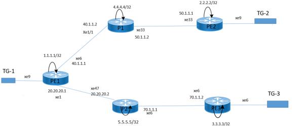
An MPLS Layer 2 Virtual Circuit (VC) facilitates efficient point-to-point Layer 2 connectivity in a service providers MPLS network. It enables Layer 2 circuit transport across the providers infrastructure, ensuring secure communication between remote sites through a single Label Switched Path (LSP) tunnel connecting Provider Edge (PE) routers. This feature optimizes network performance and supports diverse applications and services.
Topology
The VC configuration process can be divided into the following steps:
Note: Loopback addresses being used should be advertised through OSPF, or must be statically routed.
1. Configure the IP address and OSPF for the PE-1, P (Provider), and PE-2 routers.
2. Configure MPLS and LDP on PE-1, P, and PE-2, and LDP targeted peer for the PE-1 and PE-2 routers. (If RSVP is used for configuring trunks, LDP must be configured on PE-1 and PE-2, and RSVP must be configured on PE-1, P, and PE-2.)
3. Configure the VC.
4. Bind the customer interface to the VC.
Configure IP Address and OSPF on Routers
Configure the IP addresses and OSPF on the PE-1, P1,P2, PE2 and PE-3 routers.
PE-1
#configure terminal | Enter configure mode. |
(config)#interface lo | Specify the loopback interface (lo0) to be configured. |
(config-if)#ip address 1.1.1.1/32 secondary | Set the IP address of the loopback interface to 1.1.1.1/ 32. |
(config-if)#exit | Exit interface mode. |
(config)#interface xe6 | Specify the interface (xe6) to be configured. |
(config-if)#ip address 40.1.1.1/24 | Set the IP address of the interface to 40.1.1.1/24 |
(config)#interface xe1 | Specify the interface (xe1) to be configured. |
(config-if)#ip address 20.20.20.1/24 | Set the IP address of the interface to 20.20.20.1/24 |
(config-if)#exit | Exit interface mode. |
(config)#router ospf 100 | Configure the routing process and specify the Process ID (100). The Process ID should be a unique positive integer identifying the routing process. |
(config-router)#network 40.1.1.0/24 area 0 (config-router)#network 1.1.1.1/32 area 0 (config-router)# network 20.20.20.0/24 area 0 | Define the interface on which OSPF runs and associate the area ID (0) with the interface. |
P1
#configure terminal | Enter configure mode. |
(config)#interface lo | Specify the loopback interface (lo0) to be configured. |
(config-if)#ip address 4.4.4.4/32 secondary | Set the IP address of the loopback interface to 9.9.9.9/ 32. |
(config-if)#exit | Exit interface mode. |
(config)#interface xe1/1 | Specify the interface (xe1/1) to be configured. |
(config-if)#ip address 40.1.1.2/24 | Set the IP address of the interface to 40.1.1.2/24. |
(config-if)#exit | Exit interface mode. |
(config)#interface xe33 | Specify the interface (xe33) to be configured. |
(config-if)#ip address 50.1.1.2/24 | Set the IP address of the interface to 50.1.1.1/24. |
(config-if)#exit | Exit interface mode. |
(config)#router ospf 100 | Configure the routing process and specify the Process ID (100). The Process ID should be a unique positive integer identifying the routing process. |
(config-router)#network 40.1.1.0/24 area 0 (config-router)#network 50.1.1.0/24 area 0 (config-router)#network 4.4.4.4/32 area 0 | Define the interface on which OSPF runs and associate the area ID (0) with the interface. |
P2
#configure terminal | Enter configure mode. |
(config)#interface lo | Specify the loopback interface (lo0) to be configured. |
(config-if)#ip address 5.5.5.5/32 secondary | Set the IP address of the loopback interface to 5.5.5.5/ 32. |
(config-if)#exit | Exit interface mode. |
(config)#interface xe6 | Specify the interface (xe1/1) to be configured. |
(config-if)#ip address 70.1.1.1/24 | Set the IP address of the interface to 70.1.1.1/24. |
(config-if)#exit | Exit interface mode. |
(config)#interface xe47 | Specify the interface (xe47) to be configured. |
(config-if)#ip address 20.20.20.2/24 | Set the IP address of the interface to 20.20.20.2/24. |
(config-if)#exit | Exit interface mode. |
(config)#router ospf 100 | Configure the routing process and specify the Process ID (100). The Process ID should be a unique positive integer identifying the routing process. |
(config-router)#network 20.20.20.20/24 area 0 (config-router)#network 70.1.1.0/24 area 0 (config-router)#network 5.5.5.5/32 area 0 | Define the interface on which OSPF runs and associate the area ID (0) with the interface. |
PE-2
#configure terminal | Enter configure mode. |
(config)#interface lo | Specify the loopback interface (lo0) to be configured. |
(config-if)#ip address 2.2.2.2/32 secondary | Set the IP address of the loopback interface to 2.2.2.2/ 32. |
(config-if)#exit | Exit interface mode. |
(config)#interface xe33 | Specify the interface (xe33) to be configured. |
(config-if)#ip address 50.1.1.1/24 | Set the IP address of the interface to 50.1.1.1/24 |
(config-if)#exit | Exit interface mode. |
(config)#router ospf 100 | Configure the routing process and specify the Process ID (100). The Process ID should be a unique positive integer identifying the routing process. |
(config-router)#network 50.1.1.0/24 area 0 (config-router)#network 2.2.2.2/32 area 0 | Define the interface on which OSPF runs, and associate the area ID (0) with the interface. |
PE-3
#configure terminal | Enter configure mode. |
(config)#interface lo | Specify the loopback interface (lo0) to be configured. |
(config-if)#ip address 3.3.3.3/32 secondary | Set the IP address of the loopback interface to 3.3.3.3/ 32. |
(config-if)#exit | Exit interface mode. |
(config)#interface xe6 | Specify the interface (xe33) to be configured. |
(config-if)#ip address 70.1.1.2/24 | Set the IP address of the interface 70.1.1.2/24 |
(config-if)#exit | Exit interface mode. |
(config)#router ospf 100 | Configure the routing process and specify the Process ID (100). The Process ID should be a unique positive integer identifying the routing process. |
(config-router)#network 70.1.1.0/24 area 0 (config-router)#network 3.3.3.3/32 area 0 | Define the interface on which OSPF runs, and associate the area ID (0) with the interface. |
Configure MPLS, LDP, and LDP Targeted Peer on Routers
PE-1
#configure terminal | Enter configure mode. |
(config)#router ldp | Enter the Router mode. |
(config)# router-id 1.1.1.1 | Configure LDP router ID. |
(config-router)#pw-status-tlv | Set PW status TLV |
(config-router)#transport-address ipv4 1.1.1.1 | Configure the transport address to be used for a TCP session over which LDP will run on an IPv4 interface. |
(config-router)#targeted-peer ipv4 2.2.2.2 | Specify the targeted LDP peer on PE-1. |
(config-router)#targeted-peer ipv4 3.3.3.3 | Specify the targeted LDP peer on PE-1. |
(config-router-targeted-peer)# exit | Exit the Router targeted peer mode. |
(config-router)#exit | Exit the Router mode. |
(config)#interface xe1 | Specify the interface (xe1) to be configured. |
(config-if)#label-switching | Enable label switching on interface xe1. |
(config-if)#enable-ldp ipv4 | Enable LDP on interface xe1. |
(config)#interface xe6 | Specify the interface (xe6) to be configured. |
(config-if)#label-switching | Enable label switching on interface xe6 |
(config-if)#enable-ldp ipv4 | Enable LDP on interface xe6. |
PE2
#configure terminal | Enter configure mode. |
(config)#router ldp | Enter the Router mode. |
(config)# router-id 2.2.2.2 | Configure LDP router ID. |
(config-router)#pw-status-tlv | Set PW status TLV |
(config-router)#transport-address ipv4 2.2.2.2 | Configure the transport address to be used for a TCP session over which LDP will run on an IPv4 interface. |
(config-router)#targeted-peer ipv4 1.1.1.1 | Specify the targeted LDP peer on PE-1. |
(config-router-targeted-peer)# exit | Exit the Router targeted peer mode. |
(config-router)#exit | Exit the Router mode. |
(config)#interface xe33 | Specify the interface (xe33) to be configured. |
(config-if)#label-switching | Enable label switching on interface xe1. |
(config-if)#enable-ldp ipv4 | Enable LDP on interface xe33. |
PE3
#configure terminal | Enter configure mode. |
(config)#router ldp | Enter the Router mode. |
(config)# router-id 3.3.3.3 | Configure LDP router ID. |
(config-router)#pw-status-tlv | Set PW status TLV |
(config-router)#transport-address ipv4 3.3.3.3 | Configure the transport address to be used for a TCP session over which LDP will run on an IPv4 interface. |
(config-router)#targeted-peer ipv4 1.1.1.1 | Specify the targeted LDP peer on PE-1. |
(config-router-targeted-peer)# exit | Exit the Router targeted peer mode. |
(config-router)#exit | Exit the Router mode. |
(config)#interface xe6 | Specify the interface (xe6) to be configured. |
(config-if)#label-switching | Enable label switching on interface xe6. |
(config-if)#enable-ldp ipv4 | Enable LDP on interface xe6. |
P1
#configure terminal | Enter configure mode. |
(config)#router ldp | Enter the Router mode. |
(config)# router-id 4.4.4.4 | Configure LDP router ID. |
(config-router)#exit | Exit the Router mode. |
(config)#interface xe1/1 | Specify the interface (xe1/1) to be configured. |
(config-if)#label-switching | Enable label switching on interface xe1/1. |
(config-if)#enable-ldp ipv4 | Enable LDP on interface xe1. |
(config)#interface xe33 | Specify the interface (xe6) to be configured. |
(config-if)#label-switching | Enable label switching on interface xe33. |
(config-if)#enable-ldp ipv4 | Enable LDP on interface xe33. |
P2
#configure terminal | Enter configure mode. |
(config)#router ldp | Enter the Router mode. |
(config)# router-id 5.5.5.5 | Configure LDP router ID. |
(config-router)#exit | Exit the Router mode. |
(config)#interface xe6 | Specify the interface (xe6) to be configured. |
(config-if)#label-switching | Enable label switching on interface xe6. |
(config-if)#enable-ldp ipv4 | Enable LDP on interface xe1. |
(config)#interface xe47 | Specify the interface (xe47) to be configured. |
(config-if)#label-switching | Enable label switching on interface xe47. |
(config-if)#enable-ldp ipv4 | Enable LDP on interface xe47. |
Configure VC
Configure the VC. Each VC ID uniquely identifies the Layer-2 circuit among all the Layer-2 circuits.
PE-1
#configure terminal | Enter configure mode. |
(config)# mpls l2-circuit VPLS-100-1 10000100 3.3.3.3 | Configure the VC for PE-3. In this example, VPLS-100-1 is the VC name, 10000100 is the VC ID, and 3.3.3.3 is the VC endpoint IP address. |
(config-pseudowire)# mpls l2-circuit VPLS-200-3 30000200 2.2.2.2 | Configure the VC for PE-2. In this example, VPLS-200-3 is the VC name, 30000200 is the VC ID, and 2.2.2.2 is the VC endpoint IP address. |
PE-2
#configure terminal | Enter configure mode. |
(config)# mpls l2-circuit VPLS-200-3 30000200 1.1.1.1 | Configure the VC for PE-1. In this example, VPLS-200-3 is the VC name, 30000200 is the VC ID, and 1.1.1.1 is the VC endpoint IP address. |
PE-3
#configure terminal | Enter configure mode. |
(config)# mpls l2-circuit VPLS-100-1 10000100 1.1.1.1 mode tagged | Configure the VC for PE-1. In this example, VPLS-100-1 is the VC name, 10000100is the VC ID, and 1.1.1.1 is the VC endpoint IP address. |
Bind Customer Interface to VC
PE-1
#configure terminal | Enter configure mode. |
(config)# mpls l2-circuit VPLS-100-1 10000100 3.3.3.3 | Configure the VC for PE-3. In this example, VPLS-100-1 is the VC name, 10000100 is the VC ID, and 3.3.3.3 is the VC endpoint IP address. |
(config-pseudowire)# mpls l2-circuit VPLS-200-3 30000200 2.2.2.2 | Configure the VC for PE-2. In this example, VPLS-200-3 is the VC name, 30000200 is the VC ID, and 2.2.2.2 is the VC endpoint IP address. |
(config-pseudowire)#exit | Exit pseudowire config mode. |
(config)#interface xe9.10 switchport | Creates a L2 sub-interface as xe9.10 |
(config-if)#encapsulation dot1q 10 | Configure the encapsulation as dot1q matching vlan 10 |
(config-if)#access-if-vpws | Configure access-if-vpws on interface mode |
(config-acc-if-vpws)#mpls-l2-circuit VPLS-200-3 primary | Configure the VC for PE-1 In this example, VPLS-200-3 is the VC name |
(config-acc-if-vpws)#mpls-l2-circuit VPLS-100-1 secondary | Configure the VC for PE-1 In this example, VPLS-200-3 is the VC name |
(config-acc-if-vpws)#vc-mode revertive | Configured the vc-mode revertive |
PE-2
#configure terminal | Enter configure mode. |
(config)# mpls l2-circuit VPLS-200-3 30000200 1.1.1.1 | Configure the VC for PE-1. In this example, VPLS-200-3 is the VC name, 30000200 is the VC ID, and 1.1.1.1 is the VC endpoint IP address. |
(config-pseudowire)#exit | Exit pseudowire config mode. |
(config)#interface xe9.10 switchport | Creates a L2 sub-interface as xe9.10 |
(config-if)#encapsulation dot1q 10 | Configure the encapsulation as dot1q matching vlan 10 |
(config-if)#access-if-vpws | Configure access-if-vpws on interface mode |
(config-acc-if-vpws)#mpls-l2-circuit VPLS-200-3 primary | Configure the VC for PE-12 In this example, VPLS-200-3 is the VC name. |
PE-3
#configure terminal | Enter configure mode. |
(config)# mpls l2-circuit VPLS-200-3 30000200 1.1.1.1 | Configure the VC for PE-1. In this example, VPLS-200-3 is the VC name, 30000200 is the VC ID, and 1.1.1.1 is the VC endpoint IP address. |
(config-pseudowire)#exit | Exit pseudowire config mode. |
(config)#interface xe6.100 switchport | Creates a L2 sub-interface as xe6.100 |
(config-if)#encapsulation dot1q 100 | Configure the encapsulation as dot1q matching vlan 100 |
(config-if)#access-if-vpws | Configure access-if-vpws on interface mode |
(config-acc-if-vpws)# mpls-l2-circuit VPLS-100-1 primary | Configure the VC for PE-12 In this example, VPLS-100-1 is the VC name |
Validation
PE1#sh ldp session
Codes: m - MD5 password is not set/unset.
g - GR configuration not set/unset.
t - TCP MSS not set/unset.
Session has to be cleared manually
Code Peer IP Address IF Name My Role State KeepAlive UpTime
2.2.2.2 xe6 Passive OPERATIONAL 30 02:30:38
3.3.3.3 xe1 Passive OPERATIONAL 30 02:30:40
5.5.5.5 xe1 Passive OPERATIONAL 30 02:30:38
4.4.4.4 xe6 Passive OPERATIONAL 30 02:30:38
PE1#
PE1#sh ip ospf neighbor
Total number of full neighbors: 2
OSPF process 100 VRF(default):
Neighbor ID Pri State Dead Time Address Interface Instance ID
5.5.5.5 1 Full/DR 00:00:30 20.20.20.2 xe1 0
4.4.4.4 1 Full/Backup 00:00:36 40.1.1.2 xe6 0
PE1#
Use the show ldp mpls-l2-circuit (Control Plane) command, and the show mpls vc-table (Forwarding Plane) command, to display complete information about the Layer 2 VC.
If the VC State is UP in the output from the show ldp mpls-l2 circuit command, and the Status is Active in the output of the show mpls vc-table command, a ping from CE1 to CE2 should be successful.
PE1#show ldp mpls-l2-circuit
Transport Client VC VC Local Remote Destination
VC ID Binding State Type VC Label VC Label Address
30000200 xe9.10 UP Ethernet VLAN 26881 26880 2.2.2.2
10000100 xe9.10 UP Ethernet VLAN 26880 26880 3.3.3.3
PE1#
PE1#
PE1#sh mpls vc-table
(m) - Service mapped over multipath transport
(e) - Service mapped over LDP ECMP
VC-ID Vlan-ID Inner-Vlan-ID Access-Intf Network-Intf Out Label Tunnel-Label Nexthop Status UpTime
10000100 N/A N/A xe9.10 - 26880 N/A 3.3.3.3 Inactive -
30000200 N/A N/A xe9.10 xe6 26880 52480 2.2.2.2 Active 02:35:05
PE1#
PE1#
PE2#sh ldp session
Codes: m - MD5 password is not set/unset.
g - GR configuration not set/unset.
t - TCP MSS not set/unset.
Session has to be cleared manually
Code Peer IP Address IF Name My Role State KeepAlive UpTime
1.1.1.1 xe33 Active OPERATIONAL 30 02:37:16
4.4.4.4 xe33 Passive OPERATIONAL 30 02:43:19
PE2#
PE2#
PE2#sh ip ospf neighbor
Total number of full neighbors: 1
OSPF process 100 VRF(default):
Neighbor ID Pri State Dead Time Address Interface Instance ID
4.4.4.4 1 Full/DR 00:00:38 50.1.1.2 xe33 0
PE2#
PE2#
PE2#
PE2#sh mpls vc-table
(m) - Service mapped over multipath transport
(e) - Service mapped over LDP ECMP
VC-ID Vlan-ID Inner-Vlan-ID Access-Intf Network-Intf Out Label Tunnel-Label Nexthop Status UpTime
30000200 N/A N/A xe9.10 xe33 26881 52481 1.1.1.1 Active 02:37:30
PE2#
PE2#
PE2#
PE3#sh ldp session
Codes: m - MD5 password is not set/unset.
g - GR configuration not set/unset.
t - TCP MSS not set/unset.
Session has to be cleared manually
Code Peer IP Address IF Name My Role State KeepAlive UpTime
1.1.1.1 xe6 Active OPERATIONAL 30 02:38:00
5.5.5.5 xe6 Passive OPERATIONAL 30 02:43:52
PE3#
PE3#
PE3#sh ip ospf neii
PE3#sh ip ospf neighbor
Total number of full neighbors: 1
OSPF process 100 VRF(default):
Neighbor ID Pri State Dead Time Address Interface Instance ID
5.5.5.5 1 Full/DR 00:00:36 70.1.1.1 xe6 0
PE3#
PE3#
PE3#
PE3#sh mpls vc-table
(m) - Service mapped over multipath transport
(e) - Service mapped over LDP ECMP
VC-ID Vlan-ID Inner-Vlan-ID Access-Intf Network-Intf Out Label Tunnel-Label Nexthop Status UpTime
10000100 N/A N/A xe6.100 - 26880 N/A 1.1.1.1 Inactive -
PE3#
PE3#
P1#sh ip ospf neighbor
Total number of full neighbors: 2
OSPF process 100 VRF(default):
Neighbor ID Pri State Dead Time Address Interface Instance ID
1.1.1.1 1 Full/DR 00:00:32 40.1.1.1 xe1/1 0
2.2.2.2 1 Full/Backup 00:00:31 50.1.1.1 xe33 0
P1#
P1#
P1#s
% Incomplete command.
P1#
P1#sh ldp session
Codes: m - MD5 password is not set/unset.
g - GR configuration not set/unset.
t - TCP MSS not set/unset.
Session has to be cleared manually
Code Peer IP Address IF Name My Role State KeepAlive UpTime
1.1.1.1 xe1/1 Active OPERATIONAL 30 02:40:25
2.2.2.2 xe33 Active OPERATIONAL 30 02:46:28
P1#
P2#sh ldp session
Codes: m - MD5 password is not set/unset.
g - GR configuration not set/unset.
t - TCP MSS not set/unset.
Session has to be cleared manually
Code Peer IP Address IF Name My Role State KeepAlive UpTime
1.1.1.1 xe47 Active OPERATIONAL 30 02:40:56
3.3.3.3 xe6 Active OPERATIONAL 30 02:46:49
P2#
P2#sh ip ospf neighbor
Total number of full neighbors: 2
OSPF process 100 VRF(default):
Neighbor ID Pri State Dead Time Address Interface Instance ID
1.1.1.1 1 Full/Backup 00:00:35 20.20.20.1 xe47 0
3.3.3.3 1 Full/Backup 00:00:32 70.1.1.2 xe6 0
P2#(config-if)#mpls-l2-circuit t2 service- template ST1