Boundary Clock Configuration
This chapter shows how to configure a boundary clock over Ethernet, IPv4, and IPv6. You configure a boundary clock with more than one port.
Note: We can enable PTP on physical interfaces which can be L2, L3 or member port of the LAG.
Topology
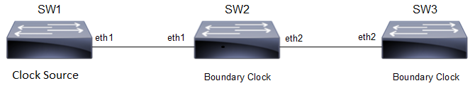
Configuration Topology
In this example, SW2 and SW3 are running PTP acting as boundary clock.
Boundary Clock Configuration
This section shows how to set up a boundary clock.
SW2 (boundary clock)
#configure terminal | Enter Configure mode |
(config)#bridge 1 protocol mstp | Create bridge 1 as an MSTP bridge (this step is not mandatory, but is a good practice to avoid layer 2 loops) |
(config)#synce | Enter configure Synchronous Ethernet mode. |
(config-synce)#synchronization option 1 | Set the synchronization network type. |
(config-synce)#exit | Exit Synce mode |
(config)#interface eth1 | Configure interface eth1 |
(config-if)#switchport | Configure eth1 as Layer 2 port |
(config-if)#bridge-group 1 | Configure eth1 in bridge group 1 |
(config-if)#synce | Enter interface Synchronous Ethernet mode. |
(config-if-synce)#mode synchronous | Configure synchronous mode. |
(config-if-synce)#input-source 2 | Configure the interface as an input source with priority 2. |
(config-if-synce)#exit | Exit Port Configure mode |
(conig-if)#exit | Exit Interface mode |
(config)#interface eth2 | Configure interface eth2 |
(config-if)#switchport | Configure eth2 as Layer 2 port |
(config-if)#bridge-group 1 | Configure eth2 in bridge group 1 |
(config-if)#synce | Enter interface Synchronous Ethernet mode. |
(config-if-synce)#mode synchronous | Configure synchronous mode. |
(config-if-synce)#output-source | Configure the interface as an output source. |
(config-if-synce)#exit | Exit Port Configure mode |
(config-if)#exit | Exit interface mode |
(config)#ptp clock 0 profile g8275.1 | Enables G8275.1 for PTP time/phase telecom profile |
(config-ptp-clk)#number-ports 2 | Configure the number of PTP ports on the instance |
(config-ptp-clk)#clock-port 2 | Configure ptp port |
(config-clk-port)#network-interface xe2 | Configure underlying interface that is used by this PTP Port |
(config-clk-port)#exit | Exit ptp clock port mode |
(config-ptp-clk)#clock-port 1 | Configure ptp port |
(config-clk-port)#network-interface xe1 | Configure underlying interface that is used by this PTP Port |
(config-clk-port)#exit | Exit ptp clock port mode |
SW3 (Boundary clock)
#configure terminal | Enter Configure mode |
(config)#bridge 1 protocol mstp | Create bridge 1 as an MSTP bridge (this step is not mandatory, but is a good practice to avoid layer 2 loops) |
(config)#synce | Enter configure Synchronous Ethernet mode. |
(config-synce)#synchronization option 1 | Set the synchronization network type. |
(config-synce)#exit | Exit Synce mode |
(config)#interface eth2 | Configure interface eth2 |
(config-if)#switchport | Configure eth2 as Layer 2 port |
(config-if)#bridge-group 1 | Configure eth2 in bridge group 1 |
(config-if)#synce | Enter interface Synchronous Ethernet mode. |
(config-if-synce)#mode synchronous | Configure synchronous mode. |
(config-if-synce)#input-source 4 | Configure the interface as an input source with priority 4. |
(config-if-synce)#exit | Exit Port Configure mode |
(config-if)#exit | Exit interface mode |
(config)#ptp clock 0 profile g8275.1 | Enables G8275.1 for PTP time/phase telecom profile |
(config-ptp-clk)#number-ports 2 | Configure the number of PTP ports on the instance |
(config-ptp-clk)#clock-port 2 | Configure ptp port |
(config-clk-port)#network-interface xe2 | Configure underlying interface that is used by this PTP Port |
(config-clk-port)#exit | Exit ptp clock port mode |
(config-clk-clk)#clock-port 1 | Configure ptp port |
(config-clk-port)#network-interface xe1 | Configure underlying interface that is used by this PTP Port |
(config-clk-port)#exit | Exit ptp clock port mode |
Validation
SW2
1. Verify the default data set on SW2.
#sh ptp clock 0 dataset
Default Dataset:
Two Step Flag : No
Clock Identity : B8:6A:97:FF:FE:F5:F4:C4
Number Of Ports : 2
Priority1 : 128
Priority2 : 128
Slave Only : No
Local Priority : 128
Max Steps Removed : 255
Domain Number : 24
Clock Quality :
Clock Class : 248
Clock Accuracy : 254
Offset ScaledLogVariance : 65535
2. Verify the port state on SW2.
#show ptp clock 0 port
Port 1:
Port State : Slave
Port Identity : B8:6A:97:FF:FE:F5:F4:C4:00:01
Log Min Delay Req Interval : -4
Peer Mean Path Delay : 0
Log Announce Interval : -3
Announce Receipt Timeout : 3
Log Sync Interval : -4
Delay Mechanism : End to end
Version Number : 2
Local Priority : 128
Master only : False
Signal Fail : False
Network Interface : xe1
Vlan Configured :
Description :
Foreign Master #0
L2 Address : e8:c5:7a:79:57:1d
Grandmaster clockIdentity : E8:C5:7A:FF:FE:2E:4B:1C
Port ID : E8:C5:7A:FF:FE:2E:4B:1C:00:01
clockClass : 135
Clock accuracy : 254
Offset scaled log variance : 65535
priority1 : 128
priority2 : 128
Steps removed : 0
PDV Scaled Allan Variance : 10
Received Packets : 7530
Discarded Packets : 4
Transmitted Packets : 3018
Peer #0
L2 Address : e8:c5:7a:79:57:1d
Clock Identity : e8:c5:7a:ff:fe:2e:4b:1c
Received Announce : 1021
Received Sync : 2042
Received Delay Response : 2041
Transmitted Delay Request : 2041
Port 2:
Port State : Master
Port Identity : B8:6A:97:FF:FE:F5:F4:C4:00:02
Log Min Delay Req Interval : -4
Peer Mean Path Delay : 0
Log Announce Interval : -3
Announce Receipt Timeout : 3
Log Sync Interval : -4
Delay Mechanism : End to end
Version Number : 2
Local Priority : 128
Master only : False
Signal Fail : False
Network Interface : xe2
Vlan Configured :
Description :
Received Packets : 0
Discarded Packets : 0
Transmitted Packets : 113
Note: Use show ptp stats to collect the PTP statistics and use clear ptp stats to clear the same.