Erbium-Doped Fiber Amplifier (EDFA) Configuration
Overview
Before the development of optical amplifiers, optical signals had to be converted into electrical signals, then amplified, and subsequently transformed back into optical signals. This was a very complicated and expensive process. To avoid this complexity, optical amplifiers are developed, enabling the direct amplification of optical signals without the need for conversion. This streamlined approach significantly reduced costs.
Various types of optical amplifiers include:
• Semiconductor Optical Amplifier (SOA)
• Raman Amplifiers
• Brillouin Amplifiers
• Erbium-Doped Fiber Amplifier (EDFA)
Erbium-Doped Fiber Amplifier (EDFA) uses erbium-doped fiber as an amplification medium and are extensively deployed in Wavelength Division Multiplexing (WDM) systems. It can amplify multiple optical signals simultaneously and is commonly used in the C-band and L-band.
System Description
Basically, the system will be developed to combine the input signal with the pump light using a WDM coupler. This combined signal is then directed into the EDF. Within the EDF, the pump light initiates a process called population inversion, and the input signal undergoes amplification through stimulated emission.
To ensure stable signal amplification and prevent undesired back reflections from the output port, isolators are strategically placed at both the input and output ends. Additionally, the presence of isolators prevents the amplifier from functioning as a laser.
The wavelength of the pump LD is precisely controlled and maintained close to 980nm.
These optical and communication systems operate in two different modes.
APC (Automatic Power Control)
In APC mode, the microprocessor controls the output power by adjusting the pump laser to maintain a predefined reference output power level. This control mechanism ensures the output power remains constant, even when the input power fluctuates within the dynamic range.
AGC (Automatic Gain Control)
In AGC mode, the microprocessor controls the output power to maintain the specified gain relative to the input power. The expected output power cannot be guaranteed, if the input power falls below the minimum assured input power range.
Objectives
The objective of this document is to provide the application of EDFA as a booster amplifier, Inline amplifier, and pre-amplifier.
• Booster Amplifier: The booster amplifier is placed just after the transmitter to increase the optical power launched to the transmission line. It’s not always required in single-channel links but is an essential part of the DWDM link where the multiplexer attenuates the signal channels. It has high input power, high output power, and medium optical gain.
• Inline Amplifier: The inline amplifiers are placed in the transmission line, compensating for the attenuation induced by the optical fiber. The in-line EDFA is designed for optical amplification between two network nodes on the main optical link. In-line EDFAs are placed every 80-100 km to ensure that the optical signal level remains above the noise floor. It features medium to low input power, high output power, high optical gain, and a low noise figure.
• Pre-Amplifier: The pre-amplifier is placed just before the receiver, such that sufficient optical power is launched to the receiver. It has relatively low input power, medium output power, and medium gain.
Support added for the DDM parameters specific to the EDFA available in the QSFP28 form factor. This application supports the reading of In-power, Out-power, pump BIAS, and gain. Additionally, it will enable the configuration of the target out-power and the continuous monitoring of these attributes in accordance with the specified thresholds.
Topology
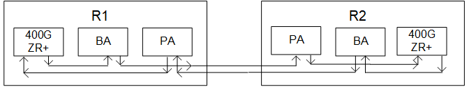
EDFA Sample Topology
Configuration
R1
#configure terminal | Enter into configure mode. |
(config)#interface ce15 | Enter into interface mode. |
(config-if)#edfa operating-mode agc | Enable the EDFA operating mode AGC. |
(config-if)#edfa target-gain 5 | Specify the desired EDFA gain value. |
(config-if)#commit | Commit the candidate configuration to the running configuration. |
(config-if)#exit | Exit the router mode. |
(config)#interface ce15 | Enter into interface mode. |
(config-if)#edfa operating-mode apc | Enable the EDFA operating mode APC. |
(config-if)# edfa target-outpwr 10 | Specify the desired EDFA output power value. |
(config-if)#commit | Commit the candidate configuration to the running configuration. |
(config-if)#exit | Exit the router mode. |
Validation
R1 - validation for AGC mode
#show running-config interface ce15
!
interface ce15
edfa operating-mode agc
edfa target-gain 5.000
verify is the gain value is applied after configuring.
ROUTER-1#show interface ce15 transceiver detail
Codes: * Not Qualified By IP Infusion, ** Not Supported By Module, -- No Power, - Not Applicable
Intf DDM InPwr AlertMax CritMax CritMin AlertMin
(dBm) (dBm) (dBm) (dBm) (dBm)
---------------------------------------------------------------------------
ce15 Active* -9.81 +5.00 +4.00 -20.97 -21.94
Intf DDM OutPwr AlertMax CritMax CritMin AlertMin
(dBm) (dBm) (dBm) (dBm) (dBm)
---------------------------------------------------------------------------
ce15 Active* -4.46 +20.00 +18.00 -10.00 -11.94
Intf DDM PumpBias AlertMax CritMax CritMin AlertMin
(Amp) (Amp) (Amp) (Amp) (Amp)
---------------------------------------------------------------------------
ce15 Active* +0.05 +0.59 +0.53 +0.00 +0.00
Intf DDM Gain AlertMax CritMax CritMin AlertMin
(dB) (dB) (dB) (dB) (dB)
---------------------------------------------------------------------------
ce15 Active* +3.67 +26.00 +25.00 +8.00 +7.00
R1 - validation for APC mode
#show running-config interface ce15
!
interface ce15
edfa operating-mode apc
edfa target-outpwr 10.000
R-1#show interface ce15 transceiver detail
Codes: * Not Qualified By IP Infusion, ** Not Supported By Module, -- No Power, - Not Applicable
Intf DDM InPwr AlertMax CritMax CritMin AlertMin
(dBm) (dBm) (dBm) (dBm) (dBm)
---------------------------------------------------------------------------
ce15 Active* -9.77 +5.00 +4.00 -20.97 -21.94
Intf DDM OutPwr AlertMax CritMax CritMin AlertMin
(dBm) (dBm) (dBm) (dBm) (dBm)
---------------------------------------------------------------------------
ce15 Active* +10.08 +20.00 +18.00 -10.00 -11.94
Intf DDM PumpBias AlertMax CritMax CritMin AlertMin
(Amp) (Amp) (Amp) (Amp) (Amp)
---------------------------------------------------------------------------
ce15 Active* +0.13 +0.59 +0.53 +0.00 +0.00
Intf DDM Gain AlertMax CritMax CritMin AlertMin
(dB) (dB) (dB) (dB) (dB)
---------------------------------------------------------------------------
ce15 Active* +19.85 +26.00 +25.00 +8.00 +7.00
*NOTE : after unconfiguring the edfa the value of output power and gain should be in default value.
Provide the following:
o Include a Topology diagram.
o Document configuration steps. Ensure the topology and configuration steps match.
o Request a show running-config for the new feature.
o Provide verification steps to demonstrate that the configuration has taken effect.
o Add a reference to any relevant information in the existing Configuration Guide.
Note: Request a "test report" before importing QA scenarios into your doc. Ensure you only include configurations samples that "Pass".