Overview
An MPLS Layer 2 Virtual Circuit (VC) is a point-to-point Layer 2 connection transported via MPLS on the service provider’s network. The Layer 2 circuit is transported over a single Label Switched Path (LSP) tunnel between two Provider Edge (PE) routers.
The following diagram illustrates the configuration steps in this section. In this sample, the VC host devices, Host1 and Host2, are connected to the Provider Edge (PE) router PE-1; and Host3 and Host4 are connected to PE-2. The VC is established between PE-1 and PE-2. Interface xe2, on PE-1 and PE-2, is connected to the customer network; xe1, on PE-1 and PE-2, is connected to the MPLS cloud.
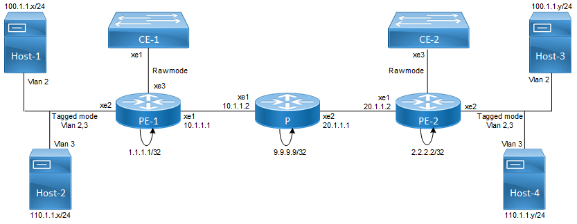
Figure 10-20: MPLS Layer 2 Virtual Circuit
The VC configuration process can be divided into the following steps:
Note: Loopback addresses being used should be advertised through OSPF, or should be statically routed.
1. Configure the IP address and OSPF for the PE-1, P (Provider), and PE-2 routers.
2. Configure MPLS and LDP on PE-1, P, and PE-2, and LDP targeted peer for the PE-1 and PE-2 routers. (If RSVP is used for configuring trunks, LDP must be configured on PE-1 and PE-2, and RSVP must be configured on PE-1, P, and PE-2.)
3. Configure the VC.
4. Bind the customer interface to the VC.
Last modified date: 10/17/2023