In-Band Ports
Any front-end ports of the device (in-band ports) can be made part of the management VRF. Once they are part of the management VRF they can also support all management applications such as SSH/Telnet and others as listed in Overview.
Once the ports are part of the management VRF, they should not be used for data traffic and routing or switching purposes. In-band ports can be added or removed from Management VRF as and when required.
#configure terminal | Enter configure mode |
(config)#interface xe1/1 | Enter interface mode |
(config-if)#ip vrf forwarding management | Add in-band port to Management VRF |
(config-if)#exit | Exit interface mode |
(config)#commit | Commit the candidate configuration to the running configuration |
(config)#exit | Exit configure mode |
#configure terminal | Enter configure mode |
(config)#interface xe1/1 | Enter interface mode |
(config-if)# no ip vrf forwarding management | Remove in-band port from Management VRF |
(config-if)#exit | Exit interface mode |
(config)#commit | Commit the candidate configuration to the running configuration |
(config)#exit | Exit configure mode |
Using Ping in Management VRF
To check reachability to any node in the management network, you need to explicitly mention the VRF name as “management.”
In the following example, Node-1 has management interface eth0 and Node-2 has management interfaces eth0 and xe3/1. In order to reach the network 20.20.20.40/24 from Node-1 a static route needs to added.
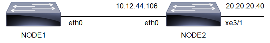
Figure 1-1: Ping in Management VRF topology
#configure terminal | Enter configure mode |
(config)# ip route vrf management 20.20.20.0/24 10.12.44.106 eth0 | Add static route in management VRF to reach 20.20.20.0/24 network |
(config)#commit | Commit the candidate configuration to the running configuration |
(config)#exit | Exit configure mode |
Node-1#show ip route vrf management
Codes: K - kernel, C - connected, S - static, R - RIP, B - BGP
O - OSPF, IA - OSPF inter area
N1 - OSPF NSSA external type 1, N2 - OSPF NSSA external type 2
E1 - OSPF external type 1, E2 - OSPF external type 2
i - IS-IS, L1 - IS-IS level-1, L2 - IS-IS level-2, ia - IS-IS inter area,
v - vrf leaked
* - candidate default
IP Route Table for VRF "management"
C 10.12.44.0/24 is directly connected, eth0
S 20.20.20.0/24 [1/0] via 10.12.44.106, eth0
Gateway of last resort is not set
Node-1#ping 20.20.20.40 vrf management
PING 20.20.20.40 (20.20.20.40) 56(84) bytes of data.
64 bytes from 20.20.20.40: icmp_seq=1 ttl=64 time=0.494 ms
64 bytes from 20.20.20.40: icmp_seq=2 ttl=64 time=0.476 ms
Last modified date: 10/19/2023