PIM Sparse-Dense Mode Configuration
Overview
Protocol Independent Multicast Sparse Mode-Dense Mode (PIM-SMDM) is a protocol designed to manage both sparse and dense multicast groups, efficiently handling varying multicast distribution patterns. In dense mode, it assumes listeners on all subnetworks, initially flooding the network and then pruning back areas without listeners. In sparse mode, it assumes few listeners and forwards traffic only to known listeners, reducing unnecessary transmission. PIM-SMDM switches between modes based on the multicast group's status, treating interfaces accordingly. A group is sparse if the router knows about a Rendezvous Point (RP) for it. Its adaptability makes it a versatile solution for diverse network scenarios.
Feature Characteristics
Protocol Independent Multicast Sparse Mode-Dense Mode (PIM-SMDM) manages both sparse and dense multicast groups, seamlessly switching modes based on the group's status. In dense mode, it floods the network with multicast traffic and prunes areas without listeners. In sparse mode, it forwards traffic only to known listeners, reducing unnecessary data transmission. The protocol treats interfaces as dense or sparse based on the group's mode, considering a group sparse if a Rendezvous Point (RP) is known. PIM-SMDM efficiently distributes multicast streams, optimizes network resources, and adapts to different multicast group modes, making it suitable for diverse network scenarios.
Benefits
• Manages both sparse and dense multicast groups simultaneously, making it adaptable to various network scenarios.
• Seamlessly switches between dense and sparse modes based on the multicast group's status, ensuring efficient distribution of multicast streams.
• Reduces unnecessary data transmission in sparse mode by forwarding traffic only to known listeners, optimizing the use of network resources.
• Can handle networks of different sizes and complexities, adapting to the number of listeners and the multicast group's distribution patterns.
• By pruning areas without listeners in dense mode and reducing traffic in sparse mode, PIM-SMDM enhances overall network performance and minimizes congestion.
• Treats interfaces as dense or sparse based on the group's mode, dynamically adapting to the network's current multicast requirements.
• Utilizes Rendezvous Points (RPs) in sparse mode for efficient centralized management of multicast sources and receivers.
• Suitable for a wide range of applications, from small-scale deployments to large, complex networks with varying multicast distribution needs.
Configuration
The required steps to configure PIM-SMDM are the following:
• Enable IP multicast on each PIM router (see Enabling IP Multicast Routing)
• Enable PIM-SMDM on the desired interfaces (see Enabling PIM-SMDM)
• Example for the group operating in sparse-mode having Static RP (see Configuring Rendezvous Point Statically for PIM-SMDM
• Example for the group operating in dense-mode having no RP
All multicast group states are dynamically maintained as the result of IGMP Report/Leave and PIM Join/Prune messages.This section provides the steps to configure the PIM-SMDM feature. Configuration steps and examples are used for two relevant scenarios. The following figure displays the network topology used in these examples.
Topology
There are two topologies for this sparse-dense mode configuration. Understanding these modes helps network administrators select the best multicast strategy for their network, ensuring efficient and reliable traffic delivery.
Sparse Mode
The network topology in Figure 2-1, includes several routers and hosts within a multicast network. Key components are Router_C, the Rendezvous Point (RP), and Host_1 and Host_2, which join a multicast group. Subnet 1 connects Host_1, Host_2, Router_E, and Router_F, with the latter two managing multicast traffic on the subnet.
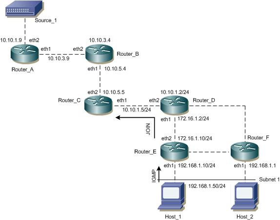
PIM-SMDM Configuration Topology (a)
Dense-mode
In the network topology shown in Figure 2-2, Source_1 (10.10.1.52) sends multicast data to group address 224.0.1.3. Host_1 shows interest in this group by sending an IGMP membership report, which Router_C processes to associate its eth1 interface with the group. As data packets flow from Source_1, each router creates an (S,G) entry in its multicast routing table. Router_C forwards the packets through eth1 to Host_1 and, having a downstream receiver, does not send a prune message to its upstream neighbor, Router_E, ensuring continuous delivery of multicast traffic to interested hosts.
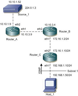
PIM-SMDM Configuration Topology (b)
Enabling IP Multicast Routing
To enable IP multicast routing on all of the PIM routers inside the PIM domain:
1. Enter the config mode.
R1(config)#configure terminal
2. Enable the IP Multicast routing.
(config)#ip multicast-routing
3. To commit the changes and exit.
(config)#commit
(config)#exit
Enabling PIM-SMDM
Enable PIM-SMDM on all participating interfaces within each of routers inside the PIM domain on which you want to run PIM. In the following sample configuration, both eth1 and eth2 are enabled for PIM-SMDM on the router.
1. Enter the config mode.
R1(config)#configure terminal
2. Configure the interface (eth1).
(config)#interface eth1
(config)#ip pim sparse-dense-mode
(config)#ip pim sparse-dense-mode
3. To commit the changes and exit.
(config)#commit
(config)#exit
4. Configure interface (eth2).
(config)#interface eth2
(config)#ip pim sparse-dense-mode
(config)#ip pim sparse-dense-mode
5. To commit the changes and exit.
(config)#commit
(config)#exit
Validation
Here is the sample configuration for Router_C:
hostname Router_C
!
interface eth0
!
interface eth1
ip pim sparse-dense-mode
!
interface eth2
ip pim sparse-dense-mode
!
interface lo
!
!
ip multicast-routing
The show ip pim interface command displays the interface details for Router_C.
Router_C#show ip pim interface
Address Interface VIFindex Ver/ Nbr
Mode Count
192.168.1.10 eth1 0 v2/SD 0
172.16.1.10 eth2 2 v2/SD 1
Sparse Mode Operation versus Dense Mode Operation
The following examples differentiates the group operating in sparse mode versus dense mode:
• Sparse mode operation when the RP is present for the group
• Dense mode operation when there is no RP for the group.
Sparse Mode Operation
Configuring Rendezvous Point Statically for PIM-SMDM
Every PIM multicast group needs to be associated with the IP address of a Rendezvous Point (RP), which is a router that resides in a multicast network domain. The address of the RP is used as the root of a group-specific distribution tree. All nodes in the domain that want to receive traffic sent to the group are aware of the address of the RP. For all senders to reach all receivers within a group, all routers in the domain must be able to map to the RP address configured for the group. There can be several RPs configured in a network deploying PIM-SM, each serving a different group.
You can statically configure a RP by specifying the RP address in every router in the PIM domain. The use of statically configured RPs is ideal for small network environments or ones that do not require many RPs and/or require changing the assignment of the RPs often. Changing the assignment of an RP requires the re-configuration of the RP address in all of the routers in the PIM domain.
In static RP configurations, RP failover is not available.
When configuring the RP statically, do the following:
• On every router, include the ip pim rp-address A.B.C.D statement even if a router does not have any source or group member attached to it
• Assign only one RP address for a multicast group in the PIM domain
The network topology shown in the Figure 2-1, includes several routers, a source, and hosts in different subnets.
• Source_1:
• Connected to Router_A via eth2 with IP address 10.10.1.9.
• Router_A:
• Interface eth1 connects to eth2 of Router_B with IP address 10.10.3.9.
• Interface eth2 connects to Source_1.
• Router_B:
• Interface eth1 connects to eth2 of Router_Awith IP address10.10.3.4.
• Interface eth2 connects to eth1 of Router_C with IP address 10.10.5.4.
• Router_C:
• Interface eth1 connects to eth2 of Router_Bwith IP address10.10.5.4.
• Interface eth2 connects to eth1 of Router_D with IP address 10.10.5.5 and 10.10.1.5/24 network.
• Router_D:
• Interface eth1 connects to eth2 of Router_C with IP address 10.10.1.2/24.
• Interface eth2 connects to eth1 of Router_E with IP address 172.16.1.2/24.
• Router_E:
• Interface eth1 connects to eth2 of Router_D with IP address 172.16.1.2/24.
• Interface eth2 connects to eth1 of Router_F with IP address 172.16.1.10/24.
• Interface eth1 connects to Host_1 via IGMP with IP address 192.168.1.10/24.
• Router_F:
• Interface eth1 connects to eth2 of Router_E with IP address 172.16.1.10/24.
• Interface eth1 connects to Host_2 with IP address 192.168.1.50/24.
• Host_1:
• Connected to Router_E with IP address 192.168.1.10/24.
• Host_2:
• Connected to Router_F with IP address 192.168.1.50/24.
Configure Static RP
1. Enter the config mode.
R1(config)#configure terminal
2. Configure interface (eth1).
(config)#ip pim rp-address 10.10.1.5
3. To commit the changes and exit.
(config)#commit
(config)#exit
Validation
Here is the sample configuration for Router_D:
hostname Router_D
!
interface eth0
!
interface eth1
ip pim sparse-dense-mode
!
interface eth2
ip pim sparse-dense-mode
!
interface lo
!
!
ip multicast-routing
ip pim rp-address 10.10.1.5
!
RP Details
At Router_D, the show ip pim rp mapping command shows that 10.10.1.5 is the RP for all multicast groups 224.0.0.0/4, and is statically configured. All other routers will have a similar output:
Router_D#sh ip pim rp mapping
PIM Group-to-RP Mappings
Override RP cnt: 0
Group(s): 224.0.0.0/4, Static
RP: 10.10.1.5
Uptime: 00:01:45
At Router_D, use the show ip pim rp-hash command to display the selected RP for a specified group (224.0.1.3):
Router_D#show ip pim rp-hash 224.0.1.3
RP: 10.10.5.37
Interface Details
The show ip pim interface command displays the interface details for Router_E, and shows that Router_E is the Designated Router on Subnet 1.
Router_E#show ip pim interface
Address Interface VIFindex Ver/ Nbr DR DR
Mode Count Prior
192.168.1.10 eth1 0 v2/SD 1 1 192.168.1.10
172.16.1.10 eth2 2 v2/SD 1 1 172.16.1.10
IP Multicast Routing Table
Note: The multicast routing table displays for an RP router are different from other routers.
The show ip pim mroute command displays the IP multicast routing table. In this table, the following fields are defined:
RPF nbr
Displays the unicast next-hop to reach RP.
and mask length.
RPF idx
Displays the incoming interface for this (*, G) state.
RP
Displays the IP address for the RP router
B
Displays the bidirectional pim mode
The leading dots ....
Stand for VIF index
Router_E#show ip pim mroute
IP Multicast Routing Table
(*,*,RP) Entries: 0
(*,G) Entries: 1
(S,G) Entries: 0
(S,G,rpt) Entries: 0
(*, 224.0.1.3)
RP: 10.10.1.5
RPF nbr: 172.16.1.2
RPF idx: eth2
Upstream State: JOINED
Local ................................
Joined j...............................
Asserted ................................
Outgoing o...............................
At Router_E, eth2 is the incoming interface of the (*, G) entry, and eth1 is on the outgoing interface list of the
(*, G) entry. This means that there is a group member through eth1, and the RP is reachable through eth2.
(*, G) entry. This means that there is a group member through eth1, and the RP is reachable through eth2.
The 0 position on this 32-bit index is for eth1 (as illustrated in the interface display above). The j on the 0 index indicates that the Join has come from eth1.
Since Router_C is the RP, and the root of this multicast tree, the show ip pim mroute command on Router_C shows RPF nbr as 0.0.0.0 and RPF idx as none.
Router_C#show ip pim mroute
IP Multicast Routing Table
(*,*,RP) Entries: 0
(*,G) Entries: 1
(S,G) Entries: 0
(S,G,rpt) Entries: 0
(*, 224.0.1.3)
RP: 10.10.1.5
RPF nbr: 0.0.0.0
RPF idx: None
Upstream State: JOINED
Local ................................
Joined j...............................
Asserted ................................
Outgoing o...............................
For configuring Rendezvous point dynamically refer Configure Rendezvous Point Dynamically Using Bootstrap Router Method and Configuring Rendezvous Point Statically
Dense-mode Operation
The network topology described in Figure 2-2, the Source_1 address is 10.10.1.52 and the group address is set to 224.0.1.3.
In this example all routers are running PIM-SMDM.
• Host_1 sends an IGMP membership report to Subnet 1.
• After Router_C receives this report, it associates its receiving interface, eth1, with the group reported in the IGMP message, for example, group1.
• Source_1 then sends a data packet for group1.
• Every router creates an (S,G) entry in the multicast routing table.
• When the data packet reaches Router_C, it forwards via the interface, eth1, because there is a local member on this interface for this group. Router_C has a downstream receiver, so it does not send a prune message to its upstream neighbor router, Router_E.
The network topology shown in the Figure 2-2, includes a source, three routers, and a host in a subnet.
• Source_1:
• Connected to Router_A via eth2 with IP address 10.10.1.52 and sending multicast traffic to the multicast group 224.0.1.3.
• Router_A:
• Interface eth1 connects to eth2 of Router_B with IP address 10.10.3.9.
• Interface eth2 connects to Source_1 with IP address 10.10.1.9.
• Router_B:
• Interface eth1 connects to eth2 of Router_A with IP address 10.10.3.4.
• Interface eth2 connects to eth1 of Router_C with IP address 172.16.1.2/24.
• Router_C:
• Interface eth1 connects to eth2 of Router_B with IP address 172.16.1.2/24.
• Interface eth2 connects to Host_1 via eth1 with IP address 172.16.1.10/24.
• Interface eth1 connects to Host_1 with IP address 192.168.1.10/24 and 192.168.1.50/24 via IGMP.
• Host_1:
• Connected to Router_C with IP address 192.168.1.50/24 and subscribed to the multicast group 224.0.1.3 via IGMP.
Validation
Enter the commands listed in this section to confirm the previous configurations.
IP Multicast Routing Table
The show ip pim mroute command displays the IP multicast routing table.
Router_C#show ip mroute
IP Multicast Routing Table
Flags: I - Immediate Stat, T - Timed Stat, F - Forwarder installed
Timers: Uptime/Stat Expiry Interface State:
Interface (TTL) (10.10.1.52, 224.0.1.3), uptime 00:00:15
Owner PIM-DM, Flags: F
Incoming interface: eth2
Outgoing interface list:
eth1 (1)
IP PIM-SMDM Multicast Routing Table
The show ip pim dense-mode mroute command displays the IP PIM-DM multicast routing table
Router_C#show ip pim mroute
PIM-DM Multicast Routing Table (10.10.1.52, 224.0.1.3)
RPF Neighbor: 172.16.1.2, Nexthop: 172.16.1.2, eth2
Upstream IF: eth2
Upstream State: Forwarding
Assert State: NoInfo
Downstream IF List:
eth1, in 'olist': Downstream State: NoInfo Assert State: NoInfo