PFC with QoS Configuration
Overview
Priority-based Flow Control (PFC) provides a priority-level flow control mechanism that operates independently for each frame priority. Its primary purpose is to ensure zero packet loss (lossless behavior) during periods of congestion in Data Center Bridging (DCB) networks.
By default, Quality of Service (QoS) functions with a lossy behavior.By default, Class of Service (CoS) priorities are mapped one-to-one with queues. For instance, CoS 0 traffic is assigned to queue 0. If queue 0 is configured as lossless, Priority Flow Control (PFC) will be triggered for that queue.
Note: PFC with QoS functionality is limited to known unicast and tagged traffic.
The objective of this section is to enable PFC support alongside QoS, when congestion occurs on device or peer device node.
Benefits
Enable lossless behavior for specific traffic classes while maintaining traffic prioritization by integrating Priority Flow Control (PFC) with Quality of Service (QoS) profiles for designated priorities.
PFC Configuration when Congestion on Device
This section outlines the steps for configuring Priority Flow Control (PFC) and verifying its functionality when congestion occurs on the device (Device1). The setup uses VLAN 100 traffic with CoS priority 0 and ensures proper flow control by applying a shaper on the egress interface of Device1.
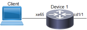
Topology
The topology consist of a client that act as Traffic Generator (TG) to send traffic to Device 1 on interface xe65 Device1.
PFC for Traffic Congestion on Device
PFC Procedure when Congestion on Device
Use this procedure is to apply PFC when congestion occurs on Device1.
1. Enable Data Center Bridging (DCB) and Priority-based Flow Control (PFC) on the bridge on Device 1.
!
bridge 1 protocol ieee vlan-bridge
!
vlan database
vlan-reservation 4001-4094
!
vlan 100 bridge 1 state enable
priority-flow-control enable bridge 1
2. Configure queue 0 as lossless with priority enabled in the default queuing policy.
!
policy-map type queuing default default-out-policy
class type queuing default q0
priority
lossless
exit
!
!
interface cd1/1
shape rate 100 mbps burst 1000
!
3. Configure egress port cd1/1 and ingress xe65 Interfaces. Following sample commands, configures interface cd1/1 with rate shaping at 100 Mbps and MTU as 9216 for jumbo frames and interface xe65 with PFC priority as 0.
!
interface cd1/1
description connected to DUT2-7040
switchport
bridge-group 1
switchport mode trunk
switchport trunk allowed vlan all
load-interval 30
mtu 9216
shape rate 100 mbps burst 1000
!
!
interface xe65
description connected spirent
switchport
bridge-group 1
switchport mode trunk
switchport trunk allowed vlan all
priority-flow-control mode on
priority-flow-control enable priority 0
load-interval 30
mtu 9216
!
4. Configure the Traffic Generator (TG) to send traffic to VLAN-tagged traffic on VLAN 100. Set Class of Service (CoS) to 0. Ensure the TG is connected to interface xe65 on Device1. Send bidirectional traffic or add a static MAC entry via CLI to ensure unicast forwarding.
5. Send traffic at a rate exceeding the 100 Mbps shaping rate on interface cd1/1 to create congestion, causing queue 0 to fill up and trigger PFC for priority 0.
Validations
Execute the following command on Device1 to check PFC statistics:
#show priority-flow-control statistics bridge 1
bridge : 1
interface pri pause sent pause received
===========================================
xe65 0 7819702 0
xe65 1 0 0
xe65 2 0 0
xe65 3 0 0
xe65 4 0 0
xe65 5 0 0
xe65 6 0 0
xe65 7 0 0
Column Heading | Description |
|---|---|
Pause Sent (7819702): | Indicates that the Device 1 has generated PFC frames for priority 0 to notify the peer device to pause traffic. |
Pause Received (0): | Indicates that no PFC frames were received from the peer device. |
#show interface counters rate mbps
+-------------------+--------------+-------------+--------------+-------------+
| Interface | Rx mbps | Rx pps | Tx mbps | Tx pps |
+-------------------+--------------+-------------+--------------+-------------+
cd1/1 0.00 1 100.01 97668
xe65 100.01 97669 1.04 2037
#
PFC Configuration when Congestion on Peer Device
This section outlines the steps for configuring PFC and verifying its functionality when congestion occurs on the peer device (Device2). The setup uses VLAN 100 traffic with CoS priority 0 and ensures proper flow control by applying a shaper on the egress interface of Device2.
Topology
The topology consist two clients that act as Traffic Generator (TG), Device 1 and 2. The TG client sends VLAN 100 traffic with CoS 0 to simulate congestion. The Device 1 egress interface cd1/1 is connected to Device2 with PFC for priority 0. On Device2 egress interface xe33, the congestion is induced by applying a traffic shaper to the egress interface.

PFC for Congestion on Peer Device
Procedure
On Router1
1. Ensure the VLAN is configured and mapped to bridge group 1 and PFC is enabled on Device 1.
!
bridge 1 protocol ieee vlan-bridge
!
vlan database
vlan-reservation 4001-4094
!
vlan 100 bridge 1 state enable
priority-flow-control enable bridge 1
2. Ensure QoS is enabled. Following sample commands, configure queue 0 as lossless with priority enabled in the default queuing policy.
!
policy-map type queuing default default-out-policy
class type queuing default q0
priority
lossless
exit
!
3. Configure ingress and egress interfaces for PFC. Following sample commands, configures interface cd1/1 and xe65 with MTU as 9216 for jumbo frames, PFC priority as 0 and interface xe65 with QoS policy as 0 on incoming traffic.
!
interface cd1/1
description connected to DUT2-7040
switchport
bridge-group 1
switchport mode trunk
switchport trunk allowed vlan all
priority-flow-control mode on
priority-flow-control enable priority 0
load-interval 30
mtu 9216
!
!
interface xe65
description connected spirent
switchport
bridge-group 1
switchport mode trunk
switchport trunk allowed vlan all
priority-flow-control mode on
priority-flow-control enable priority 0
load-interval 30
mtu 9216
!
On Router 2
1. Login to peer Device 2 and verify VLAN 100 is mapped to bridge group 1. Ensure PFC is enabled.
!
bridge 1 protocol ieee vlan-bridge
!
vlan database
vlan-reservation 4001-4094
vlan 100 bridge 1 state enable
priority-flow-control enable bridge 1
2. Ensure QoS Policy is enabled and configured to assign VLAN 100 traffic with rate shaping at 100 Mbps on egress interface.
!
qos enable
qos statistics
interface xe33
shape rate 100 mbps burst 1000
!
3. Configure ingress cd1/1 and egress xe33 interfaces. Following sample commands, configures MTU as 9216 for frames, PFC priority as 0 on interface cd1/1. And shape rate at 100 Mbps for the incoming traffic from TG on interface xe33.
!
interface cd1/1
description connected to DUT1-7043
switchport
bridge-group 1
switchport mode trunk
switchport trunk allowed vlan all
priority-flow-control mode on
priority-flow-control enable priority 0
load-interval 30
mtu 9216
!
!
interface xe33
description connected to spirent
switchport
bridge-group 1
switchport mode trunk
switchport trunk allowed vlan all
load-interval 30
mtu 9216;
shape rate 100 mbps burst 1000
!
4. Configure the TG to send VLAN 100 traffic with priority 0 to Device2. The TG sends traffic at shaping rate exceeding 100 Mbps to create congestion on the egress xe33 interface. Ensure the TG is connected to interface xe33 on Device2. Send bidirectional traffic or add a static MAC entry via CLI to ensure unicast forwarding.
5. Verify the PFC Statistics Device 1 and 2.
Validation
Execute the following command on Device1 to check PFC activity.
#show priority-flow-control statistics bridge 1
bridge : 1
interface pri pause sent pause received
===========================================
xe65 0 190297 0
xe65 1 0 0
xe65 2 0 0
xe65 3 0 0
xe65 4 0 0
xe65 5 0 0
xe65 6 0 0
xe65 7 0 0
cd1/1 0 0 190436
cd1/1 1 0 0
cd1/1 2 0 0
cd1/1 3 0 0
cd1/1 4 0 0
cd1/1 5 0 0
cd1/1 6 0 0
cd1/1 7 0 0
Column Heading | Description |
|---|---|
Pause Sent (190297): | Device1 generates PFC pause frames on xe65 for priority 0 to notify the traffic generator to pause traffic. |
Pause Received (190436): | Device1 receives pause frames on cd1/1 from Device2 for priority 0, indicating congestion on Device2. |
#show interface counters rate mbps
+-------------------+--------------+-------------+--------------+-------------+
| Interface | Rx mbps | Rx pps | Tx mbps | Tx pps |
+-------------------+--------------+-------------+--------------+-------------+
cd1/1 0.64 1253 100.02 97671
xe65 100.02 97673 0.64 1253
#
Execute the following command on Device2 to check PFC activity.
#show priority-flow-control statistics bridge 1
show priority-flow-control statistics bridge 1
bridge : 1
interface pri pause sent pause received
===========================================
cd1/1 0 323455 0
cd1/1 1 0 0
cd1/1 2 0 0
cd1/1 3 0 0
cd1/1 4 0 0
cd1/1 5 0 0
cd1/1 6 0 0
cd1/1 7 0 0
Column Heading | Description |
|---|---|
Pause Sent (323455) | Device2 generates PFC pause frames for priority 0 to notify Device1 to slow down traffic due to congestion on xe33. |
#show interface counters rate mbps
+-------------------+--------------+-------------+--------------+-------------+
| Interface | Rx mbps | Rx pps | Tx mbps | Tx pps |
+-------------------+--------------+-------------+--------------+-------------+
cd1/1 100.01 97669 0.64 1253
xe33 0.00 1 100.01 97669
#
PFC Configuration for Ingress Service Policy Map
This section outlines the steps for configuring PFC for ingress service policy map.
Topology
Refer to the Topology given in PFC Configuration when Congestion on Peer Device.
Configuration On Device1
1. Ensure the VLAN is configured and mapped to bridge group 1 and PFC is enabled on Device 1.
!
bridge 1 protocol ieee vlan-bridge
!
vlan database
vlan-reservation 4001-4094
!
vlan 100 bridge 1 state enable
priority-flow-control enable bridge 1
2. Ensure QoS is enabled. Configure QoS Polices, class and statistics. Following sample configures Class c1 matches UDP traffic on source port 4791, and policy p1 maps this traffic to queue 4.
qos enable
qos statistics
!
class-map type qos match-all c1
match layer4 udp source-port 4791
!
policy-map type qos p1
class type qos c1
set queue 4
exit
!
3. Configure queue 4 as lossless with priority enabled in the default queuing policy.
!
policy-map type queuing default default-out-policy
class type queuing default q0
priority
lossless
exit
!
class type queuing default q4
priority
lossless
exit
!
!
interface cd1/1
shape rate 100 mbps burst 1000
!l
interface xe65
service-policy type qos input p1
!
4. Configure egress cd1/1 and ingress xe65 Interfaces. Following sample commands, configures interface cd1/1 with rate shaping at 100 Mbps and MTU as 9216 for jumbo frames and interface xe65 with PFC priority as 4 and QoS policy as p1 on incoming traffic.
!
interface cd1/1
description connected to DUT2-7040
switchport
bridge-group 1
switchport mode trunk
switchport trunk allowed vlan all
load-interval 30
mtu 9216
shape rate 100 mbps burst 1000
!
interface xe65
description connected spirent
switchport
bridge-group 1
switchport mode trunk
switchport trunk allowed vlan all
priority-flow-control mode on
priority-flow-control enable priority 4
load-interval 30
mtu 9216
service-policy type qos input p1
!
5. Configure the Traffic Generator (TG) to send traffic to VLAN-tagged traffic on VLAN 100. Set Class of Service (CoS) to 4. Ensure the TG is connected to interface xe65.
6. Send traffic at a rate exceeding the 100 Mbps shaping rate on interface cd1/1 to create congestion, causing queue 4 to fill up and trigger PFC for priority 4.
Validation
Execute the following command to check PFC statistics
#show priority-flow-control statistics bridge 1
bridge : 1
interface pri pause sent pause received
======================================================
xe65 0 0 0
xe65 1 0 0
xe65 2 0 0
xe65 3 0 0
xe65 4 369553 0
xe65 5 0 0
xe65 6 0 0
xe65 7 0 0
cd1/1 0 0 0
cd1/1 1 0 0
cd1/1 2 0 0
cd1/1 3 0 0
cd1/1 4 0 369172
cd1/1 5 0 0
cd1/1 6 0 0
cd1/1 7 0 0
#show interface counters rate mbps
+-------------------+--------------+-------------+--------------+-------------+
| Interface | Rx mbps | Rx pps | Tx mbps | Tx pps |
+-------------------+--------------+-------------+--------------+-------------+
cd1/1 0.64 1253 100.01 97665
xe65 100.01 97668 0.64 1253
#show policy-map interface xe65
Interface xe65
Type QoS statistics status : enabled
Type QoS Ingress policy-map : p1
Class-map (qos): c1 (match all)
match layer4 udp source-port 4791
set queue 4
matched : 29714724 packets, 3803484672 bytes
transmitted : 29714724 packets, 3803484672 bytes
Type Queuing policy-map : default-out-policy
Class-map (queuing): q0
priority
output : 0 packets, 0 bytes
dropped : 0 packets, 0 bytes
Class-map (queuing): q1
priority
output : 0 packets, 0 bytes
dropped : 0 packets, 0 bytes
Class-map (queuing): q2
priority
output : 0 packets, 0 bytes
dropped : 0 packets, 0 bytes
Class-map (queuing): q3
priority
output : 0 packets, 0 bytes
dropped : 0 packets, 0 bytes
Class-map (queuing): q4
priority
lossless
output : 304 packets, 38912 bytes
dropped : 0 packets, 0 bytes
Class-map (queuing): q5
priority
output : 0 packets, 0 bytes
dropped : 0 packets, 0 bytes
Class-map (queuing): q6
priority
output : 0 packets, 0 bytes
dropped : 0 packets, 0 bytes
Class-map (queuing): q7
priority
output : 0 packets, 0 bytes
dropped : 0 packets, 0 bytes
Class-map (queuing): mc-q0
output : 0 packets, 0 bytes
dropped : 0 packets, 0 bytes
Class-map (queuing): mc-q1
output : 0 packets, 0 bytes
dropped : 0 packets, 0 bytes
Class-map (queuing): mc-q2
output : 0 packets, 0 bytes
dropped : 0 packets, 0 bytes
Class-map (queuing): mc-q3
output : 0 packets, 0 bytes
dropped : 0 packets, 0 bytes
Wred/Tail Drop Statistics :
----------------------
green : 0 packets
yellow : 0 packets
red : 0 packets
#
Configuration On Device 2
1. Login to peer Device 2 and verify VLAN 100 is mapped to bridge group 1. Ensure PFC is enabled.
!
bridge 1 protocol ieee vlan-bridge
!
vlan database
vlan-reservation 4001-4094
vlan 100 bridge 1 state enable
priority-flow-control enable bridge 1
2. Ensure QoS Policy is enabled and configured to assign VLAN 100 traffic with rate shaping at 100 Mbps on ingress interface.
!
qos enable
qos statistics
interface xe33
shape rate 100 mbps burst 1000
!
3. Configure ingress cd1/1 and egress xe33 interfaces. Following sample commands, configures MTU as 9216 for frames, PFC priority as 4 on interface cd1/1. And shape rate at 100 Mbps for the incoming traffic from TG on interface xe33.
!
interface cd1/1
description connected to DUT1-7043
switchport
bridge-group 1
switchport mode trunk
switchport trunk allowed vlan all
priority-flow-control mode on
priority-flow-control enable priority 4
load-interval 30
mtu 9216
!
!
interface xe33
description connected to spirent
switchport
bridge-group 1
switchport mode trunk
switchport trunk allowed vlan all
load-interval 30
mtu 9216
shape rate 100 mbps burst 1000
!
4. Send bidirectional traffic on the egress xe33 interface.
5. Verify the PFC Statistics on Device 2.
Validation
Execute the following command on Device2 to check PFC activity.
#show priority-flow-control statistics bridge 1
bridge : 1
interface pri pause sent pause received
======================================================
cd1/1 0 0 0
cd1/1 1 0 0
cd1/1 2 0 0
cd1/1 3 0 0
cd1/1 4 519152 0
cd1/1 5 0 0
cd1/1 6 0 0
cd1/1 7 0 0
#show interface counters rate mbps
+-------------------+--------------+-------------+--------------+-------------+
| Interface | Rx mbps | Rx pps | Tx mbps | Tx pps |
+-------------------+--------------+-------------+--------------+-------------+
cd1/1 100.01 97666 0.64 1253
xe33 0.00 1 100.01 97671
#