Topology
The diagram below illustrates the configuration example in this chapter. Interfaces eth2 on PE1 and eth3 on PE2 are connected to the customer network (Host3 and Host 4). Interfaces eth1 on PE1 and eth2 on PE2 are connected to the MPLS-TP cloud. The following is a summary of the VC configuration process:
• Configure the VC
• Bind the customer interface to the VC
• Map the VC to the tunnel
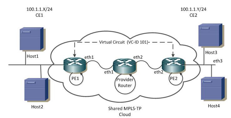
Figure 14-1: Layer 2 Virtual Circuit
The configurations are based on the network shown in Figure 14-1.
• For tunnel connectivity, refer to Figure 13-1.
• For details about configuring a co-routed tunnel, refer to Co-Routed Bi-Directional Tunnel.
Last modified date: 07-13-2023