MPLS-TP Layer 2 Virtual Circuit
The MPLS-TP Layer 2 Virtual Circuit (VC) is a point-to-point Layer-2 connection that is transported by a Multi-Protocol Label Switching Transport Profile (MPLS-TP) on the service provider’s network. The Layer 2 circuit is transported over a single Label Switched Path (LSP) tunnel between two Provider Edge (PE) routers.
Topology
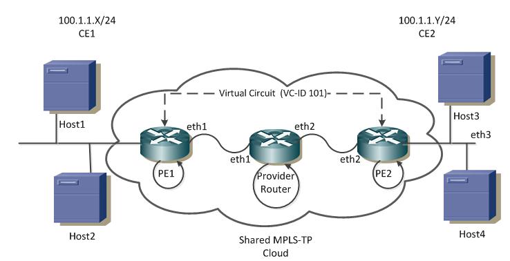
The diagram below illustrates the configuration example in this chapter. Interfaces eth2 on PE1 and eth3 on PE2 are connected to the customer network (Host3 and Host 4). Interfaces eth1 on PE1 and eth2 on PE2 are connected to the MPLS-TP cloud. The following is a summary of the VC configuration process:
• Configure the VC
• Bind the customer interface to the VC
• Map the VC to the tunnel
Layer 2 Virtual Circuit
The configurations are based on the network shown in Figure 17-1.
• For tunnel connectivity, refer to Figure 16-1.
• For details about configuring a co-routed tunnel, refer to Co-Routed Bi-Directional Tunnel.
Configure Virtual Circuit
Each VC ID uniquely identifies the Layer 2 circuit among all the Layer-2 circuits.
Note: Both PE routers (endpoints) must be configured with the same VC-ID.
PE1 (NSM)
#configure terminal | Enter configure mode. |
(config)#mpls l2-circuit VC-1 101 300 3.3.3.3 200 grp-1 manual | Configure the virtual circuit (VC) for PE2. In this example, VC-1 is the VC name, 101 is the VC ID, 300 is the peer global ID, 3.3.3.3 is the VC endpoint node ID, 200 is VC endpoint, AC-ID grp-1 is the group name. |
PE2 (NSM)
#configure terminal | Enter configure mode. |
(config)#mpls l2-circuit VC-1 101 100 1.1.1.1 200 grp-1 manual | Configure the virtual circuit (VC) for PE1. In this example, VC-1 is the VC name, 101 is the VC ID, 100 is the peer global ID, 1.1.1.1 is the VC endpoint node ID, 200 is VC endpoint, VC is VC-ID, grp-1 is the group name. |
Bind Customer Interface to VC
Attach the Customer Interface to the VC.
Note: Layer 2 VCs can only be bound to Layer 2 interfaces. VC encapsulation should be Ethernet (default), VLAN, HDLC or PPP.
Layer-2 Untagged Traffic
Use Access mode for Layer 2 untagged traffic.
PE1 (NSM)
#configure terminal | Enter configure mode. |
(config)#bridge 1 protocol ieee vlan- bridge | Configure the VLAN for bridge 1. |
(config)#interface eth2 | Enter interface mode. |
(config-if)#switchport | Switch to Layer 2 mode. |
(config-if)#bridge-group 1 | Associate the eth2 interface with bridge group 1. |
(config-if)#switchport mode access | Set the switching characteristics of this interface to access mode. |
(config-if)#mpls-tp service-interface type layer-2 200 | Configure the service interface.in this example, local AC-ID is 200. |
(config-if)#mpls-l2-circuit VC-1 ethernet | Bind the access interface to the Ethernet VC. |
PE2 (NSM)
#configure terminal | Enter configure mode. |
(config)#bridge 1 protocol ieee vlan- bridge | Specify the VLAN for bridge 1. |
(config)#interface eth3 | Enter interface mode. |
(config-if)#switchport | Switch to Layer 2 mode. |
(config-if)#bridge-group 1 | Associate the eth3 interface with bridge group 1. |
(config-if)#switchport mode access | Set the switching characteristics of this interface to Access mode. |
(config-if)#mpls-tp service-interface type layer-2 200 | Configure the service interface.In this example, local AC-ID is 200. |
(config-if)#mpls-l2-circuit VC-1 ethernet | Bind the interface to the VC. |
Layer-2 Tagged Traffic
Use
Trunk mode for Layer 2 tagged traffic. The following configuration allows only VLAN 2 and 3 traffic.
PE1
#configure terminal | Enter configure mode. |
(config)#bridge 1 protocol ieee vlan- bridge | Specify the VLAN for bridge 1. |
(config)#mpls l2-circuit VC-2 201 300 3.3.3.3 200 grp-1 | Configure the VC for PE2. In this example, VC-2 is the VC name, 201 is the VC ID, 300 is the peer global ID, 3.3.3.3 is the VC endpoint node ID, 200 is VC endpoint VC-ID and grp-1 is the group name. |
(config-pseudowire)#control-word | Enable Control-word. |
(config-pseudowire)#manual-pseudowire | Configure pseudowire manual (no signaling). |
(config-pseduowire)#exit | Exit pseudowire mode. |
(config)#vlan database | Enter the VLAN configuration mode. |
(config-vlan)#vlan 2 bridge 1 | Enable the state of VLAN 2 on bridge 1. |
(config-vlan)#exit | Exit the VLAN configuration mode. |
(config)#interface eth2 | Enter interface mode. |
(config-if)#switchport | Switch to Layer 2 mode. |
(config-if)#bridge-group 1 | Associate the eth2 interface with bridge group 1. |
(config-if)#switchport mode trunk | Configure the switching characteristics of this interface to Trunk mode. |
(config-if)#switchport trunk allowed vlan add 2 | Enable VLAN ID 2 on this port. |
(config-if)#mpls-tp service-interface type layer-2 200 | Configure the service interface.in this example local AC-id is 200. |
(config-if)#mpls-l2-circuit VC-2 vlan 2 | Allow VLAN 2 traffic on this VC. |
PE2
#configure terminal | Enter configure mode. |
(config)#bridge 1 protocol ieee vlan- bridge | Specify the VLAN for bridge 1. |
(config)#mpls l2-circuit VC-2 201 100 1.1.1.1 200 grp-1 | Configure the VC for PE2. In this example, VC-2 is the VC name, 201 is the VC ID and 1.1.1.1 is the VC endpoint node-id. |
(config-pseudowire)#control-word | Enable Control-word. |
(config-pseudowire)#manual-pseudowire | Configure pseudowire manual (no signaling). |
(config-pseduowire)#exit | Exit pseudowire mode. |
(config)#interface eth3 | Enter interface mode. |
(config-if)#switchport | Switch to Layer 2 mode. |
(config-if)#bridge-group 1 | Associate the eth1 interface with bridge group 1. |
(config-if)#switchport mode trunk | Configure the switching characteristics of this interface to Trunk mode. |
(config-if)#switchport trunk allowed vlan add 2 | Enable VLAN ID 2 on this port. |
(config-if)#mpls-tp service-interface type layer-2 200 | Configure the service interface.in this example local AC-id is 200. |
(config-if)#mpls-l2-circuit VC-2 vlan 2 | Allow VLAN 2 traffic on this VC. |
Map VC to Tunnel
PE1 (NSM)
#configure terminal | Enter configure mode. |
(config)#mpls l2-circuit-fib-entry 101 1111 2222 tp-tunnel tnl1 eth2 | Configured an FIB entry. In this example, 111 is the incoming label, 2222 is the outgoing label, 3.3.3.3 is the endpoint, eth2 is the AC interface name, and tnl1 is the tunnel name. |
PE2 (NSM)
#configure terminal | Enter configure mode. |
(config)#mpls l2-circuit-fib-entry 101 2222 1111 tp-tunnel tnl2 eth3 | Configure an FIB entry. In this example, 2222 is the incoming label, 1111 is the outgoing label, 3.3.3.3 is the endpoint, eth3 is the AC interface name, and tnl2 is the tunnel name. |
Validation
For a correct configuration, the following commands should provide these results:
• Status is Active in the show mpls vc-table command on ingress/egress for the configured virtual circuit
• Ping from CE1 to CE2 is successful
Validation is displayed in the following example. The command used to display Layer 2 virtual circuit information:
• show mpls mapped-routes (in the NSM daemon)
#show mpls vc-table
VC-ID Vlan-ID Inner-Vlan-ID Access-Intf Network-Intf Out Label tunnel-Label Nexthop Status
100 2 N/A eth1 eth2 1111 2001 N/A Active