SAToP Configuration
Structure agnostic TDM over PSN (SATop) emulates an end-to-end TDM circuit over MPLS. This feature creates a pseudowire between two end points over MPLS as defined in RFC 4447.
SAToP Pseudowire Creation
This procedure show how to establish the pseudowire between provider edge routers. The configuration assumes that you are running the ospfd, ldpd, mstpd, nsm, and imi daemons.
Topology
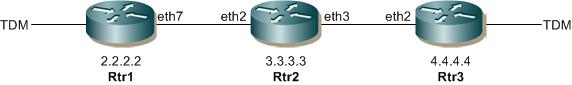
Three router topology for PW creation
Rtr1
#configure terminal | Enter configure mode |
(config)#hostname Rtr1 | Configure the name of the host as Rtr1 |
Rtr1(config)#interface eth7 | Enter interface mode |
Rtr1(config-if)#ip address 1.1.1.1/24 | Assign IP address 1.1.1.1 to the interface |
Rtr1(config-if)#exit | Exit interface mode |
Rtr1(config)#int lo | Enter interface mode |
Rtr1(config-if)#ip address 2.2.2.2/32 | Assign an IP address to the loopback interface |
Rtr1(config-if)#exit | Exit interface mode |
Rtr1(config)#router ospf | Enter OSPF router mode |
Rtr1(config-router)#network 2.2.2.2/32 area 0 | Define the interface on which OSPF runs and associate the area ID (0) with the interface |
Rtr1(config-router)#network 1.1.1.1/24 area 0 | Define the interface on which OSPF runs and associate the area ID (0) with the interface |
Rtr1(config-router)#exit | Exit OSPF router mode |
Rtr1(config)#router ldp | Enter LDP router mode |
Rtr1(config-router)#targeted-peer ipv4 4.4.4.4 | Configure the target peer IP address |
Rtr1(config-router-targeted-peer)#exit | Exit LDP targeted peer mode |
Rtr1(config-router)#exit | Exit LDP router mode |
Rtr1(config)#int eth7 | Enter interface mode |
Rtr1(config-if)#enable-ldp ipv4 | Enable the LDP protocol on eth1 |
Rtr1(config-if)#label-switching | Enable label switching on interface eth1 |
Rtr1(config-if)#exit | Exit the LDP configuration mode |
Rtr1(config)#int tdm 5 | Enter interface mode |
Rtr1(config-if)#tdm payload bytes 200 | Configure the TDM payload bytes to 200 |
Rtr1(config-if))#mpls-l2-circuit vc1 tdm-T1 | Bind the T1 interface to the pseudowire |
Rtr1(config-if)#exit | Exit interface configuration mode |
Rtr1(config)#mpls l2-circuit vc1 10 4.4.4.4 | Configure a Virtual Circuit for PE1. In this example, vc1 is the VC name, 10 is the VC ID, and 4.4.4.4 is the Endpoint IP address. |
(config-pseduowire)#exit | Exit pseudowire mode. |
Rtr2
#configure terminal | Enter configure mode |
(config)#hostname Rtr2 | Configure the name of the host as Rtr2 |
Rtr2(config)#int eth2 | Enter interface mode |
Rtr2(config-if)#ip address 1.1.1.2/24 | Assign IP address 1.1.1.2 to the interface |
Rtr2(config-if)#exit | Exit interface mode |
Rtr2(config)#int eth3 | Enter interface mode |
Rtr2(config-if)#ip address 5.5.5.1/24 | Assign IP address 5.5.5.1 to the interface |
Rtr2(config-if)#exit | Exit interface mode. |
Rtr2(config)#int lo | Enter interface mode |
Rtr2(config-if)#ip address 3.3.3.3/32 | Assign IP address 3.3.3.3 to the loopback interface |
Rtr2(config-if)#exit | Exit interface mode |
Rtr2(config)#router ospf | Enter OSPF router mode |
Rtr1(config-router)#network 3.3.3.3/32 area 0 | Define the interface on which OSPF runs and associate the area ID (0) with the interface |
Rtr2(config-router)#network 1.1.1.2/24 area 0 | Define the interface on which OSPF runs and associate the area ID (0) with the interface |
Rtr2(config-router)#network 5.5.5.1/24 area 0 | Define the interface on which OSPF runs and associate the area ID (0) with the interface |
Rtr2(config-router)#exit | Exit OSPF router mode |
Rtr2(config)#int eth2 | Enter interface mode |
Rtr2(config-if)#enable ldp ipv4 | Enable the LDP protocol on eth1 |
Rtr2(config-if)#label switching | Enable label switching on interface eth1 |
Rtr2(config-if)#exit | Exit interface mode |
Rtr2(config)#int eth3 | Enter interface mode |
Rtr2(config-if)#enable ldp ipv4 | Enable the LDP protocol on eth2 |
Rtr2(config-if)#label switching | Enable label switching on interface eth2 |
Rtr2(config-if)#exit | Exit interface mode |
Rtr3
#configure terminal | Enter configure mode |
(config)#hostname Rtr3 | Configure the name of the host as Rtr3 |
Rtr3(config)#interface eth2 | Enter interface mode |
Rtr3(config-if)#ip address 5.5.5.2/24 | Assign IP address 5.5.5.2 to the interface |
Rtr3(config-if)#exit | Exit interface mode |
Rtr3(config)#int lo | Enter interface mode |
Rtr3(config-if)#ip address 4.4.4.4/32 | Assign an IP address to the loopback interface |
Rtr3(config-if)#exit | Exit interface mode |
Rtr3(config)#router ospf | Enter OSPF router mode |
Rtr3(config-router)#network 4.4.4.4./32 area 0 | Define the interface on which OSPF runs and associate the area ID (0) with the interface |
Rtr3(config-router)#network 5.5.5.2/24 area 0 | Define the interface on which OSPF runs and associate the area ID (0) with the interface |
Rtr3(config-router)#exit | Exit OSPF router mode |
Rtr3(config)#router ldp | Enter LDP router mode |
Rtr3(config-router)#targeted-peer ipv4 2.2.2.2 | Configure the target peer IP address |
Rtr3(config-router-targeted-peer)#exit | Exit LDP router mode |
Rtr3(config-router)#exit | Exit the router mode |
Rtr3(config)#int eth2 | Enter interface mode |
Rtr3(config-if)#enable-ldp ipv4 | Enable the LDP protocol on eth1 |
Rtr3(config-if)#label-switching | Enable label switching on interface eth1 |
Rtr3(config-if)#exit | Exit interface mode |
Rtr3(config)#int tdm 5 | Enter interface mode |
Rtr1(config-if)#tdm payload bytes 200 | Configure the TDM payload bytes to be 200 bytes |
Rtr3(config-if))#mpls-l2-circuit vc1 tdm-T1 | Bind the T1 interface to the pseudowire |
Rtr3(config-if)#exit | Exit interface mode |
Rtr3(config)#mpls l2-circuit vc1 10 2.2.2.2 | Configure a Virtual Circuit for PE1. In this example, vc1 is the VC name, 10 is the VC ID, and 2.2.2.2 is the endpoint IP address. |
(config-pseduowire)#exit | Exit pseudowire mode. |
Validation
Verify on Rtr1 or Rtr3 that the LDP session is operating and that the PW is set-up successfully.
rtr1#show ldp session
Peer IP Address IF Name My Role State KeepAlive
4.4.4.4 eth7 Passive OPERATIONAL 30
3.3.3.3 eth7 Passive OPERATIONAL 30
rtr1#show ldp mpls-l2-circuit
Transport Client VC VC Local Remote Destination
VC ID Binding State Type VC Label VC Label Address
10 tdm5 UP tdm-E1 16 16 4.4.4.4
Handling Defects and Alarms
Once a pseudowire has been set up, the CE-bound IWF begins to receive SAToP packets and to store their payload in the jitter buffer but continues to transmit the “all ones” pattern to its TDM attachment circuit. This intermediate state persists until a preconfigured amount of TDM data (usually half of the jitter buffer) has been received in consecutive SAToP packets or until a preconfigured intermediate state timer (started when the PW setup is completed) expires.
If the CE-bound SAToP IWF detects the loss of a preconfigured number of consecutive packets or if the intermediate state timer expires before the required amount of TDM data has been received, it enters its packet loss state. While in this state, the local PSN-bound SAToP IWF should mark every packet it transmits with the R bit set. The CE-bound SAToP IWF leaves this state and transitions to the normal one once a preconfigured number of consecutive valid SAToP packets have been received. (Successfully reordered packets contribute to the count of consecutive packets.)
In addition to the packet loss state of the CE-bound SAToP IWF, it may detect the following defects:
• Stray packets
• Malformed packets
• Excessive packet loss rate
• Buffer overrun
• Remote packet loss.
Stray packets may be detected by the PSN and PW demultiplexing layers. When RTP is used, the SSRC field in the RTP header may be used for this purpose as well. Stray packets must be discarded by the CE-bound IWF, and their detection must not affect mechanisms for detection of packet loss.
Malformed packets are detected by mismatch between the expected packet size (taking the value of the L bit into account) and the actual packet size inferred from the PSN and PW demultiplexing layers. When RTP is used, lack of correspondence between the PT value and that allocated for this direction of the PW MAY also be used for this purpose. Malformed in-order packets MUST be discarded by the CE-bound IWF and replacement data generated as with lost packets.
Excessive packet loss rate is detected by computing the average packet loss rate over a configurable amount of times and comparing it with a preconfigured threshold. Buffer overrun is detected in the normal operation state when the jitter buffer of the CE-bound IWF cannot accommodate newly arrived SAToP packets.
Remote packet loss is indicated by reception of packets with their Rbit set.
Topology
See Figure 15-1.
Rtr1
#configure terminal | Enter configure mode |
(config)#hostname Rtr1 | Configure the name of the host as Rtr1 |
Rtr1(config)#interface eth7 | Enter interface mode |
Rtr1(config-if)#ip address 1.1.1.1/24 | Assign IP address 1.1.1.1 to the interface |
Rtr1(config-if)#exit | Exit interface mode |
Rtr1(config)#int lo | Enter interface mode |
Rtr1(config-if)#ip address 2.2.2.2/32 | Assign an IP address to the loopback interface |
Rtr1(config-if)#exit | Exit interface mode |
Rtr1(config)#router ospf | Enter OSPF router mode |
Rtr1(config-router)#network 2.2.2.2/32 area 0 | Define the interface on which OSPF runs and associate the area ID (0) with the interface |
Rtr1(config-router)#network 1.1.1.1/24 area 0 | Define the interface on which OSPF runs and associate the area ID (0) with the interface |
Rtr1(config-router)#exit | Exit OSPF router mode |
Rtr1(config)#router ldp | Enter LDP router mode |
Rtr1(config-router)#targeted-peer ipv4 4.4.4.4 | Configure the target peer IP address |
Rtr1(config-router-targeted-peer)#exit | Exit LDP router mode |
Rtr1(config-router)#exit | Exit OSPF router mode |
Rtr1(config)#int eth7 | Enter interface mode |
Rtr1(config-if)#enable-ldp ipv4 | Enable the LDP protocol on eth1 |
Rtr1(config-if)#label-switching | Enable label switching on interface eth1 |
Rtr1(config-if)#exit | Exit interface mode |
Rtr1(config)#int tdm 5 | Enter interface mode |
Rtr1(config-if)#tdm payload bytes 200 | Configure the TDM payload bytes to 200 |
Rtr1(config-if)#jitter-buffer-size 300 | Configure the jitter-buffer size to 300 |
Rtr1 (config-if)#timer error-set malformed-packets 3000 | Configure the value to detect malformed packets |
Rtr1(config-if)#timer error-clear malformed-packets 8000 | Configure the value to clear malformed packets |
Rtr1 (config-if)#timer error-set buffer-overrun 3000 | Configure the value to detect buffer overrun |
Rtr1(config-if)#timer error-clear buffer-overrun 3000 | Configure the value to clear buffer overrun |
Rtr1(config-if)#timer error-set packet-loss 3000 | Configure the value to detect packet-loss |
Rtr1(config-if)#timer error-clear packet-loss 3000 | Configure the value to clear packet-loss |
Rtr1(config-if)#timer error-set excessive-packet-loss-rate 3000 | Configure the value to detect excessive-packet-loss-rate |
Rtr1(config-if)#timer error-clear excessive-packet-loss-rate 3000 | Configure the value to clear excessive-packet-loss-rate |
Rtr1(config-if)#timer error-set stray-packets 3000 | Configure the value to detect stray-packets |
Rtr1 (config-if)#timer error-clear stray-packets 3000 | Configure the value to clear stray-packets |
Rtr1 (config-if)#timer error-set remote-packet-loss 3000 | Configure the value to detect remote-packet-loss 3000 |
Rtr1 (config-if)#timer error-clear remote-packet-loss 3000 | Configure the value to clear remote-packet-loss 3000 |
Rtr1(config-if))#mpls-l2-circuit vc1 tdm-T1 | Bind the T1 interface to the pseudowire |
Rtr1(config-if)#exit | Exit interface configuration mode |
Rtr1(config)#mpls l2-circuit vc1 10 4.4.4.4 | Configure a Virtual Circuit for PE1. In this example, vc1 is the VC name, 10 is the VC ID, and 4.4.4.4 is the Endpoint IP address. |
(config-pseduowire)#exit | Exit pseudowire mode. |
Rtr2
#configure terminal | Enter configure mode |
(config)#hostname Rtr2 | Configure the name of the host as Rtr2 |
Rtr2(config)#int eth2 | Enter interface mode. |
Rtr2(config-if)#ip address 1.1.1.2/24 | Assign IP address 1.1.1.2 to the interface |
Rtr2(config-if)#exit | Exit interface mode. |
Rtr2(config)#int eth3 | Enter interface mode. |
Rtr2(config-if)#ip address 5.5.5.1/24 | Assign IP address 5.5.5.1 to the interface |
Rtr2(config-if)#exit | Exit interface mode. |
Rtr2(config)#int lo | Enter interface mode |
Rtr2(config-if)#ip address 3.3.3.3/32 | Assign IP address 3.3.3.3 to the loopback interface |
Rtr2(config-if)#exit | Exit interface mode. |
Rtr2(config)#router ospf | Enter OSPF router mode |
Rtr2(config-router)#network 3.3.3.3/32 area 0 | Define the interface on which OSPF runs and associate the area ID (0) with the interface. |
Rtr2(config-router)#network 1.1.1.2/24 area 0 | Define the interface on which OSPF runs and associate the area ID (0) with the interface. |
Rtr2(config-router)#network 5.5.5.1/24 area 0 | Define the interface on which OSPF runs and associate the area ID (0) with the interface. |
Rtr2(config-router)#exit | Exit OSPF router mode |
Rtr2(config)#int eth2 | Enter interface mode |
Rtr2(config-if)#enable ldp ipv4 | Enable the LDP protocol on eth1 |
Rtr2(config-if)#label switching | Enable label switching on interface eth1. |
Rtr2(config-if)#exit | Exit interface mode |
Rtr2(config)#int eth3 | Enter interface mode |
Rtr2(config-if)#enable ldp ipv4 | Enable the LDP protocol on eth2 |
Rtr2(config-if)#label switching | Enable label switching on interface eth2. |
Rtr2(config-if)#exit | Exit interface mode. |
Rtr3
#configure terminal | Enter configure mode |
(config)#hostname Rtr3 | Configure the name of the host as Rtr3 |
Rtr3(config)#interface eth2 | Enter interface mode. |
Rtr3(config-if)#ip address 5.5.5.2/24 | Assign IP address 5.5.5.2 to the interface |
Rtr3(config-if)#exit | Exit interface mode |
Rtr3(config)#int lo | Enter interface mode |
Rtr3(config-if)#ip address 4.4.4.4/32 | Assign an IP address to the loopback interface |
Rtr3(config-if)#exit | Exit interface mode |
Rtr3(config)#router ospf | Enter OSPF router mode |
Rtr3(config-router)#network 4.4.4.4/32 area 0 | Define the interface on which OSPF runs and associate the area ID (0) with the interface |
Rtr3(config-router)#network 5.5.5.2/24 area 0 | Define the interface on which OSPF runs and associate the area ID (0) with the interface |
Rtr3(config-router)#exit | Exit OSPF router mode |
Rtr3(config)#router ldp | Enter LDP router mode |
Rtr3(config-router)#targeted-peer ipv4 2.2.2.2 | Configure the target peer IP address |
Rtr3(config-router-targeted-peer)#exit | Exit LDP router mode |
Rtr3(config-router)#exit | Exit the router mode |
Rtr3(config)#int eth2 | Enter interface mode |
Rtr3(config-if)#enable-ldp ipv4 | Enable the LDP protocol on eth1 |
Rtr3(config-if)#label-switching | Enable label switching on interface eth1 |
Rtr3(config-if)#exit | Exit interface mode |
Rtr3(config)#int tdm 5 | Enter interface mode |
Rtr3(config-if)#jitter-buffer-size 300 | Configure the jitter buffer of the size to 300 |
Rtr3(config-if)#timer error-set malformed-packets 3000 | Configure the value to detect malformed packets |
Rtr3(config-if)#timer error-clear malformed-packets 8000 | Configure the value to clear malformed packets |
Rtr3(config-if)#timer error-set buffer-overrun 3000 | Configure the value to detect buffer overrun |
Rtr3(config-if)#timer error-clear buffer-overrun 8000 | Configure the value to clear buffer overrun |
Rtr3(config-if)#timer error-set packet-loss 3000 | Configure the value to detect packet-loss |
Rtr3(config-if)#timer error-clear packet-loss 8000 | Configure the value to clear packet-loss |
Rtr3(config-if)#timer error-set excessive-packet-loss-rate 3000 | Configure the value to detect excessive-packet-loss-rate |
Rtr3(config-if)#timer error-clear excessive-packet-loss-rate 8000 | Configure the value to clear excessive-packet-loss-rate |
Rtr3(config-if)#timer error-set stray-packets 3000 | Configure the value to detect stray-packets |
Rtr3(config-if)#timer error-clear stray-packets 8000 | Configure the value to clear stray-packets |
Rtr3(config-if)#timer error-set remote-packet-loss 3000 | Configure the value to detect remote-packet-loss to 3000 |
Rtr3(config-if)#timer error-clear remote-packet-loss 8000 | Configure the value to clear remote-packet-loss to 3000 |
Rtr3(config-if))#mpls-l2-circuit vc1 tdm-T1 | Bind the T1 interface to the pseudowire |
Rtr3(config-if)#exit | Exit interface mode |
Rtr1(config)#mpls l2-circuit vc1 10 2.2.2.2 | Configure a Virtual Circuit for PE1. In this example, vc1 is the VC name, 10 is the VC ID, and 2.2.2.2 is the Endpoint IP address. |
(config-pseduowire)#exit | Exit pseudowire mode. |
Validation
1. Verify the details on Rtr3.
Rtr3#show tdm error-detection-timers interface tdm5
packet_loss_set_period = 3000ms
stray_packets_set_period = 3000ms
malformed_packets_set_period = 3000ms
excessive_packet_loss_rate_set_period = 3000ms
buffer_overrun_set_period = 3000ms
remote_packet_loss_set_period = 3000ms
packet_loss_clear_period = 8000ms
stray_packets_clear_period = 8000ms
malformed_packets_clear_period = 8000ms
excessive_packet_loss_rate_clear_period = 8000ms
buffer_overrun_clear_period = 8000ms
remote_packet_loss_clear_period = 8000ms
2. See the values of TDM interface parameters such as TDM payload bytes and pseudowire control word information.
Rtr3#show tdm interface tdm5
tdm-name status type bitrate payload_bytes buffer-size PW_Id control_word
------------------------------------------------------------------------------
tdm5 UP E1 2048 kb/s 200 500
3. Show the statistics counter of following from the CE-bound IWF:
rtr3#show tdm satop-statistics ce-bound interface tdm5
==========================================================
Interface tdm5
==========================================================
forwarded packets = 0
fbp_drop_packets = 0
out_of_window_packets = 0
buffer_overun_dropped_packets = 0
window_switchover = 0
buffer_overun_events = 0
stray_packets = 0
malformed_packets = 0
cw_ais_drop_packets = 0
multiple_packets = 0
mpls_drop_packets = 0
denied_packets = 0
out_of_sequence_packets = 0
out_of_band_cas_packets = 0
rdi_dropped_packets = 0
rai_packets = 0