MLAG Configuration
Overview
This chapter contains a complete example of Multi-Chassis Link Aggregation (MLAG) configuration.
MLAG expands the concept of link aggregation so that it provides node-level redundancy by allowing two or more nodes to share a common LAG endpoint. It emulates multiple nodes to represent as a single logical node to the remote node running Link aggregation. As a result, even if one of the nodes is down there exists a path to reach the destination through the other nodes.
Note:
• MLAG is only compatible with VPWS.
• MLAG is supported only in Active-Standby mode.
• All MLAG nodes must have the same MAC table size - as specified by each node's switching ASIC forwarding profile limit.
• For multi-ASIC boards, performing measurements (as either sender or reflector) on LAG interfaces requires all LAG members to be located on the same ASIC.
The MLAG primary and secondary physical devices synchronize with each other to create a single logical domain called Multi-Chassis Ether Channel (MCEC) domain. The exchange of information between MLAG primary and secondary devices to maintain this MCEC domain can be done with the use of IDL and IDP.
Intra-Domain-Link (IDL)
This link is used by MLAG primary and secondary devices to synchronize the states between each other via MCEC packets to create the illusion of a single control plane. The MLAG peers use the IDL to exchange control information and coordinate with each other to ensure that data traffic is forwarded properly. The IDL interface is capable of carrying data traffic:
1. If a MLAG interface to which data traffic is destined is operationally down, the data traffic will be sent to MLAG peer device via IDL to avoid any loss.
2. If data traffic received on a MLAG device is destined for a host that is reachable via peer MLAG device only, then, the data traffic is sent over IDL to the peer MLAG device..
Intra-Domain-Peer (IDP)
This is an alternative way to synchronize the states between MLAG primary and secondary devices. In particular, it provides a Layer 3 communication path to carry MCEC packets. No data traffic is carried over the IDP. Hence, data traffic loss is expected, in case of MLAG interface failure.
Following are the possible types of interconnections for the IDP:
1. The eth0 out-of-band management interface
2. It can be routed in-band over an L3 infrastructure
Options to Configure Intra-Domain
With IDL only
The IDL uses either a single physical or an aggregated ethernet interface. However, if IDL fails, the states between MLAG devices can no longer be synchronized. Configuring the IDL along with backup IDP provides more robustness during network disruptions.
With IDP only
The IDP without IDL can be used in cases where data traffic transmission between the primary and secondary MLAG devices are not needed.
With IDL and IDP
When the IDL fails, the IDP (if configured) can be used as a backup mechanism to synchronize the states between MLAG peer devices. Also, it helps the MLAG switch to determine whether the IDL itself has failed or whether the peer MLAG device is operationally down. When both the IDL and IDP are configured, following are the behavior of the MLAG devices when the link/device fails:
Case-1: IDP Link failure
In this case, no impact on MLAG, therefore, no network downtime.
Case-2: IDL Link Failure
In this case, MCEC domain adjacency comes up via IDP. When the IDL link fails, MLAG Active-Active will be operational as MLAG Active-Standby (Safe Mode) to minimize network disruptions caused by Dual-Active (Split Brain) mode. It is expected that the traffic loss for hosts directly connected to the Standby device as data traffic cannot be carried over in the IDP.
Case-3: MLAG Peer Device Failure
When MLAG peer device reloads, MCEC domain adjacency goes down. The traffic is forwarded through the operational links in the Active MLAG device.
Case-4: Both IDL and IDP Failure
If both IDL and IDP link fails, Dual-Active (Split brain scenario) can be expected. There will be network instability/disruption as both MLAG nodes are operating as Active-Active with MCEC Domain Adjacency down.
Topology
In the below example TOR1 and TOR2 forms a MLAG domain.
As shown in Figure 14-31, TOR1 and TOR2 forms a domain and thus provides the redundancy. Even if TOR1 or TOR2 is down, there exist a redundant path to forward the traffic.

MLAG with IDL and IDP Topology
Configuration
Switch 1
SW1#configure terminal | Enter the config terminal. |
(config)#hostname SW1 | Assign the hostname for the router. |
SW1(config)#bridge 1 protocol rstp vlan-bridge | Create bridge. |
SW1(config)#vlan database | Enter the VLAN database. |
SW1(config-vlan)#vlan 2-1002 bridge 1 state enable | Create the VLANs. |
SW1(config-vlan)#exit | Exit the VLAN database. |
SW1(config)#int po1 | Enter the interface mode. |
SW1(config-if)#switchport | Configure the interface as Layer 2. |
SW1(config-if)#bridge-group 1 | Assign the bridge to the interface. |
SW1(config-if)#switchport mode trunk | Configure the interface as trunk mode. |
SW1(config-if)#switchport trunk allowed vlan all | Configure the interface to allow all VLAN ids. |
SW1(config-if)#exit | Exit the interface mode. |
SW1(config)#int xe15 | Enter the interface mode. |
SW1(config-if)#channel-group 1 mode active | Add the interface as member of LAG interface. |
SW1(config-if)#int xe31 | Enter the interface mode. |
SW1(config-if)#channel-group 1 mode active | Add the interface as member of LAG interface. |
SW1(config-if)#commit | Commit the configure on the node. |
SW1(config-if)#exit | Exit the interface mode. |
TOR-1
TOR1#configure terminal | Enter the config terminal. |
TOR1(config)#hostname TOR1 | Assign the hostname for the router. |
TOR1(config)#bridge 1 protocol rstp vlan-bridge | Create bridge. |
TOR1(config)#vlan database | Enter the VLAN database. |
TOR1(config-vlan)#vlan 2-1002 bridge 1 state enable | Create the VLANs. |
TOR1(config-vlan)#exit | Exit the VLAN database. |
TOR1(config)#int mlag1 | Create the MLAG interface. |
TOR1(config-if)#switchport | Configure the interface as Layer 2. |
TOR1(config-if)#bridge-group 1 | Assign the bridge to the interface. |
TOR1(config-if)#switchport mode trunk | Configure the interface as trunk mode. |
TOR1(config-if)#switchport trunk allowed vlan all | Configure the interface to allow all VLAN ids. |
TOR1(config-if)#exit | Exit the interface mode. |
TOR1(config)#int mlag2 | Create the MLAG interface. |
TOR1(config-if)#switchport | Configure the interface as Layer 2. |
TOR1(config-if)#bridge-group 1 | Assign the bridge to the interface. |
TOR1(config-if)#switchport mode trunk | Configure the interface as trunk mode. |
TOR1(config-if)#switchport trunk allowed vlan all | Configure the interface to allow all VLAN ids. |
TOR1(config-if)#exit | Exit the interface mode. |
TOR1(config)#int po1 | Create the port channel interface. |
TOR1(config-if)#switchport | Configure the interface as Layer 2. |
TOR1(config-if)#mlag 1 | Bind MLAG to the port channel. |
TOR1(config-if)#exit | Exit the interface mode. |
TOR1(config)#int po2 | Create the port channel interface |
TOR1(config-if)#switchport | Configure the interface as Layer 2. |
TOR1(config-if)#mlag 2 | Bind MLAG to the port channel. |
TOR1(config-if)#exit | Exit the interface mode. |
TOR1(config)#interface xe7 | Configure xe7 interface mode only if the IDL is required. |
TOR1(config-if)#switchport | Configure the interface as Layer 2 only if the IDL is required. |
TOR1(config-if)#exit | Exit the interface mode. |
TOR1(config-if)#interface xe10 | Configure xe10 interface mode only if the IDP is required.. |
TOR1(config-if)#ip address 2.2.2.2/24 | Configure source IP address for IDP only if the IDP is required. |
TOR1(config)#int xe15 | Enter the interface mode. |
TOR1(config-if)#channel-group 1 mode active | Add the interface as member of LAG interface. |
TOR1(config-if)#exit | Exit the interface mode. |
TOR1(config)#int xe11 | Enter the interface mode. |
TOR1(config-if)#channel-group 2 mode active | Add the interface as member of LAG interface. |
TOR1(config-if)#exit | Exit the interface mode. |
TOR1(config)#mcec domain configuration | Enter the MCEC mode. |
TOR1(config-mcec-domain)#domain-system-number 1 | Assign the domain system number for MLAG interface. |
TOR1(config-mcec-domain)#domain-address 1111.2222.3333 | Assign the domain address. |
TOR1(config-mcec-domain)#domain-hello-timeout short | Assign the domain hello timeout. |
TOR1(config-mcec-domain)#intra-domain-link xe7 | Assign the interface as IDL only if the IDP is required. |
TOR1(config-mcec-domain)#)#intra-domain-peer 2.2.2.3 source-address 2.2.2.2 | Configure source ip address for IDP only if the IDP is required. |
TOR1(config-mcec-domain)#exit | Exit the MCEC domain. |
TOR1(config-mcec-domain)#commit | Commit the configure on the node. |
TOR1(config)#exit | Exit the config terminal. |
TOR-2
TOR2#configure terminal | Enter the config terminal. |
TOR2(config)#hostname TOR2 | Assign the hostname for the router. |
TOR2(config)#bridge 1 protocol rstp vlan-bridge | Create bridge. |
TOR2(config)#vlan database | Enter the VLAN database. |
TOR2(config-vlan)#vlan 2-1002 bridge 1 state enable | Create the VLANs. |
TOR2(config-vlan)#exit | Exit the VLAN database. |
TOR2(config)#int mlag1 | Create the MLAG interface. |
TOR2(config-if)#switchport | Configure the interface as Layer 2 |
TOR2(config-if)#bridge-group 1 | Assign the bridge to the interface. |
TOR2(config-if)#switchport mode trunk | Configure the interface as trunk mode. |
TOR2(config-if)#switchport trunk allowed vlan all | Configure the interface to allow all VLAN ids. |
TOR2(config-if)#exit | Exit the interface mode. |
TOR2(config)#int mlag2 | Create the MLAG interface. |
TOR2(config-if)#switchport | Configure the interface as Layer 2. |
TOR2(config-if)#bridge-group 1 | Assign the bridge to the interface. |
TOR2(config-if)#switchport mode trunk | Configure the interface as trunk mode. |
TOR2(config-if)#switchport trunk allowed vlan all | Configure the interface to allow all VLAN ids. |
TOR2(config-if)#exit | Exit the interface mode. |
TOR2(config)#int po1 | Create the port channel interface |
TOR2(config-if)#switchport | Configure the interface as Layer 2 |
TOR2(config-if)#mlag 1 | Bind MLAG to the port channel. |
TOR2(config-if)#exit | Exit the interface mode. |
TOR2(config)#int po2 | Create the port channel interface. |
TOR2(config-if)#switchport | Configure the interface as Layer 2. |
TOR2(config-if)#mlag 2 | Bind MLAG to the port channel. |
TOR2(config-if)#exit | Exit the interface mode. |
TOR2(config)#interface xe7 | Enter the interface mode |
TOR2(config-if)#switchport | Configure the interface as Layer 2. |
TOR2(config-if)#interface xe10 | Enter the interface mode. |
TOR2(config-if)#ip address 2.2.2.3/24 | Configure source ip address for IDP only if the IDP is required. |
TOR2(config-if)#exit | Exit the interface mode. |
TOR2(config)#int xe32 | Enter the interface mode. |
TOR2(config-if)#channel-group 1 mode active | Add the interface as member of LAG interface. |
TOR2(config-if)#exit | Exit the interface mode. |
TOR2(config)#int xe5 | Enter the interface mode |
TOR2(config-if)#channel-group 2 mode active | Add the interface as member of LAG interface. |
TOR2(config-if)#exit | Exit the interface mode. |
TOR2(config)#mcec domain configuration | Enter the MCEC mode. |
TOR2(config-mcec-domain)#domain-system-number 2 | Assign the domain system number for MLAG interface. |
TOR2(config-mcec-domain)#domain-address 1111.2222.3333 | Assign the domain address. |
TOR2(config-mcec-domain)#domain-hello-timeout short | Assign the domain hello timeout. |
TOR2(config-mcec-domain)#intra-domain-link xe7 | Assign the interface as IDL only if the IDL is required. |
TOR2(config-mcec-domain)#)#intra-domain-peer 2.2.2.2 source-address 2.2.2.3 | Configure source ip address for IDP only if the IDP is required. |
TOR2(config-mcec-domain)#exit | Exit the MCEC domain. |
TOR2(config-mcec-domain)#commit | Commit the configure on the node. |
TOR2(config)#exit | Exit the config terminal. |
Switch 2
SW2#configure terminal | Enter the config terminal. |
SW2(config)#hostname SW2 | Assign the hostname for the router. |
SW2(config)#bridge 1 protocol rstp vlan-bridge | Create bridge. |
SW2(config)#vlan database | Enter the VLAN database |
SW2(config-vlan)#vlan 2-1002 bridge 1 state enable | Create the VLANs. |
SW2(config-vlan)#exit | Exit the VLAN database |
SW2(config)#int po2 | Enter the interface mode |
SW2(config-if)#switchport | Configure the interface as Layer 2 |
SW2(config-if)#bridge-group 1 | Assign the bridge to the interface. |
SW2(config-if)#switchport mode trunk | Configure the interface as trunk mode. |
SW2(config-if)#switchport trunk allowed vlan all | Configure the interface to allow all VLAN ids. |
SW2(config-if)#exit | Exit the interface mode. |
SW2(config)#int xe11 | Enter the interface mode. |
SW2(config-if)#channel-group 2 mode active | Add the interface as member of LAG interface. |
SW2(config-if)#int xe5 | Enter the interface mode. |
SW2(config-if)#channel-group 2 mode active | Add the interface as member of LAG interface. |
SW2(config-if)#commit | Commit the configure on the node. |
SW2(config-if)#exit | Exit the interface mode. |
Validation
Switch 1
SW1#show etherchannel summary
Aggregator po1 100001
Aggregator Type: Layer2
Admin Key: 0001 - Oper Key 0001
Link: xe15 (5015) sync: 1
Link: xe31 (5031) sync: 0
SW1#
SW1#show etherchannel detail
Aggregator po1 100001
Aggregator Type: Layer2
Mac address: 34:17:eb:e4:af:10
Admin Key: 0001 - Oper Key 0001
Actor LAG ID- 0x8000,34-17-eb-4b-af-00,0x0001
Receive link count: 1 - Transmit link count: 1
Individual: 0 - Ready: 1
Partner LAG ID- 0x8000,11-11-22-22-33-33,0x4001
Link: xe15 (5015) sync: 1
Link: xe31 (5031) sync: 0
Collector max delay: 5
SW1#
TOR 1
TOR1#show etherchannel summary
Aggregator po1 100001
Aggregator Type: Layer2
Admin Key: 16385 - Oper Key 16385
Link: xe15 (5015) sync: 1 (Mlag-active-link)
--------------------------------------
Aggregator po2 100002
Aggregator Type: Layer2
Admin Key: 16386 - Oper Key 16386
Link: xe11 (5011) sync: 1 (Mlag-active-link)
TOR1#
TOR1#show mlag domain summary
------------------------------------
Domain Configuration
------------------------------------
Domain System Number : 1
Domain Address : 1111.2222.3333
Domain Priority : 32768
Intra Domain Interface : xe7
Source Address : 2.2.2.2
Intra-domain-peer : 2.2.2.3
Domain Adjacency : UP
MCEC PDU local version : 1
MCEC PDU peer version : 1
Domain Sync via : Intra-domain-interface
Peer SVI interface MAC Address : E8.C5.7A.69.4C.B3
------------------------------------
MLAG Configuration
------------------------------------
MLAG-1
Mapped Aggregator : po1
Physical properties Digest : 54 a9 3a 2a 2b 50 65 bb 3c bc 3d bd c2 43 d6 22
Total Bandwidth : 10g
Mlag Sync : IN_SYNC
Mode : Active-Standby
Current Mlag state : Active
Switchover-mode : Revertive
MLAG-2
Mapped Aggregator : po2
Physical properties Digest : 54 a9 3a 2a 2b 50 65 bb 3c bc 3d bd c2 43 d6 22
Total Bandwidth : 10g
Mlag Sync : IN_SYNC
Mode : Active-Standby
Current Mlag state : Active
Switchover-mode : Revertive
TOR1#
TOR1#show etherchannel detail
Aggregator po1 100001
Aggregator Type: Layer2
Mac address: 3c:2c:99:1a:da:89
Admin Key: 16385 - Oper Key 16385
Actor LAG ID- 0x8000,11-11-22-22-33-33,0x4001
Receive link count: 1 - Transmit link count: 1
Individual: 0 - Ready: 1
Partner LAG ID- 0x8000,34-17-eb-4b-af-00,0x0001
Link: xe15 (5015) sync: 1 (Mlag-active-link)
Collector max delay: 5
---------------------------------------------------
Aggregator po2 100002
Aggregator Type: Layer2
Mac address: 3c:2c:99:1a:da:85
Admin Key: 16386 - Oper Key 16386
Actor LAG ID- 0x8000,11-11-22-22-33-33,0x4002
Receive link count: 1 - Transmit link count: 1
Individual: 0 - Ready: 1
Partner LAG ID- 0x8000,3c-2c-99-c0-9f-79,0x0002
Link: xe11 (5011) sync: 1 (Mlag-active-link)
Collector max delay: 5
TOR1#
TOR1#show mcec statistics
Unknown MCCPDU received on the system : 0
------------------------------------
IDP : xe7
------------------------------------
Valid RX Hello PDUs : 4054
Valid TX Hello PDUs : 4191
Valid RX Info PDUs : 66
Valid TX Info PDUs : 16
Valid RX Mac Sync PDUs : 53
Valid TX Mac Sync PDUs : 61
MLAG 1
Valid RX Info PDUs : 9
Valid TX Info PDUs : 8
MLAG 2
Valid RX Info PDUs : 12
Valid TX Info PDUs : 8
TOR1#
TOR 2
TOR2#show etherchannel summary
Aggregator po1 100001
Aggregator Type: Layer2
Admin Key: 32769 - Oper Key 16385
Link: xe32 (5032) sync: 0 (Mlag-standby-link)
--------------------------------------
Aggregator po2 100002
Aggregator Type: Layer2
Admin Key: 32770 - Oper Key 16386
Link: xe5 (5005) sync: 0 (Mlag-standby-link)
TOR2#
TOR2#show etherchannel detail
Aggregator po1 100001
Aggregator Type: Layer2
Mac address: 80:a2:35:c4:e9:73
Admin Key: 32769 - Oper Key 16385
Actor LAG ID- 0x8000,11-11-22-22-33-33,0x4001
Receive link count: 0 - Transmit link count: 0
Individual: 0 - Ready: 1
Partner LAG ID- 0x8000,34-17-eb-4b-af-00,0x0001
Link: xe32 (5032) sync: 0 (Mlag-standby-link)
Collector max delay: 5
---------------------------------------------------
Aggregator po2 100002
Aggregator Type: Layer2
Mac address: 80:a2:35:c4:e9:58
Admin Key: 32770 - Oper Key 16386
Actor LAG ID- 0x8000,11-11-22-22-33-33,0x4002
Receive link count: 0 - Transmit link count: 0
Individual: 0 - Ready: 1
Partner LAG ID- 0x8000,3c-2c-99-c0-9f-79,0x0002
Link: xe5 (5005) sync: 0 (Mlag-standby-link)
Collector max delay: 5
TOR2#
TOR2#
TOR2#show mlag domain summary
------------------------------------
Domain Configuration
------------------------------------
Domain System Number : 2
Domain Address : 1111.2222.3333
Domain Priority : 32768
Intra Domain Interface : xe7
Source Address : 2.2.2.3
Intra-domain-peer : 2.2.2.2
Domain Adjacency : UP
MCEC PDU local version : 1
MCEC PDU peer version : 1
Domain Sync via : Intra-domain-interface
Peer SVI interface MAC Address : 80.A2.35.3A.40.94
------------------------------------
MLAG Configuration
------------------------------------
MLAG-1
Mapped Aggregator : po1
Physical properties Digest : 54 a9 3a 2a 2b 50 65 bb 3c bc 3d bd c2 43 d6 22
Total Bandwidth : 10g
Mlag Sync : IN_SYNC
Mode : Active-Standby
Current Mlag state : Standby
Switchover-mode : Revertive
MLAG-2
Mapped Aggregator : po2
Physical properties Digest : 54 a9 3a 2a 2b 50 65 bb 3c bc 3d bd c2 43 d6 22
Total Bandwidth : 10g
Mlag Sync : IN_SYNC
Mode : Active-Standby
Current Mlag state : Standby
Switchover-mode : Revertive
TOR2#
TOR2#show mcec statistics
Unknown MCCPDU received on the system : 0
------------------------------------
IDP : xe7
------------------------------------
Valid RX Hello PDUs : 4177
Valid TX Hello PDUs : 4159
Valid RX Info PDUs : 16
Valid TX Info PDUs : 66
Valid RX Mac Sync PDUs : 74
Valid TX Mac Sync PDUs : 30
MLAG 1
Valid RX Info PDUs : 8
Valid TX Info PDUs : 27
MLAG 2
Valid RX Info PDUs : 8
Valid TX Info PDUs : 39
TOR2#
Switch 2
SW2#show etherchannel summary
Aggregator po2 100002
Aggregator Type: Layer2
Admin Key: 0002 - Oper Key 0002
Link: xe5 (5005) sync: 0
Link: xe11 (5011) sync: 1
SW2#show etherchannel detail
Aggregator po2 100002
Aggregator Type: Layer2
Mac address: 3c:2c:99:26:e6:7f
Admin Key: 0002 - Oper Key 0002
Actor LAG ID- 0x8000,3c-2c-99-c0-9f-79,0x0002
Receive link count: 1 - Transmit link count: 1
Individual: 0 - Ready: 1
Partner LAG ID- 0x8000,11-11-22-22-33-33,0x4002
Link: xe5 (5005) sync: 0
Link: xe11 (5011) sync: 1
Collector max delay: 5
SW2#
MLAG Active-Active Dynamic Configuration
MLAG (also called DRNI, Distributed Resilient Network Interconnect) expands the concept of link aggregation so that it provides node-level redundancy by allowing two or more nodes to share a common LAG endpoint. MLAG emulates multiple nodes to represent as a single logical node to the remote node running link aggregation. As a result, even if one of the nodes is down there exists a path to reach the destination through the other nodes.
Note: MLAG is compatible only with a RSTP VLAN-aware bridge or a spanning tree disabled bridge.
Note: All MLAG nodes must have the same MAC table size as specified by each node's switching ASIC forwarding profile limit.
Topology
As shown in Figure 14-32, TOR 1 and TOR 2 form an MLAG domain. TOR 1 and TOR 2 are a single logical switch to LEAF and LwSW. Even if either TOR 1 or TOR 2 is down, there exists a path to reach other destinations.
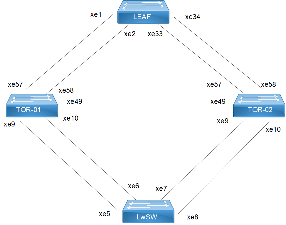
MLAG Active-Active Topology
LEAF
#configure terminal | Enter configure mode. |
(config)#hardware-profile filter egress-l2 enable | Enable the hardware-profile filter |
(config)#bridge 1 protocol rstp vlan-bridge | Create RSTP bridge 1. |
(config)#vlan 2 bridge 1 state enable | Create VLAN 2. |
(config)#interface po2 | Enter interface mode. |
(config-if)#switchport | Configure the interface as Layer 2 |
(config-if)#bridge-group 1 | Associate the interface with bridge group 1. |
(config-if)#switchport mode trunk | Set the switching characteristics of this interface to trunk mode. |
(config-if)#switchport trunk allowed vlan all | Enable all VLAN identifiers on this interface. |
(config-if)#commit | Commit the candidate configuration to the running configuration |
(config-if)#exit | Exit interface mode. |
(config)#interface xe1 | Enter interface mode. |
(config-if)#channel-group 2 mode active | Add this interface to channel group 2 and enable link aggregation so that it can be selected for aggregation by the local system. |
(config-if)#commit | Commit the candidate configuration to the running configuration |
(config-if)#exit | Exit interface mode. |
(config)#interface xe2 | Enter interface mode. |
(config-if)#channel-group 2 mode active | Add this interface to channel group 2 and enable link aggregation so that it can be selected for aggregation by the local system. |
(config-if)#commit | Commit the candidate configuration to the running configuration |
(config-if)#exit | Exit interface mode. |
(config)#interface xe33 | Enter interface mode. |
(config-if)#channel-group 2 mode active | Add this interface to channel group 2 and enable link aggregation so that it can be selected for aggregation by the local system. |
(config-if)#commit | Commit the candidate configuration to the running configuration |
(config-if)#exit | Exit interface mode. |
(config)#interface xe34 | Enter interface mode. |
(config-if)#channel-group 2 mode active | Add this interface to channel group 2 and enable link aggregation so that it can be selected for aggregation by the local system. |
(config-if)#commit | Commit the candidate configuration to the running configuration |
(config-if)#exit | Exit interface mode. |
LwSW
#configure terminal | Enter configure mode. |
(config)#hardware-profile filter egress-l2 enable | Enable the hardware-profile filter |
(config)#bridge 1 protocol rstp vlan-bridge | Create RSTP bridge 1. |
(config)#vlan 2 bridge 1 state enable | Create VLAN 2. |
(config)#interface po1 | Enter interface mode. |
(config-if)#switchport | Configure the interface as Layer 2 |
(config-if)#bridge-group 1 | Associate the interface with bridge group 1. |
(config-if)#switchport mode trunk | Set the switching characteristics of this interface to trunk mode. |
(config-if)#switchport trunk allowed vlan all | Enable all VLAN identifiers on this interface. |
(config-if)#commit | Commit the candidate configuration to the running configuration |
(config-if)#exit | Exit interface mode. |
(config)#interface xe5 | Enter interface mode. |
(config-if)#channel-group 1 mode active | Add this interface to channel group 1 and enable link aggregation so that it can be selected for aggregation by the local system. |
(config-if)#commit | Commit the candidate configuration to the running configuration |
(config-if)#exit | Exit interface mode. |
(config)#interface xe6 | Enter interface mode. |
(config-if)#channel-group 1 mode active | Add this interface to channel group 1 and enable link aggregation so that it can be selected for aggregation by the local system. |
(config-if)#commit | Commit the candidate configuration to the running configuration |
(config-if)#exit | Exit interface mode. |
(config)#interface xe7 | Enter interface mode. |
(config-if)#channel-group 1 mode active | Add this interface to channel group 1 and enable link aggregation so that it can be selected for aggregation by the local system. |
(config-if)#exit | Exit interface mode. |
(config)#interface xe8 | Enter interface mode. |
(config-if)#channel-group 1 mode active | Add this interface to channel group 1 and enable link aggregation so that it can be selected for aggregation by the local system. |
(config-if)#commit | Commit the candidate configuration to the running configuration |
(config-if)#exit | Exit interface mode. |
TOR-01
#configure terminal | Enter configure mode. |
(config)#hardware-profile filter egress-l2 enable | Enable the hardware-profile filter |
(config)#interface mlag1 | Enter interface mode. |
(config-if)#mode active-active | Mode need to be configured as active-active |
(config-if)#commit | Commit the candidate configuration to the running configuration |
(config-if)#exit | Exit interface mode. |
(config)#interface mlag2 | Enable the hardware-profile filter |
(config-if)#mode active-active | Mode need to be configured as active-active |
(config-if)#commit | Commit the candidate configuration to the running configuration |
(config-if)#exit | Exit interface mode. |
(config)#bridge 1 protocol rstp vlan-bridge | Create RSTP bridge 1. |
(config)#vlan 2 bridge 1 state enable | Create VLAN 2. |
(config)#interface mlag1 | Enter interface mode. |
(config-if)#switchport | Configure the interface as Layer 2 |
(config-if)#bridge-group 1 spanning-tree disable | Disable the spanning-tree for the interface |
(config-if)#switchport mode trunk | Set the switching characteristics of this interface to trunk mode. |
(config-if)#switchport trunk allowed vlan all | Enable all VLAN identifiers on this interface. |
(config-if)#commit | Commit the candidate configuration to the running configuration |
(config-if)#exit | Exit interface mode. |
(config)#interface mlag2 | Enter interface mode. |
(config-if)#switchport | Configure the interface as Layer 2 |
(config-if)#bridge-group 1 spanning-tree disable | Disable the spanning-tree for the interface |
(config-if)#switchport mode trunk | Set the switching characteristics of this interface to trunk mode. |
(config-if)#switchport trunk allowed vlan all | Enable all VLAN identifiers on this interface. |
(config-if)#commit | Commit the candidate configuration to the running configuration |
(config-if)#exit | Exit interface mode. |
(config)#interface po1 | Enter interface mode. |
(config-if)#switchport | Configure the interface as Layer 2 |
(config-if)#mlag 1 | Enabling MLAG group number |
(config-if)#commit | Commit the candidate configuration to the running configuration |
(config-if)#exit | Exit interface mode. |
(config)#interface po2 | Enter interface mode. |
(config-if)#switchport | Configure the interface as Layer 2 |
(config-if)#mlag 2 | enabling Mlag group number |
(config-if)#exit | Exit interface mode. |
(config)#interface xe9 | Enter interface mode. |
(config-if)#channel-group 1 mode active | Add this interface to channel group 1 and enable link aggregation so that it can be selected for aggregation by the local system. |
(config-if)#commit | Commit the candidate configuration to the running configuration |
(config-if)#exit | Exit interface mode. |
(config)#interface xe57 | Enter interface mode. |
(config-if)#channel-group 2 mode active | Add this interface to channel group 2 and enable link aggregation so that it can be selected for aggregation by the local system. |
(config-if)#commit | Commit the candidate configuration to the running configuration |
(config-if)#exit | Exit interface mode. |
(config)#interface xe58 | Enter interface mode. |
(config-if)#channel-group 2 mode active | Add this interface to channel group 2 and enable link aggregation so that it can be selected for aggregation by the local system. |
(config-if)#commit | Commit the candidate configuration to the running configuration |
(config-if)#exit | Exit interface mode. |
(config)#interface xe10 | Enter interface mode. |
(config-if)#channel-group 1 mode active | Add this interface to channel group 1 and enable link aggregation so that it can be selected for aggregation by the local system. |
(config-if)#commit | Commit the candidate configuration to the running configuration |
(config-if)#exit | Exit interface mode. |
(config)#interface xe49 | Enter interface mode. |
(config-if)#switchport | Configure the interface as Layer 2 |
(config-if)#exit | Exit interface mode. |
(config)#mcec domain configuration | Entering MCEC mode |
(config-mcec-domain)#domain-address 1111.2222.3333 | Domain address for the mlag domain |
(config-mcec-domain)#intra-domain link xe49 | Intra domain line between mlag domain |
(config-mcec-domain)#domain-system-number 1 | Number to identify the node in a domain |
(config-mcec-domain)#commit | Commit the candidate configuration to the running configuration |
(config-mcec-domain)#exit | Exit MCEC mode |
TOR-02
#configure terminal | Enter configure mode. |
(config)#hardware-profile filter egress-l2 enable | Enable the hardware-profile filter |
(config)#interface mlag1 | Enter interface mode. |
(config-if)#mode active-active | Mode need to be configured as active-active |
(config-if)#commit | Commit the candidate configuration to the running configuration |
(config-if)#exit | Exit interface mode |
(config)#interface mlag2 | Enable the hardware-profile filter |
(config-if)#mode active-active | Mode need to be configured as active-active |
(config-if)#commit | Commit the candidate configuration to the running configuration |
(config-if)#exit | Exit interface mode |
(config)#bridge 1 protocol rstp vlan-bridge | Create RSTP bridge 1. |
(config)#vlan 2 bridge 1 state enable | Create VLAN 2. |
(config)#interface mlag1 | Enter interface mode. |
(config-if)#switchport | Configure the interface as Layer 2 |
(config-if)#bridge-group 1 spanning-tree disable | Disable the spanning-tree for the interface |
(config-if)#switchport mode trunk | Set the switching characteristics of this interface to trunk mode. |
(config-if)#switchport trunk allowed vlan all | Enable all VLAN identifiers on this interface. |
(config-if)#commit | Commit the candidate configuration to the running configuration |
(config-if)#exit | Exit interface mode. |
(config)#interface mlag2 | Enter interface mode. |
(config-if)#switchport | Configure the interface as Layer 2 |
(config-if)#bridge-group 1 spanning-tree disable | Disable the spanning-tree for the interface |
(config-if)#switchport mode trunk | Set the switching characteristics of this interface to trunk mode. |
(config-if)#switchport trunk allowed vlan all | Enable all VLAN identifiers on this interface. |
(config-if)#commit | Commit the candidate configuration to the running configuration |
(config-if)#exit | Exit interface mode. |
(config)#interface po1 | Enter interface mode. |
(config-if)#switchport | Configure the interface as Layer 2 |
(config-if)#mlag 1 | Enabling Mlag group number |
(config-if)#commit | Commit the candidate configuration to the running configuration |
(config-if)#exit | Exit interface mode. |
(config)#interface po2 | Enter interface mode. |
(config-if)#switchport | Configure the interface as Layer 2 |
(config-if)#mlag 2 | enabling MLAG group number |
(config-if)#commit | Commit the candidate configuration to the running configuration |
(config-if)#exit | Exit interface mode. |
(config)#interface xe9 | Enter interface mode. |
(config-if)#channel-group 1 mode active | Add this interface to channel group 1 and enable link aggregation so that it can be selected for aggregation by the local system. |
(config-if)#commit | Commit the candidate configuration to the running configuration |
(config-if)#exit | Exit interface mode. |
(config)#interface xe10 | Enter interface mode. |
(config-if)#channel-group 1 mode active | Add this interface to channel group 1 and enable link aggregation so that it can be selected for aggregation by the local system. |
(config-if)#commit | Commit the candidate configuration to the running configuration |
(config-if)#exit | Exit interface mode. |
(config)#interface xe57 | Enter interface mode. |
(config-if)#channel-group 2 mode active | Add this interface to channel group 2 and enable link aggregation so that it can be selected for aggregation by the local system. |
(config-if)#commit | Commit the candidate configuration to the running configuration |
(config-if)#exit | Exit interface mode. |
(config)#interface xe58 | Enter interface mode. |
(config-if)#channel-group 2 mode active | Add this interface to channel group 2 and enable link aggregation so that it can be selected for aggregation by the local system. |
(config-if)#commit | Commit the candidate configuration to the running configuration |
(config-if)#exit | Exit interface mode. |
(config)#interface xe49 | Enter interface mode. |
(config-if)#switchport | Configure the interface as Layer 2 |
(config-if)#commit | Commit the candidate configuration to the running configuration |
(config-if)#exit | Exit interface mode. |
(config)#mcec domain configuration | Entering MCEC mode |
(config-mcec-domain)#domain-address 1111.2222.3333 | Domain address for the Mlag domain |
(config-mcec-domain)#intra-domain link xe49 | Intra domain Link between Mlag domains |
(config-mcec-domain)#domain-system-number 2 | Number to identify the node in domain |
(config-mcec-domain)#exit | Exit MCEC mode |
(config-mcec-domain)#commit | Commit the candidate configuration to the running configuration |
Validation
#sh mlag domain details
------------------------------------
Domain Configuration
------------------------------------
Domain System Number : 1
Domain Address : 1111.2222.3333
Domain Priority : 1000
Intra Domain Interface : xe49
Hello RCV State : Current
Hello Periodic Timer State : Fast Periodic
Domain Sync : IN_SYNC
Neigh Domain Sync : IN_SYNC
Domain Adjacency : UP
------------------------------------
MLAG Configuration
------------------------------------
MLAG-1
Mapped Aggregator : po1
Admin Key : 16385
Oper Key : 16385
Physical properties Digest : dd 9c f 76 dd b6 5f 2f eb a1 d3 bb 8d 96 fc 82
Neigh Admin Key : 32769
Neigh Physical Digest : dd 9c f 76 dd b6 5f 2f eb a1 d3 bb 8d 96 fc 82
Info RCV State : Current
Info Periodic Time State : Standby
Mlag Sync : IN_SYNC
Mode : Active-Active
Current Mlag State : Active
MLAG-2
Mapped Aggregator : po2
Admin Key : 16386
Oper Key : 16386
Physical properties Digest : dd 9c f 76 dd b6 5f 2f eb a1 d3 bb 8d 96 fc 82
Neigh Admin Key : 32770
Neigh Physical Digest : dd 9c f 76 dd b6 5f 2f eb a1 d3 bb 8d 96 fc 82
Info RCV State : Current
Info Periodic Time State : Standby
Mlag Sync : IN_SYNC
Mode : Active-Active
Current Mlag State : Active
#sh etherchannel summary
% Aggregator po1 0
% Aggregator Type: Layer2
% Admin Key: 16385 - Oper Key 16385
% Link: xe57 (5057) sync: 1 (Mlag-active-link)
% Link: xe58 (5058) sync: 1 (Mlag-active-link)
% Aggregator po2 0
% Aggregator Type: Layer2
% Admin Key: 16386 - Oper Key 16386
% Link: xe9 (5009) sync : 1 (Mlag-active-link)
% Link: xe10 (5010) sync: 1 (Mlag-active-link)
#sh mlag 1 detail
MLAG-1
Mapped Aggregator : po1
Admin Key : 16385
Oper Key : 16385
Physical properties Digest : dd 9c f 76 dd b6 5f 2f eb a1 d3 bb 8d 96 fc 82
Neigh Admin Key : 32769
Neigh Physical Digest : dd 9c f 76 dd b6 5f 2f eb a1 d3 bb 8d 96 fc 82
Info RCV State : Current
Info Periodic Time State : Standby
Total Bandwidth : 20g
Mlag Sync : IN_SYNC
Mode : Active-Active
Current Mlag State : Active
sh mcec statistics
Unknown MCCPDU received on the system : 0
------------------------------------
IDP xe49
------------------------------------
Valid RX Hello PDUs : 398
Valid TX Hello PDUs : 417
Valid RX Info PDUs : 16
Valid TX Info PDUs : 6
Valid RX Mac Sync PDUs : 3
Valid TX Mac Sync PDUs : 4
MLAG 1
Valid RX Info PDUs : 8
Valid TX Info PDUs : 3
MLAG 2
Valid RX Info PDUs : 8
Valid TX Info PDUs : 3
sh mlag domain summary
------------------------------------
Domain Configuration
------------------------------------
Domain System Number : 1
Domain Address : 1111.2222.3333
Domain Priority : 1000
Intra Domain Interface : xe49
Domain Adjacency : UP
------------------------------------
MLAG Configuration
------------------------------------
MLAG-1
Mapped Aggregator : po1
Physical properties Digest : dd 9c f 76 dd b6 5f 2f eb a1 d3 bb 8d 96 fc 82
Total Bandwidth : 40g
Mlag Sync : IN_SYNC
Mode : Active-Active
Current Mlag State : Active
MLAG-2
Mapped Aggregator : po2
Physical properties Digest : dd 9c f 76 dd b6 5f 2f eb a1 d3 bb 8d 96 fc 82
Total Bandwidth : 40g
Mlag Sync : IN_SYNC
Mode : Active-Active
Current Mlag State : Active
Static Configuration
Static MLAG provides node-level redundancy by allowing two or more nodes in the network to share a common static- LAG endpoint. It emulates multiple nodes to represent as a single logical node to the remote node having static Link aggregation. As a result, even if one of the nodes is down there exists a path to reach the destination via other nodes.
Topology
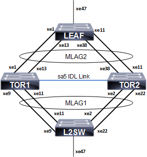
Static MLAG topology
L2SW
#configure terminal | Enter configure mode. |
(config)#hostname L2SW | Configuring host name |
(config)#bridge 1 protocol rstp vlan-bridge | Create a RSTP VLAN bridge on customer side |
(config)#vlan 2 bridge 1 state enable | Configure VLAN for the bridge |
(config)#interface sa1 | Enter the interface mode |
(config-if)#bridge-group 1 spanning-tree disable | Disable the spanning-tree for the interface |
(config-if)#switchport mode hybrid | Configure the mode as hybrid |
(config-if)#switchport hybrid allowed vlan all | Configure allowed VLAN all on the interface |
(config-if)#exit | Exit the interface mode |
(config)#interface xe2 | Enter the interface mode |
(config-if)#static-channel-group 1 | Map static channel to the interface |
(config-if)#exit | Exit the interface mode |
(config)#interface xe9 | Enter the interface mode |
(config-if)#static-channel-group 1 | Map static channel to the interface |
(config-if)#exit | Exit the interface mode |
(config)#interface xe11 | Enter the interface mode |
(config-if)#static-channel-group 1 | Map static channel to the interface |
(config-if)#exit | Exit the interface mode |
(config)#interface xe22 | Enter the interface mode |
(config-if)#static-channel-group 1 | Map static channel to the interface |
(config-if)#exit | Exit the interface mode |
(config)#interface xe47 | Enter the interface mode |
(config-if)#switchport | Make the interface as switch port |
(config-if)#bridge-group 1 spanning-tree disable | Disable the spanning-tree for the interface |
(config-if)#switchport mode hybrid | Configure the mode as hybrid |
(config-if)#switchport hybrid allowed vlan all | Configure allowed VLAN all on the interface |
(config-if)#exit | Exit the interface mode |
TOR1
#configure terminal | Enter configure mode. |
(config)#hostname TOR1 | Configuring host name |
(config)#bridge 1 protocol provider-rstp edge | Create a PROVIDER-RSTP EDGE bridge |
(config)#vlan 2 bridge 1 state enable | Configure VLAN for the bridge |
(config)#vlan 200 type service point-point bridge 1 state enable | Configure SVLAN for the bridge |
(config)#cvlan registration table map1 bridge 1 | Configure CVLAN-SVLAN mapping registration table for the bridge |
(config-cvlan-registration)#cvlan 2 svlan 200 | Map CVLAN to SVLAN |
(config-cvlan-registration)#exit | Exit the config-cvlan-registration mode |
(config)#interface mlag1 | Enter the interface mode |
(config-if)#switchport | Make the interface as switch port |
(config-if)#bridge-group 1 | Associate the interface to bridge |
(config-if)#switchport mode customer-edge hybrid | Configure the mode as customer-edge hybrid |
(config-if)#switchport customer-edge hybrid allowed vlan all | Configure allowed VLAN all on the interface |
(config-if)#switchport customer-edge vlan registration map1 | Map the CVLAN registration table into the MLAG interface |
(config-if)#mode active-standby | Configuring MLAG mode |
(config-if)#exit | Exit the interface mode |
(config)#interface mlag2 | Enter the interface mode |
(config-if)#switchport | Make the interface as switch port |
(config-.if)#bridge-group 1 | Associate the interface to bridge |
(config-if)#switchport mode provider- network | Configure the mode as provider-network |
(config-if)#switchport provider-network allowed vlan all | Configure allowed VLAN all on the interface |
(config-if)#mode active-standby | Configuring MLAG mode |
(config-if)#exit | Exit the interface mode |
(config)#interface sa1 | Enter the interface mode |
(config-if)#switchport | Make the interface as switch port |
(config-if)#mlag 1 | Map MLAG on SA interface |
(config-if)#exit | Exit the interface mode |
(config)#interface sa2 | Enter the interface mode |
(config-if)#switchport | Make the interface as switch port |
(config-if)#mlag 2 | Map MLAG on SA interface |
(config-if)#exit | Exit the interface mode |
(config)#interface xe1 | Enter the interface mode |
(config-if)#static-channel-group 2 | Map static channel-group to the interface |
(config-if)#exit | Exit the interface mode |
(config)#interface xe13 | Enter the interface mode |
(config-if)#static-channel-group 2 | Map static channel-group to the interface |
(config-if)#exit | Exit the interface mode |
(config)#interface xe9 | Enter the interface mode |
(config-if)#static-channel-group 1 | Map static channel-group to the interface |
(config-if)#exit | Exit the interface mode |
(config)#interface xe11 | Enter the interface mode |
(config-if)#static-channel-group 1 | Map static channel to the interface |
(config-if)#exit | Exit the interface mode |
(config)#interface sa5 | Enter the interface mode |
(config-if)#switchport | Make the interface as switch port |
(config-if)#exit | Exit the interface mode |
(config)#interface xe3 | Enter the interface mode |
(config-if)#static-channel-group 5 | Map static channel-group to the interface |
(config)#interface xe5 | Enter the interface mode |
(config-if)#static-channel-group 5 | Map static channel-group to the interface |
(config-if)#exit | Exit the interface mode |
(config)#mcec domain configuration | Enter the MLAG domain configuration mode |
(config-mcec-domain)#domain-address 1111.2222.3333 | Configure the MLAG domain address |
(config-mcec-domain)#domain-system-number 1 | Configure MLAG domain system number |
(config-mcec-domain)#intra-domain-link sa5 | Configure the intra domain link |
TOR2
#configure terminal | Enter configure mode. |
(config)#hostname TOR2 | Configuring host name |
(config)#bridge 1 protocol provider-rstp edge | Create a PROVIDER-RSTP EDGE bridge |
(config)#vlan 2 bridge 1 state enable | Configure VLAN for the bridge |
(config)#vlan 200 type service point-point bridge 1 state enable | Configure SVLAN for the bridge |
(config)#cvlan registration table map1 bridge 1 | Configure CVLAN-SVLAN mapping registration table for the bridge |
(config-cvlan-registration)#cvlan 2 svlan 200 | Map CVLAN to SVLAN |
(config-cvlan-registration)#exit | Exit the config-CVLAN-registration mode |
(config)#interface mlag1 | Enter the interface mode |
(config-if)#switchport | Make the interface as switch port |
(config-if)#bridge-group 1 | Associate the interface to bridge |
(config-if)#switchport mode customer-edge hybrid | Configure the mode as customer-edge hybrid |
(config-if)#switchport customer-edge hybrid allowed vlan all | Configure allowed VLAN all on the interface |
(config-if)#switchport customer-edge vlan registration map1 | Map the CVLAN registration table into the MLAG interface |
(config-if)#mode active-standby | Configuring MLAG mode |
(config-if)#exit | Exit the interface mode |
(config)#interface mlag2 | Enter the interface mode |
(config-if)#switchport | Make the interface as switch port |
(config-if)#bridge-group 1 | Associate the interface to bridge |
(config-if)#switchport mode provider- network | Configure the mode as provider-network |
(config-if)#switchport provider-network allowed vlan all | Configure allowed VLAN all on the interface |
(config-if)#mode active-standby | Configuring MLAG mode |
(config-if)#exit | Exit the interface mode |
(config)#interface sa1 | Enter the interface mode |
(config-if)#switchport | Make the interface as switch port |
(config-if)#mlag 1 | Map MLAG on SA interface |
(config-if)#exit | Exit the interface mode |
(config)#interface sa2 | Enter the interface mode |
(config-if)#switchport | Make the interface as switch port |
(config-if)#mlag 2 | Map MLAG on SA interface |
(config-if)#exit | Exit the interface mode |
(config)#interface xe11 | Enter the interface mode |
(config-if)#static-channel-group 2 | Map static channel to the interface |
(config-if)#exit | Exit the interface mode |
(config)#interface xe38 | Enter the interface mode |
(config-if)#static-channel-group 2 | Map static channel to the interface |
(config-if)#exit | Exit the interface mode |
(config)#interface xe2 | Enter the interface mode |
(config-if)#static-channel-group 1 | Create static channel group |
(config-if)#exit | Exit the interface mode |
(config)#interface xe22 | Enter the interface mode |
(config-if)#static-channel-group 1 | Create static channel group |
(config-if)#exit | Exit the interface mode |
(config)#interface sa5 | Enter the interface mode |
(config-if)#switchport | Make the interface as switch port |
(config-if)#exit | Exit the interface mode |
(config)#interface xe3 | Enter the interface mode |
(config-if)#static-channel-group 5 | Map static channel-group to the interface |
(config)#interface xe5 | Enter the interface mode |
(config-if)#static-channel-group 5 | Enter the interface mode |
(config-if)#exit | Exit the interface mode |
(config)#mcec domain configuration | Enter the MLAG domain configuration mode |
(config-mcec-domain)#domain-address 1111.2222.3333 | Configure the MLAG domain address |
(config-mcec-domain)#domain-system-number 2 | Configure MLAG domain system number |
(config-mcec-domain)#intra-domain-link sa5 | Configure the intra domain link |
(config-if)#exit | Exit the interface mode |
LEAF
#configure terminal | Enter configure mode. |
(config)#hostname LEAF | Configuring host name |
(config)#bridge 1 protocol provider-rstp edge | Create a PROVIDER-RSTP EDGE bridge |
(config)#vlan 2 bridge 1 state enable | Configure VLAN for the bridge |
(config)#vlan 200 type service point-point bridge 1 state enable | Configure SVLAN for the bridge |
(config)#cvlan registration table map1 bridge 1 | Configure CVLAN-SVLAN mapping registration table for the bridge |
(config-cvlan-registration)#cvlan 2 svlan 200 | Map CVLAN to SVLAN |
(config-cvlan-registration)#exit | Exit the config-CVLAN-registration mode |
(config)#interface sa2 | Enter the interface mode |
(config-if)#swtichport | Make the interface a switch port |
(config-if)#bridge-group 1 spanning-tree disable | Disable the spanning-tree for the interface |
(config-if)#switchport mode provider-network | Configure the mode as provider-network |
(config-if)#)#switchport provider-network allowed vlan all | Configure allowed VLAN all on the interface |
(config-if)#exit | Exit the interface mode |
(config)#interface xe1 | Enter the interface mode |
(config-if)#static-channel-group 2 | Map the interface to the static channel-group |
(config-if)#exit | Exit the interface mode |
(config)#interface xe13 | Enter the interface mode |
(config-if)#static-channel-group 2 | Create static channel group |
(config-if)#exit | Exit the interface mode |
(config)#interface xe11 | Enter the interface mode |
(config-if)#static-channel-group 2 | Map the interface to the static channel-group |
(config-if)#exit | Exit the interface mode |
(config)#interface xe38 | Enter the interface mode |
(config-if)#static-channel-group 2 | Create static channel group |
(config-if)#exit | Exit the interface mode |
(config)#interface xe47 | Enter the interface mode |
(config-if)#switchport | Make the interface as switch port |
(config-if)#bridge-group 1 spanning-tree disable | Disable the spanning-tree for the interface |
(config-if)#switchport mode customer-edge hybrid | Configure the mode as customer-edge hybrid |
(config-if)#switchport customer-edge hybrid allowed vlan all | Configure allowed VLAN all on the interface |
(config-if)#switchport customer-edge vlan registration map1 | Map the CVLAN registration table into the MLAG interface |
(config-if)#exit | Exit the interface mode |
Validation
TOR1#show mlag 1 detail
MLAG-1
Mapped Aggregator : sa1
Admin Key : 16385
Oper Key : 16385
Physical properties Digest : d a6 26 2d fa 9a 5c 7b e6 15 79 c2 d5 9c 57 cc
Neigh Admin Key : 32769
Neigh Physical Digest : d a6 26 2d fa 9a 5c 7b e6 15 79 c2 d5 9c 57 cc Info RCV State : Current
Info Periodic Time State : Standby Total Bandwidth : 40g
Mlag Sync : IN_SYNC
Mode : Active-Standby
Current Mlag State : Active
Switchover-mode : Revertive TOR1#
TOR1#show mlag domain summary
Domain Configuration
Domain
System Number :
1
Domain Address : 1111.2222.3333
Domain Priority : 32768
Intra Domain Interface : sa5
Domain Adjacency : UP
MLAG Configuration
MLAG-1
Mapped Aggregator : sa1
Physical properties Digest : d a6 26 2d fa 9a 5c 7b e6 15 79 c2 d5 9c 57 cc Total Bandwidth : 40g
Mlag Sync : IN_SYNC
Mode : Active-Standby
Current Mlag State : Active
Switchover-mode : Revertive
MLAG-2
Mapped Aggregator : sa2
Physical properties Digest : ae 56 a1 c5 b9 dc 46 a4 5d 97 dc 79 9c 6f a5 c8
Total Bandwidth : 40g
Mlag Sync : IN_SYNC
Mode : Active-Standby
Current Mlag State : Active
Switchover-mode : Revertive
TOR1#show mlag domain detail
Domain Configuration
Domain System Number : 1
Domain Address : 1111.2222.3333
Domain Priority : 32768
Intra Domain Interface : sa5
Hello RCV State : Current Hello Periodic Timer State : Slow Periodic Domain Sync : IN_SYNC
Neigh Domain Sync : IN_SYNC
Domain Adjacency : UP
MLAG Configuration
MLAG-1
Mapped Aggregator : sa1
Admin Key : 16385
Oper Key : 16385
Physical properties Digest : d a6 26 2d fa 9a 5c 7b e6 15 79 c2 d5 9c 57 cc
Neigh Admin Key : 32769
Neigh Physical Digest : d a6 26 2d fa 9a 5c 7b e6 15 79 c2 d5 9c 57 cc Info RCV State : Current
Info Periodic Time State : Standby Total Bandwidth : 40g
Mlag Sync : IN_SYNC
Mode : Active-Standby
Current Mlag State : Active Switchover-mode : Revertive
MLAG-2
Mapped Aggregator : sa2
Admin Key : 16386
Oper Key : 16386
Physical properties Digest : ae 56 a1 c5 b9 dc 46 a4 5d 97 dc 79 9c 6f a5 c8
Neigh Admin Key : 32770
Neigh Physical Digest : ae 56 a1 c5 b9 dc 46 a4 5d 97 dc 79 9c 6f a5 c8
Info RCV State : Current Info Periodic Time State : Standby Total Bandwidth : 40g
Mlag Sync : IN_SYNC
Mode : Active-Standby
Current Mlag State : Active Switchover-mode : Revertive
ARP ACL Configuration
Topology
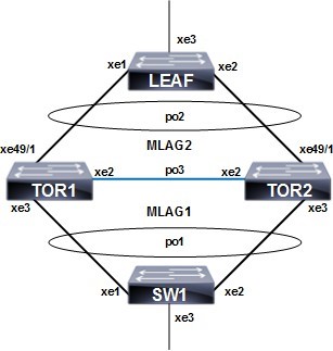
ARP ACL configuration with MC LAG
TOR1
#configure terminal | Enter configure mode. |
TOR1(config)#bridge 1 protocol provider-rstp edge | Create provider RSTP bridge |
TOR1(config)#vlan 2-3990 type customer bridge 1 state enable | Enable customer VLAN for bridge |
TOR1(config)#vlan 2-3990 type service point- point bridge 1 state enable | Enable service VLAN for bridge |
TOR1(config)#cvlan registration table map1 bridge 1 | Create registration table |
TOR1(config-cvlan-registration)#cvlan 2- 3990 svlan 3990 | Map CVLAN to svlan |
TOR1(config-cvlan-registration)#exit | Exit the CVLAN registration table mode |
TOR1(config-if)#interface mlag1 | Enter MLAG interface |
TOR1(config-if)#switchport | Configure interface as switchport |
TOR1(config-if)#exit | Exit the interface mode |
TOR1(config)#interface mlag2 | Enter MLAG interface |
TOR1(config-if)#switchport | Configure interface as switchport |
TOR1(config-if)#bridge-group 1 | Associate the interface with bridge group 1 |
TOR1(config-if)#switchport mode provider- network | Set the switching characteristics of this interface to provider network |
TOR1(config-if)#switchport provider-network allowed vlan all | Set the switching characteristics of this interface to provider network and allow all VLAN |
TOR1(config-if)#exit | Exit the interface mode |
TOR1(config)#interface po1 | Enter dynamic LAG interface |
TOR1(config-if)#switchport | Configure interface as switchport |
TOR1(config-if)#mlag 1 | Enable MLAG group number |
TOR1(config-if)#exit | Exit the interface mode |
TOR1(config-if)#interface po2 | Enter dynamic LAG interface |
TOR1(config-if)#switchport | Configure interface as switchport |
TOR1(config-if)#mlag 2 | Enable MLAG group number |
TOR1(config-if)#exit | Exit the interface mode |
TOR1(config)#interface po3 | Enter dynamic LAG interface |
TOR1(config-if)#switchport | Configure interface as switchport |
TOR1(config-if)#exit | Exit the interface mode |
TOR1(config)#interface xe2 | Enter interface mode |
TOR1(config-if)#channel-group 3 mode active | Make part of channel group 3 |
TOR1(config-if)#exit | Exit the interface mode |
TOR1(config)#interface xe3 | Enter interface mode |
TOR1(config-if)#channel-group 1 mode active | Add this interface to channel group 1 and enable link aggregation so that it can be selected for aggregation by the local system |
TOR1(config-if)#exit | Exit the interface mode |
TOR1(config-if)#interface xe49/1 | Enter interface mode |
TOR1(config-if)#channel-group 2 mode active | Enable channel-group 2 |
TOR1(config-if)#exit | Exit the interface mode |
TOR1(config)#mcec domain configuration | Enter MCEC mode |
TOR1(config-mcec-domain)#domain-address 2222.3333.4444 | Domain address for the MLAG domain |
TOR1(config-mcec-domain)#domain-system- number 1 | Number to identify the node in a domain |
TOR1(config-mcec-domain)#intra-domain-link po3 | Intra domain line between MLAG domain |
TOR1(config)#hardware-profile filter ingress-arp enable | Enable globally hardware profile for ARP |
TOR1(config)#arp access-list cep | Create access list with name as CEP |
TOR1(config-arp-acl)#30 permit request ip any mac host 0000.2A6C.668D vlan 3990 inner- vlan 2 | Create permit rule for particular ARP request |
TOR1(config-arp-acl)#40 permit response ip any any mac host 0000.2A6C.668D host 0000.2A6C.7202 vlan 3990 inner-vlan 2 | Create permit rule for particular ARP response |
TOR1(config)#arp access-list pnp | Create access list with name as PNP |
TOR1(config-arp-acl)#20 permit request ip any mac host 0000.2A6C.7202 vlan 3990 inner- vlan 2 | Create permit rule for particular ARP request |
TOR1(config-arp-acl)#30 permit response ip any any mac host 0000.2A6C.7202 host 0000.2A6C.668D vlan 3990 inner-vlan 2 | Create permit rule for particular ARP response |
TOR1(config-if)#interface mlag1 | Enter mlag1 interface |
TOR1(config-if)#arp access-group cep in | Attach rule with access-group CEP |
TOR1(config-if)#interface mlag2 | Enter mlag2 interface |
TOR1(config-if)#arp access-group pnp in | Attach rule with access-group PNP |
TOR2
#configure terminal | Enter configure mode. |
TOR2(config)#bridge 1 protocol provider-rstp edge | Create provider RSTP bridge |
TOR2(config)#vlan 2-3990 type customer bridge 1 state enable | Enable customer VLAN for bridge |
TOR2(config)#vlan 2-3990 type service point- point bridge 1 state enable | Enable service VLAN for bridge |
TOR2(config)#cvlan registration table map1 bridge 1 | Create registration table |
TOR2(config-cvlan-registration)#cvlan 2- 3990 svlan 3990 | Map CVLAN to svlan |
TOR2(config-cvlan-registration)#exit | Exit the CVLAN registration table mode |
TOR2(config)#interface mlag1 | Enter MLAG interface |
TOR2(config-if)#switchport | Configure interface as switchport |
TOR2(config-if)#bridge-group 1 spanning-tree disable | Associate the interface with bridge group 1and disabling spanning-tree |
TOR2(config-if)#switchport mode customer- edge hybrid | Set the switching characteristics of this interface to customer- edge hybrid |
TOR2(config-if)#switchport customer-edge hybrid allowed vlan all | Set the switching characteristics of this interface to customer- edge hybrid and allow VLAN all |
TOR2(config-if)#switchport customer-edge vlan registration map1 | Configure the registration table mapping on MLAG interface |
TOR2(config-if)#exit | Exit the interface mode |
TOR2(config)#interface mlag2 | Enter MLAG interface |
TOR2(config-if)#switchport | Configure interface as switchport |
TOR2(config-if)#bridge-group 1 | Associate the interface with bridge group 1 |
TOR2(config-if)#switchport mode provider- network | Set the switching characteristics of this interface to provider network |
TOR2(config-if)#switchport provider-network allowed vlan all | Set the switching characteristics of this interface to provider network and allow all VLAN |
TOR2(config-if)#exit | Exit the interface mode |
TOR2(config)#interface po1 | Enter dynamic LAG interface |
TOR2(config-if)#switchport | Configure interface as switchport |
TOR2(config-if)#mlag 1 | Enable MLAG group number |
TOR2(config-if)#exit | Exit the interface mode |
TOR2(config)#interface po2 | Enter dynamic LAG interface |
TOR2(config-if)#switchport | Configure interface as switchport |
TOR2(config-if)#mlag 2 | Enable MLAG group number |
TOR2(config-if)#exit | Exit the interface mode |
TOR2(config)#interface po3 | Enter dynamic LAG interface |
TOR2(config-if)#switchport | Configure interface as switchport |
TOR2(config-if)#exit | Exit the interface mode |
TOR2(config)#interface xe2 | Enter interface mode |
TOR2(config-if)#channel-group 3 mode active | Make part of channel group 3 |
TOR2(config-if)#interface xe3 | Enter interface mode |
TOR2(config-if)#channel-group 1 mode active | Add this interface to channel group 1 and enable link aggregation so that it can be selected for aggregation by the local system |
TOR2(config-if)#exit | Exit the interface mode |
TOR2(config)#Interface xe49/1 | Enter interface mode |
TOR2(config-if)#channel-group 2 mode active | Enable channel-group 2 |
TOR2(config)#mcec domain configuration | Configure MCEC domain information |
TOR2(config-mcec-domain)#domain-address 2222.3333.4444 | Domain address for the MLAG domain |
TOR2(config-mcec-domain)#domain-system- number 2 | Number to identify the node in a domain |
TOR2(config-mcec-domain)#intra-domain-link po3 | Intra domain line between MLAG domain |
TOR2(config)#hardware-profile filter ingress-arp enable | Enable globally hardware profile for ARP |
TOR2(config)#arp access-list cep | Create access list with name as CEP |
TOR2(config-arp-acl)#30 permit request ip any mac host 0000.2A6C.668D vlan 3990 inner- vlan 2 | Create permit rule for particular ARP request |
TOR2(config-arp-acl)#40 permit response ip any any mac host 0000.2A6C.668D host 0000.2A6C.7202 vlan 3990 inner-vlan 2 | Create permit rule for particular ARP response |
TOR2(config)#arp access-list pnp | Create access list with name as PNP |
TOR2(config-arp-acl)#20 permit request ip any mac host 0000.2A6C.7202 vlan 3990 inner- vlan 2 | Create permit rule for particular ARP request |
TOR2(config-arp-acl)#30 permit response ip any any mac host 0000.2A6C.7202 host 0000.2A6C.668D vlan 3990 inner-vlan 2 | Create permit rule for particular ARP response |
TOR2(config-if)#interface mlag1 | Enter mlag1 interface |
TOR2(config-if)#arp access-group cep in | Attach rule with access-group CEP |
TOR2(config-if)#interface mlag2 | Enter mlag2 interface |
TOR2(config-if)#arp access-group pnp in | Attach rule with access-group PNP |
SW1
#configure terminal | Enter configure mode. |
SW1(config)#bridge 1 protocol rstp vlan- bridge | Configure the RSTP VLAN bridge |
SW1(config)#vlan 2-3990 type customer bridge 1 state enable | Enable customer VLAN for bridge |
SW1(config-if)#interface po1 | Enter dynamic LAG interface |
SW1(config-if)#switchport | Configure interface as switchport |
SW1(config-if)#bridge-group 1 spanning-tree disable | Associate the interface with bridge group 1and disabling spanning-tree |
SW1(config-if)#switchport mode hybrid | Set the switching characteristics of this interface hybrid |
SW1(config-if)#switchport hybrid allowed vlan all | Set the switching characteristics of this interface hybrid and allowing all VLAN |
SW1(config-if)#exit | Exit the interface mode |
SW1(config)#interface xe1 | Enter interface mode |
SW1(config-if)#channel-group 1 mode active | Add this interface to channel group 1 and enable link aggregation so that it can be selected for aggregation by the local system. |
SW1(config-if)#exit | Exit the interface mode |
SW1(config)#interface xe2 | Enter interface mode |
SW1(config-if)#channel-group 1 mode active | Add this interface to channel group 1 and enable link aggregation so that it can be selected for aggregation by the local system. |
SW1(config-if)#exit | Exit the interface mode |
SW1(config)#interface xe3 | Enter interface mode |
SW1(config-if)#switchport | Configure interface as switchport |
SW1(config-if)#bridge-group 1 spanning-tree disable | Associate the interface with bridge group 1and disabling spanning-tree |
SW1(config-if)#switchport mode hybrid | Set the switching characteristics of this interface hybrid |
SW1(config-if)#switchport hybrid allowed vlan all | Set the switching characteristics of this interface hybrid and allowing all VLAN |
SW1(config-if)#exit | Exit the interface mode |
LEAF
#configure terminal | Enter configure mode. |
Leaf(config)#bridge 1 protocol provider-rstp edge | Configure the RSTP VLAN bridge |
Leaf(config)#vlan 2-3990 type customer bridge 1 state enable | Enable customer VLAN for bridge |
Leaf(config)#vlan 2-3990 type service point- point bridge 1 state enable | Enable service VLAN for bridge |
Leaf(config)#cvlan registration table map1 bridge 1 | Create registration table |
Leaf(config-cvlan-registration)#cvlan 2- 3990 svlan 3990 | Map CVLAN to SVLAN |
Leaf(config-if)#exit | Exit the CVLAN registration table mode |
Leaf(config)#interface po2 | Enter interface mode |
Leaf(config-if)#switchport | Configure interface as switchport |
Leaf(config-if)#bridge-group 1 spanning-tree disable | Associate the interface with bridge group 1and disabling spanning-tree |
Leaf(config-if)#switchport mode provider- network | Set the switching characteristics of this interface provider network |
Leaf(config-if)#switchport provider-network allowed vlan all | Set the switching characteristics of this interface provider and allowing all VLAN |
Leaf(config-if)#exit | Exit the interface mode |
Leaf(config)#interface xe1 | Enter interface mode |
Leaf(config-if)#channel-group 2 mode active | Add this interface to channel group 2 and enable link aggregation so that it can be selected for aggregation by the local system. |
Leaf(config-if)#exit | Exit the interface mode |
Leaf(config)#interface xe2 | Enter interface mode |
Leaf(config-if)#channel-group 2 mode active | Add this interface to channel group 2 and enable link aggregation so that it can be selected for aggregation by the local system. |
Leaf(config-if)#exit | Exit the interface mode |
Leaf(config)#Interface xe3 | Enter interface mode |
Leaf(config-if)#switchport | Configure interface as switchport |
Leaf(config-if)#bridge-group 1 spanning-tree disable | Associate the interface with bridge group 1and disabling spanning-tree |
Leaf(config-if)#switchport mode customer- edge hybrid | Set the switching characteristics of this interface to customer- edge hybrid |
Leaf(config-if)#switchport customer-edge hybrid allowed vlan all | Set the switching characteristics of this interface to customer- edge hybrid and allow vlan all |
Leaf(config-if)#switchport customer-edge vlan registration map1 | Configure the registration table mapping on mlag interface |
Leaf(config-if)#exit | Exit the interface mode |
Validation
TOR1#show access-lists
ARP access list cep
30 permit request ip any mac host 0000.2A6C.668D vlan 3990 inner-vlan 2
40 permit response ip any any mac host 0000.2A6C.668D host 0000.2A6C.7202 vlan 3990 inner-vlan 2
default deny-all ARP access list pnp
20 permit request ip any mac host 0000.2A6C.7202 vlan 3990 inner-vlan 2 [match=1]
30 permit response ip any any mac host 0000.2A6C.7202 host 0000.2A6C.668D vlan 3990 inner-vlan 2 [match=1]
default deny-all log
TOR2#show access-lists
ARP access list cep
30 permit request ip any mac host 0000.2A6C.668D vlan 3990 inner-vlan 2 [match=1]
40 permit response ip any any mac host 0000.2A6C.668D host 0000.2A6C.7202 vlan 3990 inner-vlan 2 [match=1]
default deny-all log ARP access list pnp
20 permit request ip any mac host 0000.2A6C.7202 vlan 3990 inner-vlan 2
30 permit response ip any any mac host 0000.2A6C.7202 host 0000.2A6C.668D vlan 3990 inner-vlan 2
default deny-all