Hybrid Switch Router Configuration
This chapter describes configurations that can be done with the Hybrid Switch Router solution. OcNOS can be configured as a Layer 2 switch, a Layer 3 router or a Hybrid Switch Router.
Overview
An OcNOS Hybrid Switch Router offers Layer 3 forwarding found in routers with the high-speed performance associated with traditional Layer 2 switches. The following are some advantages of Hybrid Switch Routers:
• Reduced system cost and infrastructure. Traditionally you would require a separate box for switching and one for routing.
• Off-loading IP traffic from backbone routers, thus making them more efficient for firewalls and WAN connectivity.
• Simplified network design and maintenance.
Routing and Switching
Layer 2 and Layer 3 switches are similar at a high-level, both look at the packet headers, and steer the packets toward their destination port. Therefore, after being passed through a switch or router, the packet is closer to its destination.
Layer 2 Switching
Layer 2 switches are typically used to provide connectivity within high bandwidth local area networks (LANs). A Layer 2 switch makes forwarding decisions based on the MAC or the Layer 2 header. It extracts the Layer 2 header from the packet, finds a matching destination address in the forwarding table, and transmits the packet out to the port associated with the specific destination address in the forwarding table. The forwarding table is populated through a self-learning process, whereby each arriving packet is used to update the entries in the table. Typically, the Layer 2 switch implements the switching function in the hardware, as that requires stripping of the packet only in two layers (the physical and data link layer) to get to the useful part of the packet header. This allows switches to steer packets at wire-speed rates without slowing down arriving streams of packets to process them.
Layer 3 Routing
Layer 3 (L3) routers are typically used to provide connectivity between different LANs. A Layer 3 router discards MAC headers, and indexes further into the packet–making decisions based on the IP or Layer 3 header. It extracts the Layer‑3 header from the packet, finds a matching destination address in a routing table, identifies a new MAC address for the packet from an ARP cache, wraps the IP packet in a new MAC header, and then transmits the packet out to the port associated with that destination address in the routing table.
The routing table is populated through statically configured command line interface entries or through routing protocol messages from neighboring routers. A Layer 3 router must strip through 3 layers (physical, data link, and network) which is more complicated than a Layer 2 switch. Layer 3 routers historically implement the routing function in software. This often results in limited packet-forwarding rates. However, improvements in VLSI circuit technology have allowed Layer 3 routing functions to be implemented rapidly in hardware, enabling wire-speed performance similar to the performance of Layer 2 switches. As a result, along with the complexity of next-generation Layer 3 routers, the throughput of these routers has also been increasing.
An architecture is required that is flexible enough to accommodate the demands of different customers, and accommodate the changing demands of a single customer whose requirements may change over time. Typical Layer 2 switches and Layer 3 routers fail to provide this flexibility.
An optimal configuration can be an integrated solution, a Layer 3 router with Layer 2 bridge groups around it. The OcNOS Hybrid Switch Router implementation allows easy configuration of different combinations of routers and switches. OcNOS can be configured as an absolute Layer 3 router, absolute Layer 2 switch (Figure 8-9) or a hybrid Layer 2/Layer 3 switch router, (Figure 8-10) that can easily change modes with the use of a single command.
System Configuration
• OcNOS stack will bring up all the ports of the board as routed ports by default.
• However OcNOS provides flexibility to create a Layer 2 bridge, and ports can be converted to switch ports and added to the bridge.
• OcNOS also supports VLAN interfaces and routing between VLANs.
Thus it can work as a router, a switch, or as a hybrid switch.
Hybrid Switch Router Possibilities
With only Layer 2 protocols configured, the OcNOS Hybrid Switch Router can become an absolute Layer 2 switch.
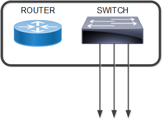
Layer 2 Switch
With Layer 2 and Layer 3 protocols configured, the OcNOS Hybrid Switch Router can become a Switch and/or a Router.
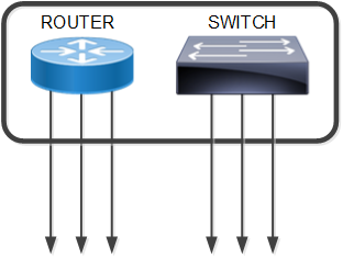
Working as a Router or a Switch
With only Layer 3 protocols enabled, the OcNOS Hybrid Switch Router can become an absolute router.
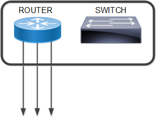
Working as Layer 3 Router
On switch ports, VLANs can be created for different broadcast domains.
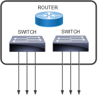
Port- or Policy-based VLANs
For routing between VLANs, the OcNOS routing protocols or static routing via NSM can be utilized.
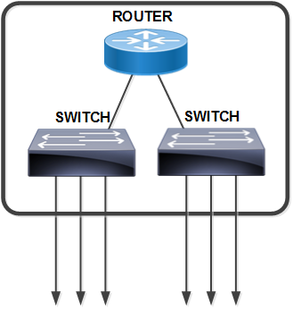
Routing between VLANs
For routing between VLANs and other routing ports, OcNOS routing protocols or static routing via NSM can be utilized.
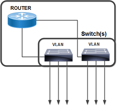
Routing between VLANs and Routing Ports
Configuring Layer 2 Interfaces
For the Hybrid Switch Router, it is important to understand that by default, all interfaces are configured as routed interfaces. To configure a Layer 2 interface (switched interface), you must explicitly configure this using the switchport command in the interface mode. For example:
#configure terminal | Enter the Configure mode. |
(config)#bridge 1 protocol mstp | Create a MSTP bridge. |
(config)#interface eth2 | Specify an interface to configure and enter the Interface mode. |
(config-if)#switchport | Configure eth2 as a Layer 2 port. |
(config-if)#bridge-group 1 | Associate interface to bridge 1. |
(config-if)#no shutdown | Start interface.eth2 |
(config-if)#commit | Commit the candidate configuration to the running configuration |
(config-if)#exit | Exit interface mode |
Configuring Layer 3 Interfaces
For the Hybrid Switch Router, it is important to understand that by default, all interfaces in OcNOS are L3 ports. If a port has been configured as L2, then use the no switchport command to make it a L3 port.
For example:
#configure terminal | Enter the Configure mode. |
(config)#interface eth3 | Specify an interface to configure and enter the Interface mode. |
(config-if)#no switchport | Configure eth3 as a Layer 3 port. |
(config-if)#commit | Commit the candidate configuration to the running configuration |
(config-if)#exit | Exit interface mode |
In the Hybrid Switch Router mode, if a VLAN is configured, a Layer 3 interface based on the bridge-group number and VLAN ID is created. This Layer 3 interface is advertised to all the Layer 3 protocols. For example:
#configure terminal | Enter the Configure mode. |
(config)#bridge 1 protocol mstp | Creating bridge. |
(config)#vlan database | Enter the VLAN configure mode. |
(config-vlan)#vlan 2 bridge 1 | Enable VLAN 2 on bridge 1. |
(config-vlan)#commit | Commit the candidate configuration to the running configuration |
(config-vlan)#exit | Exit VLAN configure mode |
The last step in the example above show an interface given a name with the following format:
vlanXX.YYYY
Where XX is the bridge ID, and YYYY is the VLAN ID,
For example, the name, vlan1.3 indicates that VLAN IP’s interface is in VLAN 3, and bridge-group 1.