Multi-Area Redundant Adjacency Configuration
Overview
The Open Shortest Path First (OSPFv2) is an Interior Gateway Protocol (IGP) that uses a link-state methodology, which calculates the distance among the routers (to determine the link cost) in the network and then distributes the routing information to other routers belonging to a single Autonomous System.
In a link-state routing protocol, each participating router in a network maintains an identical database using the same Autonomous System's topology. Each router's database indicates the local state to other routers. It treats itself as a root and constructs a shortest routing path. This path gives a route for each destination in the Autonomous System.
In this protocol, the entire network is divided into sub-domains. Each sub-domain is referred as 'Area'. One of the sub-domains is classified as ‘Area 0‘ which is the ‘Backbone Area’; rest of the Areas are referred as 'Regular Area” or “Non Zero Area”. The routing among the ‘Regular Area’ is via the ‘Backbone Area’ only even though the cost link is high. A node with one ‘Area 0’ and multiple ‘Regular Area’ is named Area Border Router (ABR).
Enabling one or more ‘Regular areas’ to have Multi-Area over an interface that is part of the ‘Backbone Area’, enhances the routing capability to choose more routing paths as against the regular routing path, irrespective of high link cost. This enhances the routing communications from a ‘Regular Area’ to a ‘Regular Area’ in another ABR via ‘Backbone Area’.
This functionality is enhanced to support the Multi-Area over multiple interfaces of the ‘Backbone Area’.
For more information, refer to https://datatracker.ietf.org/doc/html/rfc5185.
Feature Characteristics
Supports Multi-Area redundancy configuration in multiple interfaces of the ‘Backbone Area’ (aka 'Area 0') for the same 'Regular Area'.
After configuring Multi-Area redundancy, the router provides redundancy paths to reach other networks from the ‘Regular Area’ via ‘Backbone Area’.
The Multi-Area redundancy configuration works only when Multi-Area neighbor is specified using ip ospf <id> multi-area <area-id> neighbor <neighbor-ip> command.
LIMITATION:
• It is mandatory to specify the neighbor ip address to configure Multi-Area redundancy in more than one interface of ‘Area 0’.
• Only IPv4 support is provided;.
• Configuring more than one Multi-Area in a interface for the same ‘Area 0’ is not supported
• OSPF neighborship should exists to form Multi-Area adjacency
• Multi-Area adjacency is formed between ABR’s.
Benefits
Provides flexibility to use multiple interfaces of Area 0 to reach the Regular Area in different network. Hence, when one of the interfaces goes down the other interface is used to reach the destination.
Prerequisites
The router must be configured with OSPFv2 with Multi-Area support. For more information, refer to Multi-Area Adjacency Configuration.
Configuration
The following configuration enables the Multi-Area feature on multiple interfaces in the OcNOS devices.
Topology
The following scenario illustrates a Regular Area 99 configured between R1-R4, R4-R3, R3-R2 and R2-R5.
The default routing communication between R1 to R3 is using the Multi-Area 99 via R1-R4-R3 even though the link cost between R4-R3 is high.
Figure 2-65 illustrates the Multi-Area Adjacency routing information.
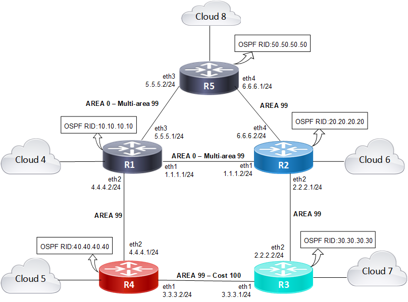
OSPFv2 Multi-Area Adjacency with Multiple Interfaces
The Multi-Area support changes this default behavior and permits that once Multi-Area is enabled on eth1 Area 0 for Multi-Area 99 in R1, the routing communication between R1 and R3 is via R1-R2-R3 as eth1 Area 99 link cost is high.
Enabling Multi-Area in multiple interfaces, for example on eth1 and eth3 of Area 0 with Multi-Area 99, provides redundancy when eth1 Area 0 goes down. Hence, the routing communication between R1 and R3 occurs via R1-R5-R2-R3.
Perform the following steps to configure the Multi-Area Adjacency on OcNOS devices:
1. Configure the OSPFv2 router’s source interfaces IP address, network type, Multi-Area information and OSPF cost of the link on R1, R2, R3, R4, and R5 using the following sample configurations:
R1 source interfaces eth1, eth2, eth3
(config)#interface eth1
(config-if)#ip address 1.1.1.1/24
(config-if)#ip ospf network point-to-point
(config-if)#ip ospf 0 multi-area 99
(config-if)#ip ospf network point-to-point
(config-if)#ip ospf 0 multi-area 99
(config-if)#interface eth2
(config-if)#ip address 4.4.4.2/24
(config-if)#ip ospf network point-to-point
(config-if)#interface eth3
(config-if)#ip address 5.5.5.1/24
(config-if)#ip ospf network point-to-point
(config-if)#ip ospf 0 multi-area 99 neighbor 5.5.5.2
(config-if)#ip ospf network point-to-point
(config-if)#ip ospf 0 multi-area 99 neighbor 5.5.5.2
R2 source interfaces eth1, eth2, eth4
(config-if)#interface eth2
(config-if)#ip address 2.2.2.1/24
(config-if)#ip ospf network point-to-point
(config)#interface eth1
(config-if)#ip address 1.1.1.2/24
(config-if)#ip ospf network point-to-point
(config-if)#ip ospf 0 multi-area 99
(config-if)#interface eth4
(config-if)#ip address 6.6.6.2/24
(config-if)#ip ospf network point-to-point
R3 source interfaces eth1, eth2
(config)#interface eth1
R3 source interfaces eth1, eth2
(config)#interface eth1
(config-if)#ip address 3.3.3.1/24
(config-if)#ip ospf network point-to-point
(config-if)#ip ospf cost 100
(config)#interface eth2
(config-if)#ip address 2.2.2.2/24
(config-if)#ip ospf network point-to-point
R4 source interfaces eth1, eth2
(config)#interface eth1
(config-if)#ip address 3.3.3.2/24
(config-if)#ip ospf network point-to-point
(config-if)#ip ospf cost
(config)#interface eth2
(config-if)#ip address 4.4.4.1/24
(config-if)#ip ospf network point-to-point
R5 source interfaces eth3, eth4
(config)#interface eth3
(config-if)#ip address 5.5.5.2/24
(config-if)#ip ospf network point-to-point
(config-if)#ip ospf 0 multi-area 0.0.0.99
(config-if)#interface eth4
(config-if)#ip address 6.6.6.1/24
(config-if)#ip ospf network point-to-point
2. Configure an OSPF instance with an instance ID on R1, R2, R3, R4, and R5. Refer to theTopology diagram for the router ID.
(config)#router ospf
(config-router)# ospf router-id 10.10.10.10
(config-router)# ospf router-id 10.10.10.10
3. Configure OSPF routing with Multi-Area area 0 /area 99 area ID and assign loopback IP address to R1, R2, R3, R4 and R5.
R1 - between R1 - R2, R1 - R4, and R1 - R5
R1 - between R1 - R2, R1 - R4, and R1 - R5
(config-router)#network 1.1.1.0/24 area 0.0.0.0
(config-router)#network 4.4.4.0/24 area 0.0.0.99
(config-router)#network 5.5.5.0/24 area 0.0.0.0
(config-router)#network 10.10.10.10/32 area 0.0.0.0
R2 - between R1 - R2, R2 - R3, and R2 - R4
(config-router)#network 1.1.1.0/24 area 0.0.0.0
(config-router)#network 2.2.2.0 /24 area 0.0.0.99
(config-router)#network 6.6.6.0/24 area 0.0.0.99
(config-router)#network 20.20.20.20/32 area 0.0.0.99
R3 - between R2 - R3, and R3 - R4
(config-router)#network 2.2.2.0/24 0.0.0.99
R3 - between R2 - R3, and R3 - R4
(config-router)#network 2.2.2.0/24 0.0.0.99
(config-router)#network 3.3.3.0/24 area 0.0.0.99
(config-router)#network 30.30.30.30/32 area 0.0.0.99
R4 - between R3 - R4, and R1 - R4.
(config-router)#network 3.3.3.0/24 area 0.0.0.99
(config-router)#network 4.4.4.0/24 area 0.0.0.99
(config-router)#network 40.40.40.40/32 area 0.0.0.99
R5 - between R1 - R5, and R2 - R5.
R5 - between R1 - R5, and R2 - R5.
(config-router)#network 5.5.5.0/24 area 0.0.0.0
(config-router)#network 6.6.6.0/24 area 0.0.0.99
(config-router)#network 50.50.50.50/32 area 0.0.0.99
Sample show running-config Output
R1
!
interface eth1
ip address 1.1.1.1/24
ip ospf network point-to-point
ip ospf 0 multi-area 0.0.0.99
!
interface eth2
ip address 4.4.4.2/24
ip ospf network point-to-point
!
interface eth3
ip address 5.5.5.1/24
ip ospf network point-to-point
ip ospf 0 multi-area 0.0.0.99 neighbor 5.5.5.2
!
!
router ospf
ospf router-id 10.10.10.10
network 1.1.1.0/24 area 0.0.0.0
network 4.4.4.0/24 area 0.0.0.99
network 5.5.5.0/24 area 0.0.0.0
network 10.10.10.10/32 area 0.0.0.0
!
!
R2
!
interface eth1
ip address 1.1.1.2/24
ip ospf network point-to-point
ip ospf 0 multi-area 0.0.0.99
!
interface eth2
ip address 2.2.2.1/24
ip ospf network point-to-point
!
interface eth3
!
interface eth4
ip address 6.6.6.2/24
ip ospf network point-to-point
!
router ospf
ospf router-id 20.20.20.20
network 1.1.1.0/24 area 0.0.0.0
network 2.2.2.0/24 area 0.0.0.99
network 6.6.6.0/24 area 0.0.0.99
network 20.20.20.20/32 area 0.0.0.99
!
R3
!
interface eth1
ip address 3.3.3.1/24
ip ospf network point-to-point
ip ospf cost 250
!
interface eth2
ip address 2.2.2.2/24
ip ospf network point-to-point
!
!
router ospf
ospf router-id 30.30.30.30
network 2.2.2.0/24 area 0.0.0.99
network 3.3.3.0/24 area 0.0.0.99
network 30.30.30.30/32 area 0.0.0.99
!
R4
!
interface eth1
ip address 3.3.3.2/24
ip ospf network point-to-point
ip ospf cost 250
!
interface eth2
ip address 4.4.4.1/24
ip ospf network point-to-point
!
router ospf
ospf router-id 40.40.40.40
network 3.3.3.0/24 area 0.0.0.99
network 4.4.4.0/24 area 0.0.0.99
network 40.40.40.40/32 area 0.0.0.99
!
ip route 20.1.1.0/24 10.1.1.1
!
!
R5
!
interface eth3
ip address 5.5.5.2/24
ip ospf network point-to-point
ip ospf 0 multi-area 0.0.0.99
!
interface eth4
ip address 6.6.6.1/24
ip ospf network point-to-point
!
!
router ospf
ospf router-id 50.50.50.50
network 5.5.5.0/24 area 0.0.0.0
network 6.6.6.0/24 area 0.0.0.99
network 50.50.50.50/32 area 0.0.0.99
!
Validation
R1
The following show output displays the Multi-Area Adjacency information for OSPF router.
OcNOS#show ip ospf multi-area-adjacencies
Multi-area-adjacency link on interface eth1 to neighbor 1.1.1.2
Internet Address 1.1.1.1/24, Area 0.0.0.99, MTU 1500
Process ID 0, Router ID 10.10.10.10, Network Type POINT_TO_POINT, Cost: 1
Transmit Delay is 1 sec, State Point-To-Point, TE Metric 1
Timer intervals configured, Hello 10, Dead 40, Wait 40, Retransmit 5
Hello due in 00:00:01
Neighbor Count is 1, Adjacent neighbor count is 1
Hello received 700 sent 743, DD received 3 sent 4
LS-Req received 0 sent 0, LS-Upd received 53 sent 80
LS-Ack received 50 sent 25, Discarded 0
Multi-area-adjacency link on interface eth3 to neighbor 5.5.5.2
Internet Address 5.5.5.1/24, Area 0.0.0.99, MTU 1500
Process ID 0, Router ID 10.10.10.10, Network Type POINT_TO_POINT, Cost: 1
Transmit Delay is 1 sec, State Point-To-Point, TE Metric 1
Timer intervals configured, Hello 10, Dead 40, Wait 40, Retransmit 5
Hello due in 00:00:07
Neighbor Count is 1, Adjacent neighbor count is 1
Hello received 684 sent 735, DD received 3 sent 4
LS-Req received 1 sent 1, LS-Upd received 31 sent 79
LS-Ack received 70 sent 23, Discarded 0
OcNOS#
The following show output displays the neighbor IP address of the R1.
OcNOS#show ip ospf neighbor
Total number of full neighbors: 5
OSPF process 0 VRF(default):
Neighbor ID Pri State Dead Time Address Interface Instance ID
20.20.20.20 1 Full/ - 00:00:32 1.1.1 eth1 0
40.40.40.40 1 Full/ - 00:00:29 4.4.4.1 eth2 0
50.50.50.50 1 Full/ - 00:00:39 5.5.5.2 eth3 0
20.20.20.20 1 Full/ - 00:00:36 1.1.1.2 eth1
50.50.50.50 1 Full/ - 00:00:37 5.5.5.2 eth3
OcNOS#
The following show output displays the OSPF routing information of the R1.
OcNOS#show ip ospf route
OSPF process 0:
Codes: C - connected, D - Discard, O - OSPF, IA - OSPF inter area
N1 - OSPF NSSA external type 1, N2 - OSPF NSSA external type 2
E1 - OSPF external type 1, E2 - OSPF external type 2
OSPF LFA attributes:
P - Primary, SP - Secondary-Path, LP - Link Protecting,
NP - Node Protecting, BID - Broadcast Link Protecting
DP - Downstream Protecting
C 1.1.1.0/24 [1] is directly connected, eth1, Area 0.0.0.0
O 2.2.2.0/24 [2] via 1.1.1.2, eth1, Area 0.0.0.99
O 3.3.3.0/24 [101] via 4.4.4.1, eth2, Area 0.0.0.99
C 4.4.4.0/24 [1] is directly connected, eth2, Area 0.0.0.99
C 5.5.5.0/24 [1] is directly connected, eth3, Area 0.0.0.0
O 6.6.6.0/24 [2] via 1.1.1.2, eth1, Area 0.0.0.99
via 5.5.5.2, eth3, Area 0.0.0.99
C 10.10.10.10/32 [1] is directly connected, lo, Area 0.0.0.0
O 20.20.20.20/32 [2] via 1.1.1.2, eth1, Area 0.0.0.99
O 30.30.30.30/32 [3] via 1.1.1.2, eth1, Area 0.0.0.99
O 40.40.40.40/32 [2] via 4.4.4.1, eth2, Area 0.0.0.99
O 50.50.50.50/32 [2] via 5.5.5.2, eth3, Area 0.0.0.99
OcNOS#
The following show output displays the IP route information of the R1.
OcNOS#show ip route
Codes: K - kernel, C - connected, S - static, R - RIP, B - BGP
O - OSPF, IA - OSPF inter area
N1 - OSPF NSSA external type 1, N2 - OSPF NSSA external type 2
E1 - OSPF external type 1, E2 - OSPF external type 2
i - IS-IS, L1 - IS-IS level-1, L2 - IS-IS level-2,
ia - IS-IS inter area, E - EVPN,
v - vrf leaked
* - candidate default
IP Route Table for VRF "default"
Gateway of last resort is 10.12.100.1 to network 0.0.0.0
K* 0.0.0.0/0 [0/0] via 10.12.100.1, eth0
C 1.1.1.0/24 is directly connected, eth1, 01:54:16
O 2.2.2.0/24 [110/2] via 1.1.1.2, eth1, 01:23:42
O 3.3.3.0/24 [110/101] via 4.4.4.1, eth2, 00:11:12
C 4.4.4.0/24 is directly connected, eth2, 5d09h32m
C 5.5.5.0/24 is directly connected, eth3, 5d09h39m
O 6.6.6.0/24 [110/2] via 5.5.5.2, eth3, 01:23:57
[110/2] via 1.1.1.2, eth1
C 10.10.10.10/32 is directly connected, lo, 00:32:27
C 10.12.100.0/22 is directly connected, eth0, 03w1d02h
O 20.20.20.20/32 [110/2] via 1.1.1.2, eth1, 00:27:24
O 30.30.30.30/32 [110/3] via 1.1.1.2, eth1, 00:21:38
O 40.40.40.40/32 [110/2] via 4.4.4.1, eth2, 00:17:09
O 50.50.50.50/32 [110/2] via 5.5.5.2, eth3, 00:04:53
C 127.0.0.0/8 is directly connected, lo, 03w1d02h
OcNOS#
R2
The following show output displays the Multi-Area Adjacency information for OSPF router.
OcNOS#show ip ospf multi-area-adjacencies
Multi-area-adjacency link on interface eth1 to neighbor 1.1.1.1
Internet Address 1.1.1.2/24, Area 0.0.0.99, MTU 1500
Process ID 0, Router ID 20.20.20.20, Network Type POINT_TO_POINT, Cost: 1
Transmit Delay is 1 sec, State Point-To-Point, TE Metric 1
Timer intervals configured, Hello 10, Dead 40, Wait 40, Retransmit 5
Hello due in 00:00:00
Neighbor Count is 1, Adjacent neighbor count is 1
Hello received 726 sent 727, DD received 4 sent 3
LS-Req received 0 sent 0, LS-Upd received 85 sent 56
LS-Ack received 25 sent 52, Discarded 0
OcNOS#
The following show output displays the neighbor IP address of the R2.
OcNOS#show ip ospf neighbor
Total number of full neighbors: 4
OSPF process 0 VRF(default):
Neighbor ID Pri State Dead Time Address Interface Instance ID
10.10.10.10 1 Full/ - 00:00:33 1.1.1.1 eth1 0
30.30.30.30 1 Full/ - 00:00:29 2.2.2.2 eth2 0
50.50.50.50 1 Full/ - 00:00:32 6.6.6.1 eth4 0
10.10.10.10 1 Full/ - 00:00:35 1.1.1.1 eth1 0
OcNOS#
The following show output displays the OSPF Multi-Area routing information of the R1.
OcNOS#show ip ospf route
OSPF process 0:
Codes: C - connected, D - Discard, O - OSPF, IA - OSPF inter area
N1 - OSPF NSSA external type 1, N2 - OSPF NSSA external type 2
E1 - OSPF external type 1, E2 - OSPF external type 2
OSPF LFA attributes:
P - Primary, SP - Secondary-Path, LP - Link Protecting,
NP - Node Protecting, BID - Broadcast Link Protecting
DP - Downstream Protecting
C 1.1.1.0/24 [1] is directly connected, eth1, Area 0.0.0.0
C 2.2.2.0/24 [1] is directly connected, eth2, Area 0.0.0.99
O 3.3.3.0/24 [101] via 2.2.2.2, eth2, Area 0.0.0.99
O 4.4.4.0/24 [2] via 1.1.1.1, eth1, Area 0.0.0.99
O 5.5.5.0/24 [2] via 1.1.1.1, eth1, Area 0.0.0.0
C 6.6.6.0/24 [1] is directly connected, eth4, Area 0.0.0.99
O 10.10.10.10/32 [2] via 1.1.1.1, eth1, Area 0.0.0.0
C 20.20.20.20/32 [1] is directly connected, lo, Area 0.0.0.99
O 30.30.30.30/32 [2] via 2.2.2.2, eth2, Area 0.0.0.99
O 40.40.40.40/32 [3] via 1.1.1.1, eth1, Area 0.0.0.99
O 50.50.50.50/32 [2] via 6.6.6.1, eth4, Area 0.0.0.99
The following show output displays the IP routing information of the R2.
OcNOS#show ip route
Codes: K - kernel, C - connected, S - static, R - RIP, B - BGP
O - OSPF, IA - OSPF inter area
N1 - OSPF NSSA external type 1, N2 - OSPF NSSA external type 2
E1 - OSPF external type 1, E2 - OSPF external type 2
i - IS-IS, L1 - IS-IS level-1, L2 - IS-IS level-2,
ia - IS-IS inter area, E - EVPN,
v - vrf leaked
* - candidate default
IP Route Table for VRF "default"
Gateway of last resort is 10.12.100.1 to network 0.0.0.0
K* 0.0.0.0/0 [0/0] via 10.12.100.1, eth0
C 1.1.1.0/24 is directly connected, eth1, 5d09h39m
C 2.2.2.0/24 is directly connected, eth2, 5d09h35m
O 3.3.3.0/24 [110/101] via 2.2.2.2, eth2, 00:20:15
O 4.4.4.0/24 [110/2] via 1.1.1.1, eth1, 01:36:00
O 5.5.5.0/24 [110/2] via 1.1.1.1, eth1, 01:36:05
C 6.6.6.0/24 is directly connected, eth4, 5d09h37m
O 10.10.10.10/32 [110/2] via 1.1.1.1, eth1, 00:44:39
C 10.12.100.0/22 is directly connected, eth0, 03w1d02h
C 20.20.20.20/32 is directly connected, lo, 00:39:37
O 30.30.30.30/32 [110/2] via 2.2.2.2, eth2, 00:33:51
O 40.40.40.40/32 [110/3] via 1.1.1.1, eth1, 00:29:22
O 50.50.50.50/32 [110/2] via 6.6.6.1, eth4, 00:17:06
C 127.0.0.0/8 is directly connected, lo, 03w1d02h
OcNOS#
R3
The following show output displays the Multi-Area Adjacency information for OSPF R3 router.
OcNOS#show ip ospf multi-area-adjacencies
OcNOS#
OcNOS#show ip ospf neighbor
Total number of full neighbors: 2
OSPF process 0 VRF(default):
Neighbor ID Pri State Dead Time Address Interface Instance ID
20.20.20.20 1 Full/ - 00:00:29 2.2.2.1 eth2 0
40.40.40.40 1 Full/ - 00:00:35 3.3.3.2 eth1 0
OcNOS#
The following show output displays the OSPF routing information of the R3.
OcNOS#show ip ospf route
OSPF process 0:
Codes: C - connected, D - Discard, O - OSPF, IA - OSPF inter area
N1 - OSPF NSSA external type 1, N2 - OSPF NSSA external type 2
E1 - OSPF external type 1, E2 - OSPF external type 2
OSPF LFA attributes:
P - Primary, SP - Secondary-Path, LP - Link Protecting,
NP - Node Protecting, BID - Broadcast Link Protecting
DP - Downstream Protecting
IA 1.1.1.0/24 [2] via 2.2.2.1, eth2, Area 0.0.0.99
C 2.2.2.0/24 [1] is directly connected, eth2, Area 0.0.0.99
C 3.3.3.0/24 [100] is directly connected, eth1, Area 0.0.0.99
O 4.4.4.0/24 [3] via 2.2.2.1, eth2, Area 0.0.0.99
IA 5.5.5.0/24 [3] via 2.2.2.1, eth2, Area 0.0.0.99
O 6.6.6.0/24 [2] via 2.2.2.1, eth2, Area 0.0.0.99
IA 10.10.10.10/32 [3] via 2.2.2.1, eth2, Area 0.0.0.99
O 20.20.20.20/32 [2] via 2.2.2.1, eth2, Area 0.0.0.99
C 30.30.30.30/32 [1] is directly connected, lo, Area 0.0.0.99
O 40.40.40.40/32 [4] via 2.2.2.1, eth2, Area 0.0.0.99
O 50.50.50.50/32 [3] via 2.2.2.1, eth2, Area 0.0.0.99
OcNOS#
The following show output displays the IP routing information of the R3.
OcNOS#show ip route
Codes: K - kernel, C - connected, S - static, R - RIP, B - BGP
O - OSPF, IA - OSPF inter area
N1 - OSPF NSSA external type 1, N2 - OSPF NSSA external type 2
E1 - OSPF external type 1, E2 - OSPF external type 2
i - IS-IS, L1 - IS-IS level-1, L2 - IS-IS level-2,
ia - IS-IS inter area, E - EVPN,
v - vrf leaked
* - candidate default
IP Route Table for VRF "default"
O IA 1.1.1.0/24 [110/2] via 4.4.4.2, eth2, 02:10:02
O 2.2.2.0/24 [110/3] via 4.4.4.2, eth2, 02:09:57
C 3.3.3.0/24 is directly connected, eth1, 5d09h36m
C 4.4.4.0/24 is directly connected, eth2, 5d09h36m
O IA 5.5.5.0/24 [110/2] via 4.4.4.2, eth2, 02:10:02
O 6.6.6.0/24 [110/3] via 4.4.4.2, eth2, 02:10:02
O IA 10.10.10.10/32 [110/2] via 4.4.4.2, eth2, 01:18:36
C 10.12.100.0/22 is directly connected, eth0, 05w1d18h
O 20.20.20.20/32 [110/3] via 4.4.4.2, eth2, 01:13:33
O 30.30.30.30/32 [110/4] via 4.4.4.2, eth2, 01:07:47
C 40.40.40.40/32 is directly connected, lo, 01:03:19
O 50.50.50.50/32 [110/3] via 4.4.4.2, eth2, 00:51:02
C 127.0.0.0/8 is directly connected, lo, 05w1d18h
R4
The following show output displays the OSPF routing information of the R4.
OcNOS#show ip ospf route
OSPF process 0:
Codes: C - connected, D - Discard, O - OSPF, IA - OSPF inter area
N1 - OSPF NSSA external type 1, N2 - OSPF NSSA external type 2
E1 - OSPF external type 1, E2 - OSPF external type 2
OSPF LFA attributes:
P - Primary, SP - Secondary-Path, LP - Link Protecting,
NP - Node Protecting, BID - Broadcast Link Protecting
DP - Downstream Protecting
IA 1.1.1.0/24 [2] via 4.4.4.2, eth2, Area 0.0.0.99
O 2.2.2.0/24 [3] via 4.4.4.2, eth2, Area 0.0.0.99
C 3.3.3.0/24 [100] is directly connected, eth1, Area 0.0.0.99
C 4.4.4.0/24 [1] is directly connected, eth2, Area 0.0.0.99
IA 5.5.5.0/24 [2] via 4.4.4.2, eth2, Area 0.0.0.99
O 6.6.6.0/24 [3] via 4.4.4.2, eth2, Area 0.0.0.99
IA 10.10.10.10/32 [2] via 4.4.4.2, eth2, Area 0.0.0.99
O 20.20.20.20/32 [3] via 4.4.4.2, eth2, Area 0.0.0.99
O 30.30.30.30/32 [4] via 4.4.4.2, eth2, Area 0.0.0.99
C 40.40.40.40/32 [1] is directly connected, lo, Area 0.0.0.99
O 50.50.50.50/32 [3] via 4.4.4.2, eth2, Area 0.0.0.99
OcNOS#
The following show output displays the IP routing information of the R4.
OcNOS#show ip route
Codes: K - kernel, C - connected, S - static, R - RIP, B - BGP
O - OSPF, IA - OSPF inter area
N1 - OSPF NSSA external type 1, N2 - OSPF NSSA external type 2
E1 - OSPF external type 1, E2 - OSPF external type 2
i - IS-IS, L1 - IS-IS level-1, L2 - IS-IS level-2,
ia - IS-IS inter area, E - EVPN,
v - vrf leaked
* - candidate default
IP Route Table for VRF "default"
O IA 1.1.1.0/24 [110/2] via 4.4.4.2, eth2, 02:10:02
O 2.2.2.0/24 [110/3] via 4.4.4.2, eth2, 02:09:57
C 3.3.3.0/24 is directly connected, eth1, 5d09h36m
C 4.4.4.0/24 is directly connected, eth2, 5d09h36m
O IA 5.5.5.0/24 [110/2] via 4.4.4.2, eth2, 02:10:02
O 6.6.6.0/24 [110/3] via 4.4.4.2, eth2, 02:10:02
O IA 10.10.10.10/32 [110/2] via 4.4.4.2, eth2, 01:18:36
C 10.12.100.0/22 is directly connected, eth0, 05w1d18h
O 20.20.20.20/32 [110/3] via 4.4.4.2, eth2, 01:13:33
O 30.30.30.30/32 [110/4] via 4.4.4.2, eth2, 01:07:47
C 40.40.40.40/32 is directly connected, lo, 01:03:19
O 50.50.50.50/32 [110/3] via 4.4.4.2, eth2, 00:51:02
C 127.0.0.0/8 is directly connected, lo, 05w1d18h
Gateway of last resort is not set
OcNOS#
R5
The following show output displays the Multi-Area Adjacency information for OSPF router.
OcNOS#show ip ospf multi-area-adjacencies
Multi-area-adjacency link on interface eth3 to neighbor 5.5.5.1
Internet Address 5.5.5.2/24, Area 0.0.0.99, MTU 1500
Process ID 0, Router ID 50.50.50.50, Network Type POINT_TO_POINT, Cost: 1
Transmit Delay is 1 sec, State Point-To-Point, TE Metric 1
Timer intervals configured, Hello 10, Dead 40, Wait 40, Retransmit 5
Hello due in 00:00:08
Neighbor Count is 1, Adjacent neighbor count is 1
Hello received 779 sent 782, DD received 4 sent 3
LS-Req received 1 sent 1, LS-Upd received 87 sent 41
LS-Ack received 30 sent 75, Discarded 0
OcNOS#
The following show output displays the neighbor IP address of the R2.
OcNOS#show ip ospf neighbor
Total number of full neighbors: 3
OSPF process 0 VRF(default):
Neighbor ID Pri State Dead Time Address Interface Instance ID
10.10.10.10 1 Full/ - 00:00:35 5.5.5.1 eth3 0
20.20.20.20 1 Full/ - 00:00:34 6.6.6.2 eth4 0
10.10.10.10 1 Full/ - 00:00:32 5.5.5.1 eth3 0
OcNOS#
The following show output displays the OSPF routing information of the R5.
OcNOS#show ip ospf route
OSPF process 0:
Codes: C - connected, D - Discard, O - OSPF, IA - OSPF inter area
N1 - OSPF NSSA external type 1, N2 - OSPF NSSA external type 2
E1 - OSPF external type 1, E2 - OSPF external type 2
OSPF LFA attributes:
P - Primary, SP - Secondary-Path, LP - Link Protecting,
NP - Node Protecting, BID - Broadcast Link Protecting
DP - Downstream Protecting
O 1.1.1.0/24 [2] via 5.5.5.1, eth3, Area 0.0.0.0
O 2.2.2.0/24 [2] via 6.6.6.2, eth4, Area 0.0.0.99
O 3.3.3.0/24 [102] via 6.6.6.2, eth4, Area 0.0.0.99
via 5.5.5.1, eth3, Area 0.0.0.99
O 4.4.4.0/24 [2] via 5.5.5.1, eth3, Area 0.0.0.99
C 5.5.5.0/24 [1] is directly connected, eth3, Area 0.0.0.0
C 6.6.6.0/24 [1] is directly connected, eth4, Area 0.0.0.99
O 10.10.10.10/32 [2] via 5.5.5.1, eth3, Area 0.0.0.0
O 20.20.20.20/32 [2] via 6.6.6.2, eth4, Area 0.0.0.99
O 30.30.30.30/32 [3] via 6.6.6.2, eth4, Area 0.0.0.99
O 40.40.40.40/32 [3] via 5.5.5.1, eth3, Area 0.0.0.99
C 50.50.50.50/32 [1] is directly connected, lo, Area 0.0.0.99
OcNOS#
The following show output displays the IP routing information of the R5.
OcNOS#show ip route
Codes: K - kernel, C - connected, S - static, R - RIP, B - BGP
O - OSPF, IA - OSPF inter area
N1 - OSPF NSSA external type 1, N2 - OSPF NSSA external type 2
E1 - OSPF external type 1, E2 - OSPF external type 2
i - IS-IS, L1 - IS-IS level-1, L2 - IS-IS level-2,
ia - IS-IS inter area, E - EVPN,
v - vrf leaked
* - candidate default
IP Route Table for VRF "default"
O 1.1.1.0/24 [110/2] via 5.5.5.1, eth3, 01:47:39
O 2.2.2.0/24 [110/2] via 6.6.6.2, eth4, 5d03h27m
O 3.3.3.0/24 [110/102] via 5.5.5.1, eth3, 5d04h59m
[110/102] via 6.6.6.2, eth4
O 4.4.4.0/24 [110/2] via 5.5.5.1, eth3, 01:47:39
C 5.5.5.0/24 is directly connected, eth3, 5d09h36m
C 6.6.6.0/24 is directly connected, eth4, 5d09h34m
O 10.10.10.10/32 [110/2] via 5.5.5.1, eth3, 00:56:06
C 10.12.100.0/22 is directly connected, eth0, 04w0d23h
O 20.20.20.20/32 [110/2] via 6.6.6.2, eth4, 00:51:04
O 30.30.30.30/32 [110/3] via 6.6.6.2, eth4, 00:45:18
O 40.40.40.40/32 [110/3] via 5.5.5.1, eth3, 00:40:49
C 50.50.50.50/32 is directly connected, lo, 00:28:33
C 127.0.0.0/8 is directly connected, lo, 04w0d23h
Gateway of last resort is not set
OcNOS#
Implementation Example
The OSPF Multi-area is used in high-speed link between two Area Border Routers (ABRs) in multiple areas.
Revised CLI Commands
The following existing CLI is updated to support this feature.
ip ospf multi-area
Use this command to enable Multi-Area adjacency on point-to-point network and other network types. Multi-Area adjacency establishes adjacency between the Area Border Routers (ABRs). The interface of the ABR where this command is configured, shall be associated with multiple areas.
Use the no parameter to disable Multi-Area adjacency on the given interface on point-to-point network.
Command Syntax
ip ospf <0-65535> multi-area (A.B.C.D|<0-4294967295>)(neighbor A.B.C.D |)
no ip ospf <0-65535> multi-area (A.B.C.D|<0-4294967295>) (neighbor|)
Parameters
ospf <0-65535> | OSPF process ID. |
multi-area | |
A.B.C.D | OSPF area ID in IP address format. |
<0-4294967295> | OSPF area ID as a decimal value. |
neighbor | |
A.B.C.D | Neighbor IP address. |
Note: The neighbor parameter is mandatory to create redundant Multi-Area adjacencies in one Area.
Default
The Multi-Area adjacency is disabled.
Command Mode
Interface mode
Applicability
This command was introduced before OcNOS version 1.3. In OcNOS version 6.5.1, the neighbor parameter is made mandatory to create redundant Multi-Area adjacencies in one Area.
Examples
#configure terminal
(config)#interface eth1
(config-if)#ip ospf 0 multi-area 1
(config-if)# no ip ospf 0 multi-area 1
To configure redundant Multi-Area adjacency configuration with same area in an OSPF instance.
#configure terminal
(config)#interface eth1
(config-if)#ip ospf 0 multi-area 1
(config)#interface eth2
(config-if)#ip ospf 0 multi-area 1 neighbor 5.5.5.2
(config)#interface eth3
(config-if)#ip ospf 0 multi-area 1 neighbor 3.3.3.2
(config-if)# no ip ospf 0 multi-area 1
Glossary
Key Terms/Acronym | Description |
OSPF | An Interior Gateway Protocol (IGP) based on link-state routing. Open Shortest Path First (OSPF) is widely deployed in large networks because of its efficient use of network bandwidth and its rapid convergence after changes in topology. Defined in RFCs 2328 and RFC 5340. OSPF advertises the states of local network links within an autonomous system (AS) and makes routing decisions based on the shortest path first (SPF) algorithm. Each OSPF router maintains an identical database describing the autonomous system's topology. From this database, a Routing Information Base (RIB) is calculated by constructing a shortest path tree (SPT). |
IGP | An intradomain protocol used to exchange network reachability and routing information among devices within an autonomous system (AS), such as Intermediate System to Intermediate System (IS-IS), Open Shortest Path First (OSPF), or Routing Information Protocol (RIP). Contrast with Exterior Gateway Protocol (EGP) |
ABR | A router on the border of one or more Open Shortest Path First (OSPF) areas that connects those areas to the backbone network. An ABR is a member of both the OSPF backbone and its attached areas. Therefore, an ABR maintains routing tables for both the backbone topology and the topology of the other areas. See also Not-So-Stubby-Area (NSSA), stub area. |