EVPN VXLAN E-Tree
Overview
Ethernet VPN Ethernet-Tree (EVPN E-Tree), is a networking solution designed to manage communication within broadcast domains, incorporating redundancy through multi-homing in a network. It optimizes traffic routing and control, especially in scenarios where specific services or devices need controlled communication. It categorizes network nodes based on predefined definitions of EVPN Instances as Leaf or Root, allowing or restricting communication between them.
Feature Characteristics
Implemented Scenario 1 of the EVPN E-Tree solution, as defined by RFC-8317, designates each Provider Edge (PE) node as either a Leaf or a Root site per Virtual Private Network (VPN) for VXLAN and MPLS EVPN in OcNOS.
Scenario 1: Leaf or Root Site(s) per PE
The explanation of scenario 1 is based on the provided topology diagram, which consists of three PE nodes labeled PE-1, PE-2, and PE-3 and two Multi-Homed (MH) nodes labeled MH-1 and MH-2. Within this setup, PE-3 functions as the Root node, while PE-1 and PE-2 serve as Leaf nodes. Also, PE-1 and PE-2 are part of a single home access-if port (SH1 and SH2).
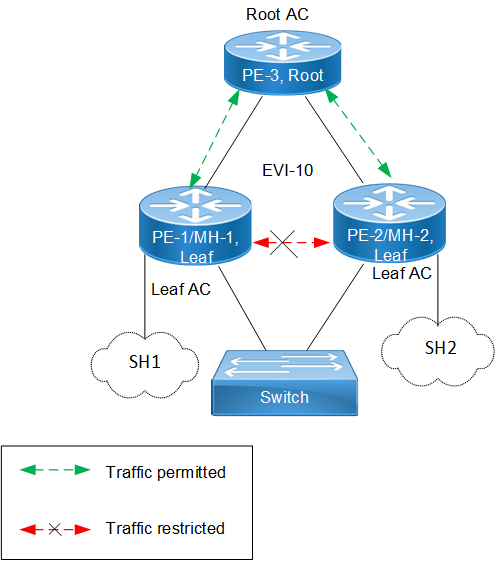
EVPN E-Tree
The classification ensures that communication follows specific rules:
• Communication between Leaf hosts is restricted, as indicated by red dotted lines with a cross mark (X) in the topology diagram. However, communication between Leaf and Root nodes, as well as between Root nodes, is permitted, marked by green dotted lines.
• Leaf nodes within PE-1 and PE-2 are isolated from each other, preventing intra-PE communication.
The scenario 1 is achieved through two main concepts:
1. Inter-PE Communication
• The inter-PE Route Target (RT) Constraint Method is applicable only to Single-Homing (SH) devices. Two RTs per broadcast domain are utilized, with Leaf PEs exporting Leaf RTs and Root nodes exporting Root RTs. Leaf nodes import only Root RTs, allowing communication with Root PEs while preventing communication with other Leaf nodes. RT constraints limit the import of specific EVPN routes (MAC-IP and IMET routes) to designated paths for inter-PE communication.
• IPI employs a proprietary method to support inter-PE connectivity for both SH and MH devices, using BGP extended community to advertise Leaf Indication in BGP routes and influence traffic flow for both Unicast and BUM traffic. This method enables implementation of ARP or ND cache suppression and MAC mobility sub-features specified in RFC-7432.
2. Intra-PE communication: Local Split Horizon controls intra-PE communication between Attachment Circuits (ACs) within Leaf PE nodes, ensuring that traffic between ACs does not egress to other Leaf ACs.
Note: This functionality depends on hardware capabilities.
Benefits
EVPN E-Tree offers benefits in networking environments by providing efficient traffic control, enhanced security, scalability, and improved performance.
Efficient Traffic Control: EVPN E-Tree allows for efficient control over traffic within network broadcast domains. By segregating nodes into Leaf and Root categories, it enables precise management of communication flows, ensuring the traffic is directed only where needed.
Enhanced Security: The isolation of Leaf hosts from each other adds a layer of security to the network. This prevents unauthorized communication between devices within the same broadcast domain, reducing the risk of data breaches and unauthorized access.
Scalability: EVPN E-Tree is scalable, making it suitable for networks of various sizes and complexities. Whether deploying in small-scale environments or large enterprise networks, EVPN E-Tree offers flexibility and scalability to meet evolving business needs.
Improved Performance: By controlling communication paths and optimizing traffic flows, EVPN E-Tree can improve network performance. This ensures that critical data packets are delivered efficiently, reducing latency and enhancing overall network performance.
Prerequisites
In setting up a VXLAN EVPN network, certain prerequisites are essential to ensure proper functionality and connectivity.
Ensure VXLAN EVPN Configuration: Confirm that VXLAN, EVPN VXLAN, and VXLAN filtering are already enabled in the network as they are required for VXLAN EVPN Multihoming.
Define Interfaces and Loopback Addresses: Configure Layer 2 interfaces, like port channel interfaces (e.g., po1), and assign specific system MAC addresses (Ethernet Segment Identifier (ESI) values) for proper identification and routing. Additionally, assign loopback IP addresses to establish essential points of connectivity. These configurations establish the efficient network routing and communication.
Configure OSPF and BGP for Dynamic Routing: Enable OSPF to facilitate dynamic routing within the network. Define OSPF router IDs to match loopback IP addresses and add network segments to OSPF areas for proper route distribution. Additionally, establish BGP sessions to advertise routes between different nodes. Set up neighbor relationships using loopback IP addresses, ensuring efficient route advertisement and convergence for optimal network performance.
Leaf Node
1. Enable VXLAN and EVPN MH
Enable features like VXLAN and EVPN Multihoming, VXLAN filtering, and quality of service (QoS) capabilities on all Leaf nodes.
!
hardware-profile filter vxlan enable
hardware-profile filter vxlan-mh enable
!
nvo vxlan enable
!
evpn vxlan multihoming enable
!
qos enable
!
2. Configure Interfaces and Loopback
Define a port channel interface (po1) as an L2 interface and assign the system MAC (0000.0000.1111) as the ESI value. Designate an interface (xe7) as a member port of po1. Assign the loopback IP address (1.1.1.1) to Leaf node, and set IP addresses (10.10.10.1 and 10.10.11.1) to interfaces (xe45 and xe49/2), respectively, for connectivity with Spine nodes.
!
interface po1
switchport
evpn multi-homed system-mac 0000.0000.1111
!
interface lo
ip address 1.1.1.1/32 secondary
!
interface xe7
channel-group 1 mode active
!
interface xe45
ip address 10.10.10.1/24
!
interface xe49/2
ip address 10.10.11.1/24
exit
!
3. Configure OSPF
In OSPF router mode, set the router ID (1.1.1.1), to match the loopback IP address. Add the loopback network (1.1.1.1/32) and networks (10.10.10.0/24 and 10.10.11.0/24) connected to Spine nodes in OSPF area 0. Enable Bidirectional Forwarding Detection (BFD) on all OSPF interfaces for faster convergence.
!
router ospf 100
ospf router-id 1.1.1.1
bfd all-interfaces
network 1.1.1.1/32 area 0.0.0.0
network 10.10.10.0/24 area 0.0.0.0
network 10.10.11.0/24 area 0.0.0.0
!
4. Configure BGP
In BGP router mode, set the router ID (1.1.1.1) to match the loopback IP address. Specify the loopback IP address of each Leaf node as neighbors with their respective remote AS numbers. Configure the loopback as the update source for each neighbor and set the advertisement interval (0) for rapid convergence. In L2VPN EVPN address family mode, activate each Leaf node (2.2.2.2, 3.3.3.3, 4.4.4.4) to establish connections within the EVPN address family.
!
router bgp 100
bgp router-id 1.1.1.1
neighbor 2.2.2.2 remote-as 100
neighbor 3.3.3.3 remote-as 100
neighbor 4.4.4.4 remote-as 100
neighbor 2.2.2.2 update-source lo
neighbor 2.2.2.2 advertisement-interval 0
neighbor 3.3.3.3 update-source lo
neighbor 3.3.3.3 advertisement-interval 0
neighbor 4.4.4.4 update-source lo
neighbor 4.4.4.4 advertisement-interval 0
!
address-family l2vpn evpn
neighbor 2.2.2.2 activate
neighbor 3.3.3.3 activate
neighbor 4.4.4.4 activate
exit-address-family
!
exit
!
5. Configure VRF
In VRF mode, create a MAC routing or forwarding instance (VRF1). Assign the Route Distinguisher (RD) value (1.1.1.1:100) and set both import and export route-target value (100:100) . Ensure that the same route-target value is configured on all Leaf nodes for MAC VRF to maintain consistency.
!
mac vrf VRF1
rd 1.1.1.1:100
route-target both 100:100
!
Spine Node
1. Configure Interfaces and Loopback
Enable QoS and assign specific IP addresses to loopback interfaces. Configure IP addresses for interfaces connected to each Leaf node.
!
qos enable
!
interface ce1/2
ip address 40.40.40.2/24
!
interface ce1/4
ip address 10.10.10.2/24
!
interface ce24/1
ip address 30.30.30.2/24
!
interface ce27/1
ip address 20.20.20.2/24
!
interface lo
ip address 5.5.5.5/32 secondary
!
2. Configure OSPF
In OSPF router mode, set the router ID (5.5.5.5), to match the loopback IP address. Add the loopback network (5.5.5.5/32) and networks (10.10.10.0/24, 20.20.20.0/24, 30.30.30.0/24, and 40.40.40.0/24) connected to Leaf nodes in OSPF area 0. Enable BFD on all OSPF interfaces for faster convergence.
!
router ospf 100
ospf router-id 5.5.5.5
bfd all-interfaces
network 5.5.5.5/32 area 0.0.0.0
network 10.10.10.0/24 area 0.0.0.0
network 20.20.20.0/24 area 0.0.0.0
network 30.30.30.0/24 area 0.0.0.0
network 40.40.40.0/24 area 0.0.0.0
!
Configure Switch
Set up an IEEE VLAN bridge, enabling VLANs and associating them with bridge 1. Configure interfaces (xe57, po1, xe46, xe47) to be part of bridge 1, setting them as hybrid ports with VLAN (1000) allowed and egress-tagged enabled. Designate interfaces connected to Leaf nodes (xe46 and xe47) as member ports of po1.
!
bridge 1 protocol ieee vlan-bridge
!
vlan database
vlan-reservation 4000-4094
vlan 1000 bridge 1 state enable
!
interface po1
switchport
bridge-group 1
switchport mode hybrid
switchport mode hybrid acceptable-frame-type all
switchport hybrid allowed vlan add 1000 egress-tagged enable
!
interface xe46
channel-group 1 mode active
!
interface xe47
channel-group 1 mode active
!
interface xe57
switchport
bridge-group 1
switchport mode hybrid
switchport mode hybrid acceptable-frame-type all
switchport hybrid allowed vlan add 1000 egress-tagged enable
!
Configuration
Configure various nodes within the topology to set up a VXLAN EVPN E-Tree network.
Topology
The sample topology includes Leaf Nodes (VTEP1, VTEP2, VTEP3, and VTEP4), Spine Nodes (SPINE1 and SPINE2), and Switches (SWITCH1 and SWITCH2).
Within this setup, VTEP1 and VTEP2 are part of Multi-homed group1, where VTEP1 is Multi-homed with po1 (MH1), and VTEP2 is Multi-homed with po1, also featuring an interface as a single home access-if port (SH1). Similarly, VTEP3 and VTEP4 are part of a Multi-homed group2, with VTEP3 Multi-homed with po2 (MH2) and VTEP4 Multi-homed with po2, along with an interface as a single home access-if port (SH2). These nodes connect to Spine nodes (SPINE1 and SPINE2), where all VTEPs are linked. Additionally, SWITCH1 and SWITCH2 are configured to be multihomed to two Leaf nodes each, with SWITCH1 connecting to VTEP1 and VTEP2 and SWITCH2 connecting to VTEP3 and VTEP4.

VXLAN EVPN E-Tree Topology
Note: Before configuring E-Tree, meet all Prerequisites for the following nodes:
• Leaf nodes: VTEP1, VTEP2, VTEP3, and VTEP4
• Spine nodes: SPINE1 and SPINE2
• Switches: SWITCH1 and SWITCH2
Enable EVPN E-Tree
The following E-Tree configurations applies to the VTEP nodes within the VXLAN network.
1. Enable EVPN E-Tree on VTEP3 and VTEP4 nodes, allowing them to participate in E-Tree functionality within the VXLAN network, controlling traffic and establishing hierarchical connections between Leaf nodes in the network architecture.
(config)#evpn etree enable
2. Set the ESI hold time (90 seconds) on all VTEP nodes to allow the tunnel to establish during VXLAN initialization before bringing up the ESI. Configure the source VTEP IP address (3.3.3.3) which serves as the global identifier for VXLAN encapsulation and decapsulation within the network, facilitating proper communication and tunnel establishment.
(config)#evpn esi hold-time 90
(config)#nvo vxlan vtep-ip-global 3.3.3.3
3. Define VXLAN identifier (10) with ingress replication and disabled inner VLAN ID (VID) for E-Tree leaf nodes (VTEP3 and VTEP4) to support hierarchical connectivity and traffic control within the VXLAN network. This configuration allows for efficient replication of traffic at the ingress point and ensures that inner VLAN IDs are disabled, optimizing the functionality of E-Tree leaf nodes within the network architecture. On the VXLAN tenant node, assign VRF (VRF1) to EVPN-BGP for carrying EVPN routes within the VXLAN network.
(config)#nvo vxlan id 10 ingress-replication inner-vid-disabled etree-leaf
(config-nvo)#vxlan host-reachability- protocol evpn-bgp VRF1
(config-nvo)#exit
4. Enable port-VLAN mapping (po2) with VLAN ID (1000) to facilitate multi-homed access on all VTEP nodes. Map VXLAN identifier (10) to the access port for VXLAN connectivity.
(config)#nvo vxlan access-if port-vlan po2 1000
(config-nvo-acc-if)#map vnid 10
(config-nvo-acc-if)#exit
(config)#commit
Validation
Use the show commands described in this section to verify the network for proper VXLAN EVPN E-Tree configuration.
Verify OSPF sessions between the VTEP nodes and the SPINEs within the VXLAN network using the show ip ospf neighbor command. This command displays OSPF neighbor details, including the state of the OSPF neighbor relationship. A State of Full/DR indicates a fully adjacent and operational state between the routers, confirming proper OSPF connectivity within the network.
VTEP1#show ip ospf neighbor
Total number of full neighbors: 2
OSPF process 100 VRF(default):
Neighbor ID Pri State Dead Time Address Interface Instance ID
5.5.5.5 1 Full/DR 00:00:32 10.10.10.2 xe45 0
6.6.6.6 1 Full/DR 00:00:30 10.10.11.2 xe49/2 0
Verify the BGP session status between VTEPs, using the show bgp l2vpn evpn summary command output. The Up/Down field indicates the duration for which the BGP session has been up or down.
VTEP1#show bgp l2vpn evpn summary
BGP router identifier 1.1.1.1, local AS number 100
BGP table version is 9
1 BGP AS-PATH entries
0 BGP community entries
Neighbor V AS MsgRcv MsgSen TblVer InQ OutQ Up/Down State/PfxRcd AD MACIP MCAST ESI PREFIX-ROUTE
2.2.2.2 4 100 34 28 7 0 0 00:07:37 9 3 4 1 1 0
3.3.3.3 4 100 30 33 8 0 0 00:07:34 6 3 2 1 0 0
4.4.4.4 4 100 31 28 7 0 0 00:07:37 8 3 4 1 0 0
Total number of neighbors 3
Total number of Established sessions 3
To validate the BGP L2VPN output on VTEPs and check MAC-IP routes and ESI information, use the show bgp l2vpn evpn command output. This command verifies routes with status code i (internal) and EVPN route types 2 and 4, displaying detailed information for each VTEP nodes.
VTEP1#show bgp l2vpn evpn
BGP table version is 9, local router ID is 1.1.1.1
Status codes: s suppressed, d damped, h history, a add-path, b back-up, * valid, > best, i - internal,
l - labeled, S Stale
Origin codes: i - IGP, e - EGP, ? - incomplete
[EVPN route type]:[ESI]:[VNID]:[relevent route informantion]
1 - Ethernet Auto-discovery Route
2 - MAC/IP Route
3 - Inclusive Multicast Route
4 - Ethernet Segment Route
5 - Prefix Route
Network Next Hop Metric LocPrf Weight Path Peer Encap
RD[1.1.1.1:100] VRF[VRF1]:
*> [1]:[00:00:00:00:00:11:11:00:00:00]:[10]:[10]
1.1.1.1 0 100 32768 i ---------- VXLAN
* i 2.2.2.2 0 100 0 i 2.2.2.2 VXLAN
*> [1]:[00:00:00:00:00:11:11:00:00:00]:[4294967295]:[0]
1.1.1.1 0 100 32768 i ---------- VXLAN
* i 2.2.2.2 0 100 0 i 2.2.2.2 VXLAN
* i 2.2.2.2 0 100 0 i 2.2.2.2 VXLAN
* i[1]:[00:00:00:00:00:22:22:00:00:00]:[10]:[10]
3.3.3.3 0 100 0 i 3.3.3.3 VXLAN
* i 4.4.4.4 0 100 0 i 4.4.4.4 VXLAN
* i[1]:[00:00:00:00:00:22:22:00:00:00]:[4294967295]:[0]
3.3.3.3 0 100 0 i 3.3.3.3 VXLAN
* i 3.3.3.3 0 100 0 i 3.3.3.3 VXLAN
* i 4.4.4.4 0 100 0 i 4.4.4.4 VXLAN
* i 4.4.4.4 0 100 0 i 4.4.4.4 VXLAN
*> [2]:[00:00:00:00:00:11:11:00:00:00]:[10]:[48,0000:1000:1000]:[32,100.100.100.1]:[10]
1.1.1.1 0 100 32768 i ---------- VXLAN
* i 2.2.2.2 0 100 0 i 2.2.2.2 VXLAN
*> [2]:[00:00:00:00:00:11:11:00:00:00]:[10]:[48,0000:1000:1001]:[128,1000::1][10]
1.1.1.1 0 100 32768 i ---------- VXLAN
* i 2.2.2.2 0 100 0 i 2.2.2.2 VXLAN
* i[2]:[0]:[10]:[48,0000:2000:2000]:[32,200.200.200.1]:[10]
2.2.2.2 0 100 0 i 2.2.2.2 VXLAN
* i[2]:[0]:[10]:[48,0000:2000:2001]:[128,2000::1][10]
2.2.2.2 0 100 0 i 2.2.2.2 VXLAN
* i[2]:[00:00:00:00:00:22:22:00:00:00]:[10]:[48,0000:3000:3000]:[32,103.103.103.1]:[10]
3.3.3.3 0 100 0 i 3.3.3.3 VXLAN
* i 4.4.4.4 0 100 0 i 4.4.4.4 VXLAN
* i[2]:[00:00:00:00:00:22:22:00:00:00]:[10]:[48,0000:3000:3001]:[128,1003::1][10]
3.3.3.3 0 100 0 i 3.3.3.3 VXLAN
* i 4.4.4.4 0 100 0 i 4.4.4.4 VXLAN
* i[2]:[0]:[10]:[48,0000:4000:4000]:[32,104.104.104.1]:[10]
4.4.4.4 0 100 0 i 4.4.4.4 VXLAN
* i[2]:[0]:[10]:[48,0000:4000:4001]:[128,1004::1][10]
4.4.4.4 0 100 0 i 4.4.4.4 VXLAN
*> [3]:[10]:[32,1.1.1.1]
1.1.1.1 0 100 32768 i ---------- VXLAN
* i[3]:[10]:[32,2.2.2.2]
2.2.2.2 0 100 0 i 2.2.2.2 VXLAN
* i[3]:[10]:[32,3.3.3.3]
3.3.3.3 0 100 0 i 3.3.3.3 VXLAN
* i[3]:[10]:[32,4.4.4.4]
4.4.4.4 0 100 0 i 4.4.4.4 VXLAN
RD[1.1.1.1:64512] VRF[evpn-gvrf-1]:
*> [1]:[00:00:00:00:00:11:11:00:00:00]:[4294967295]:[0]
1.1.1.1 0 100 32768 i ---------- VXLAN
*> [4]:[00:00:00:00:00:11:11:00:00:00]:[32,1.1.1.1]
1.1.1.1 0 100 32768 i ---------- VXLAN
* i[4]:[00:00:00:00:00:11:11:00:00:00]:[32,2.2.2.2]
2.2.2.2 0 100 0 i 2.2.2.2 VXLAN
RD[2.2.2.2:100]
*>i[1]:[00:00:00:00:00:11:11:00:00:00]:[10]:[10]
2.2.2.2 0 100 0 i 2.2.2.2 VXLAN
*>i[1]:[00:00:00:00:00:11:11:00:00:00]:[4294967295]:[0]
2.2.2.2 0 100 0 i 2.2.2.2 VXLAN
*>i[2]:[00:00:00:00:00:11:11:00:00:00]:[10]:[48,0000:1000:1000]:[32,100.100.100.1]:[10]
2.2.2.2 0 100 0 i 2.2.2.2 VXLAN
*>i[2]:[00:00:00:00:00:11:11:00:00:00]:[10]:[48,0000:1000:1001]:[128,1000::1][10]
2.2.2.2 0 100 0 i 2.2.2.2 VXLAN
*>i[2]:[0]:[10]:[48,0000:2000:2000]:[32,200.200.200.1]:[10]
2.2.2.2 0 100 0 i 2.2.2.2 VXLAN
*>i[2]:[0]:[10]:[48,0000:2000:2001]:[128,2000::1][10]
2.2.2.2 0 100 0 i 2.2.2.2 VXLAN
*>i[3]:[10]:[32,2.2.2.2]
2.2.2.2 0 100 0 i 2.2.2.2 VXLAN
RD[2.2.2.2:64512]
*>i[1]:[00:00:00:00:00:11:11:00:00:00]:[4294967295]:[0]
2.2.2.2 0 100 0 i 2.2.2.2 VXLAN
*>i[4]:[00:00:00:00:00:11:11:00:00:00]:[32,2.2.2.2]
2.2.2.2 0 100 0 i 2.2.2.2 VXLAN
RD[3.3.3.3:100]
*>i[1]:[00:00:00:00:00:22:22:00:00:00]:[10]:[10]
3.3.3.3 0 100 0 i 3.3.3.3 VXLAN
*>i[1]:[00:00:00:00:00:22:22:00:00:00]:[4294967295]:[0]
3.3.3.3 0 100 0 i 3.3.3.3 VXLAN
*>i[2]:[00:00:00:00:00:22:22:00:00:00]:[10]:[48,0000:3000:3000]:[32,103.103.103.1]:[10]
3.3.3.3 0 100 0 i 3.3.3.3 VXLAN
*>i[2]:[00:00:00:00:00:22:22:00:00:00]:[10]:[48,0000:3000:3001]:[128,1003::1][10]
3.3.3.3 0 100 0 i 3.3.3.3 VXLAN
*>i[3]:[10]:[32,3.3.3.3]
3.3.3.3 0 100 0 i 3.3.3.3 VXLAN
RD[3.3.3.3:64512]
*>i[1]:[00:00:00:00:00:22:22:00:00:00]:[4294967295]:[0]
3.3.3.3 0 100 0 i 3.3.3.3 VXLAN
RD[4.4.4.4:100]
*>i[1]:[00:00:00:00:00:22:22:00:00:00]:[10]:[10]
4.4.4.4 0 100 0 i 4.4.4.4 VXLAN
*>i[1]:[00:00:00:00:00:22:22:00:00:00]:[4294967295]:[0]
4.4.4.4 0 100 0 i 4.4.4.4 VXLAN
*>i[2]:[00:00:00:00:00:22:22:00:00:00]:[10]:[48,0000:3000:3000]:[32,103.103.103.1]:[10]
4.4.4.4 0 100 0 i 4.4.4.4 VXLAN
*>i[2]:[00:00:00:00:00:22:22:00:00:00]:[10]:[48,0000:3000:3001]:[128,1003::1][10]
4.4.4.4 0 100 0 i 4.4.4.4 VXLAN
*>i[2]:[0]:[10]:[48,0000:4000:4000]:[32,104.104.104.1]:[10]
4.4.4.4 0 100 0 i 4.4.4.4 VXLAN
*>i[2]:[0]:[10]:[48,0000:4000:4001]:[128,1004::1][10]
4.4.4.4 0 100 0 i 4.4.4.4 VXLAN
*>i[3]:[10]:[32,4.4.4.4]
4.4.4.4 0 100 0 i 4.4.4.4 VXLAN
RD[4.4.4.4:64512]
*>i[1]:[00:00:00:00:00:22:22:00:00:00]:[4294967295]:[0]
4.4.4.4 0 100 0 i 4.4.4.4 VXLAN
Total number of prefixes 42
Validate the LAG interfaces (po1 and po2) are up for MH1 and MH2 by reviewing the show etherchannel summary output. Check the Link and sync fields, where link displays the port channel interface and ID number, and sync indicates whether MAC address synchronization is enabled to forward Layer 3 packets arriving on these interfaces.
VTEP1#show etherchannel summary
Aggregator po1 100001
Aggregator Type: Layer2
Admin Key: 0001 - Oper Key 0001
Link: xe7 (5005) sync: 1
Validate the status of NVO VXLAN on VTEPs by examining the output of the show nvo vxlan command. The DF-Status field displays the forwarding status of VXLAN tunnels as a Designated Forwarder (DF) or Non-Designated Forwarder (Non-DF).
VTEP1#show nvo vxlan
VXLAN Information
=================
Codes: NW - Network Port
AC - Access Port
(u) - Untagged
VNID VNI-Name VNI-Type Type Interface ESI VLAN DF-Status Src-Addr Dst-Addr
____________________________________________________________________________________________________________________________
10 ---- L2 NW ---- ---- ---- ---- 1.1.1.1 4.4.4.4
10 ---- L2 NW ---- ---- ---- ---- 1.1.1.1 3.3.3.3
10 ---- L2 NW ---- ---- ---- ---- 1.1.1.1 2.2.2.2
10 ---- -- AC po1 00:00:00:00:00:11:11:00:00:00 1000 DF ---- ----
Total number of entries are 4
VTEP2#show nvo vxlan
VXLAN Information
=================
Codes: NW - Network Port
AC - Access Port
(u) - Untagged
VNID VNI-Name VNI-Type Type Interface ESI VLAN DF-Status Src-Addr Dst-Addr
___________________________________________________________________________________________________________________________
10 ---- L2 NW ---- ---- ---- ---- 2.2.2.2 4.4.4.4
10 ---- L2 NW ---- ---- ---- ---- 2.2.2.2 1.1.1.1
10 ---- L2 NW ---- ---- ---- ---- 2.2.2.2 3.3.3.3
10 ---- -- AC xe37 --- Single Homed Port --- 1000 ---- ---- ----
10 ---- -- AC po1 00:00:00:00:00:11:11:00:00:00 1000 NON-DF ---- ----
Total number of entries are 5
VTEP3#show nvo vxlan
VXLAN Information
=================
Codes: NW - Network Port
AC - Access Port
(u) - Untagged
VNID VNI-Name VNI-Type Type Interface ESI VLAN DF-Status Src-Addr Dst-Addr
___________________________________________________________________________________________________________________________
10 ---- L2 NW ---- ---- ---- ---- 3.3.3.3 2.2.2.2
10 ---- L2 NW ---- ---- ---- ---- 3.3.3.3 1.1.1.1
10 ---- L2 NW ---- ---- ---- ---- 3.3.3.3 4.4.4.4
10 ---- -- AC po2 00:00:00:00:00:22:22:00:00:00 1000 DF ---- ----
Total number of entries are 4
VTEP4#show nvo vxlan
VXLAN Information
=================
Codes: NW - Network Port
AC - Access Port
(u) - Untagged
VNID VNI-Name VNI-Type Type Interface ESI VLAN DF-Status Src-Addr Dst-Addr
___________________________________________________________________________________________________________________________
10 ---- L2 NW ---- ---- ---- ---- 4.4.4.4 2.2.2.2
10 ---- L2 NW ---- ---- ---- ---- 4.4.4.4 3.3.3.3
10 ---- L2 NW ---- ---- ---- ---- 4.4.4.4 1.1.1.1
10 ---- -- AC xe34 --- Single Homed Port --- 1000 ---- ---- ----
10 ---- -- AC po2 00:00:00:00:00:22:22:00:00:00 1000 NON-DF ---- ----
Total number of entries are 5
Validate the NVO VXLAN tunnel status on VTEPs by reviewing the output of the show nvo vxlan tunnel command. The Status field indicates the current status of each tunnel. In this case, all three tunnels between VTEPs and their respective destinations are marked as Installed, confirming that these tunnels are successfully established and operating.
VTEP1#show nvo vxlan tunnel
VXLAN Network tunnel Entries
Source Destination Status Up/Down Update
========================================================================
1.1.1.1 4.4.4.4 Installed 00:02:26 00:01:58
1.1.1.1 3.3.3.3 Installed 00:02:26 00:01:55
1.1.1.1 2.2.2.2 Installed 00:02:25 00:01:55
Total number of entries are 3
Validate the VXLAN access interface status on VTEPs by examining the output of the show nvo vxlan access-if brief command. The up admin and link status confirms that the access port associated with VXLAN is active and functioning properly on the VTEP nodes.
VTEP1#show nvo vxlan access-if brief
Inner Admin Link
Interface Vlan vlan Ifindex Vnid status status
---------------------------------------------------------------
po1 1000 --- 0x7a120 10 up up
Total number of entries are 1
Static MAC-IP Advertisement
Configure static MAC-IP advertisement through SH and MH VTEPs from Root and Leaf nodes. Advertise static MAC addresses for IPv4 and IPv6 from MH1, MH2, SH1, and SH2 VTEPs. Ensure that VTEP1 and VTEP2 in MH1 have the same MAC addresses configured under the port-channel access port. Symmetrical configurations between MH VTEPs should be maintained.
Configure MH1 and MH2 VTEPs
Configure static MAC addresses for IPv4 (100.100.100.1) and IPv6 (1000::1) under the VXLAN MH access-port (po1) with VLAN ID (1000). Ensure that identical MAC addresses are set up within the MH1-VTEPs for advertisement. Apply similar configurations to MH2-VTEPs for static MAC-IP advertisement.
!
nvo vxlan access-if port-vlan po1 1000
map vnid 10
mac 0000.1000.1000 ip 100.100.100.1
mac 0000.1000.1001 ipv6 1000::1
!
Configure SH1 and SH2 VTEPs
Configure static MAC addresses for IPv4 (200.200.200.1) and IPv6 (2000::1) under the VXLAN SH access-port (xe37) with VLAN ID (1000) on SH1 (VTEP2). This setup ensures that SH1 advertises these static MAC addresses over the specified VXLAN access-port. Repeat similar configurations for SH2 (VTEP4) using different static MAC addresses for both IPv4 and IPv6.
!
nvo vxlan access-if port-vlan xe37 1000
map vnid 10
mac 0000.2000.2000 ip 200.200.200.1
mac 0000.2000.2001 ipv6 2000::1
!
Validation
Verify the MAC table entries on MH VTEPs (MH1 and MH2) and the SH VTEPs (VTEP2 and VTEP4). The MAC addresses are advertised using the ESI values from VTEP1 and VTEP2 for MH1, and from VTEP3 and VTEP4 for MH2. Additionally, verify the VTEP IP addresses associated with SH VTEP2 and VTEP4 for MAC advertisement.
In the output of the show nvo vxlan mac-table command on all VTEP nodes, the MAC entries advertised from Leaf VTEPs will have the LeafFlag field status set.
Note:
• MAC IPv4 or IPv6 configured under SH Leaf VTEP access port will be advertised to the Root VTEP and other Leaf VTEPs.
• MAC IPv4 or IPv6 configured under an MH Leaf VTEP access port must be symmetric and will be advertised to both the Root VTEP and other leaf VTEPs.
• MAC IPv4 or IPv6 configured under either SH or MH Root VTEP will be advertised to both the Root VTEP and the Leaf VTEPs.
• The Leaf-to-Leaf communication will display MAC status and tunnel status per VNI as Leaf type. The MAC will be in the discard state in the BCM shell.
VTEP1#show nvo vxlan mac-table
============================================================================================================================
VXLAN MAC Entries
============================================================================================================================
VNID Interface VlanId In-VlanId Mac-Addr VTEP-Ip/ESI Type Status MAC move AccessPortDesc LeafFlag
____________________________________________________________________________________________________________________________
10 po1 1000 ---- 0000.1000.1000 00:00:00:00:00:11:11:00:00:00 Static Local ------- 0 ------- ----
10 po1 1000 ---- 0000.1000.1001 00:00:00:00:00:11:11:00:00:00 Static Local ------- 0 ------- ----
10 ---- ---- ---- 0000.2000.2000 2.2.2.2 Static Remote ------- 0 ------- ----
10 ---- ---- ---- 0000.2000.2001 2.2.2.2 Static Remote ------- 0 ------- ----
10 ---- ---- ---- 0000.3000.3000 00:00:00:00:00:22:22:00:00:00 Static Remote ------- 0 ------- set
10 ---- ---- ---- 0000.3000.3001 00:00:00:00:00:22:22:00:00:00 Static Remote ------- 0 ------- set
10 ---- ---- ---- 0000.4000.4000 4.4.4.4 Static Remote ------- 0 ------- set
10 ---- ---- ---- 0000.4000.4001 4.4.4.4 Static Remote ------- 0 ------- set
Total number of entries are : 8
VTEP3#show nvo vxlan mac-table
===========================================================================================================================
VXLAN MAC Entries
============================================================================================================================
VNID Interface VlanId In-VlanId Mac-Addr VTEP-Ip/ESI Type Status MAC move AccessPortDesc LeafFlag
___________________________________________________________________________________________________________________________
10 ---- ---- ---- 0000.1000.1000 00:00:00:00:00:11:11:00:00:00 Static Remote ------- 0 ------- ----
10 ---- ---- ---- 0000.1000.1001 00:00:00:00:00:11:11:00:00:00 Static Remote ------- 0 ------- ----
10 ---- ---- ---- 0000.2000.2000 2.2.2.2 Static Remote ------- 0 ------- ----
10 ---- ---- ---- 0000.2000.2001 2.2.2.2 Static Remote ------- 0 ------- ----
10 po2 1000 ---- 0000.3000.3000 00:00:00:00:00:22:22:00:00:00 Static Local ------- 0 ------- set
10 po2 1000 ---- 0000.3000.3001 00:00:00:00:00:22:22:00:00:00 Static Local ------- 0 ------- set
10 ---- ---- ---- 0000.4000.4000 4.4.4.4 Static Remote ------- 0 ------- set
10 ---- ---- ---- 0000.4000.4001 4.4.4.4 Static Remote ------- 0 ------- set
Total number of entries are : 8
Use the show nvo vxlan arp-cache command to verify the Address Resolution Protocol (ARP) cache information on all VTEP nodes. This command displays entries that map IPv4 addresses to MAC addresses within the specified VXLAN VNID network.
VTEP1#show nvo vxlan arp-cache
VXLAN ARP-CACHE Information
===========================
VNID Ip-Addr Mac-Addr Type Age-Out Retries-Left
____________________________________________________________________________
10 100.100.100.1 0000.1000.1000 Static Local ----
10 103.103.103.1 0000.3000.3000 Static Remote ----
10 104.104.104.1 0000.4000.4000 Static Remote ----
10 200.200.200.1 0000.2000.2000 Static Remote ----
Total number of entries are 4
VTEP3#show nvo vxlan arp-cache
VXLAN ARP-CACHE Information
===========================
VNID Ip-Addr Mac-Addr Type Age-Out Retries-Left
____________________________________________________________________________
10 100.100.100.1 0000.1000.1000 Static Remote ----
10 103.103.103.1 0000.3000.3000 Static Local ----
10 104.104.104.1 0000.4000.4000 Static Remote ----
10 200.200.200.1 0000.2000.2000 Static Remote ----
Total number of entries are 4
Use the show nvo vxlan nd-cache command to verify the Neighbor Discovery (ND) cache information on all VTEP nodes. This command displays entries that map IPv6 addresses to MAC addresses within the specified VXLAN VNID network.
VTEP1#show nvo vxlan nd-cache
VXLAN ND-CACHE Information
===========================
VNID Ip-Addr Mac-Addr Type Age-Out Retries-Left
______________________________________________________________________________
10 1000::1 0000.1000.1001 Static Local ----
10 1003::1 0000.3000.3001 Static Remote ----
10 1004::1 0000.4000.4001 Static Remote ----
10 2000::1 0000.2000.2001 Static Remote ----
Total number of entries are 4
VTEP3#show nvo vxlan nd-cache
VXLAN ND-CACHE Information
===========================
VNID Ip-Addr Mac-Addr Type Age-Out Retries-Left
____________________________________________________________________________________________________
10 1000::1 0000.1000.1001 Static Remote ----
10 1003::1 0000.3000.3001 Static Local ----
10 1004::1 0000.4000.4001 Static Remote ----
10 2000::1 0000.2000.2001 Static Remote ----
Total number of entries are 4
Network Topology Snippet Configurations
Here are the snippet configurations for all nodes in the given network topology.
VTEP1
!
hardware-profile filter vxlan enable
hardware-profile filter vxlan-mh enable
!
nvo vxlan enable
!
evpn esi hold-time 90
!
evpn vxlan multihoming enable
!
mac vrf VRF1
rd 1.1.1.1:100
route-target both 100:100
!
nvo vxlan vtep-ip-global 1.1.1.1
!
nvo vxlan id 10 ingress-replication inner-vid-disabled
vxlan host-reachability-protocol evpn-bgp VRF1
!
qos enable
!
hardware-profile filter vxlan enable
hardware-profile filter vxlan-mh enable
!
interface po1
switchport
evpn multi-homed system-mac 0000.0000.1111
!
interface lo
ip address 1.1.1.1/32 secondary
!
interface xe7
channel-group 1 mode active
!
interface xe45
ip address 10.10.10.1/24
!
interface xe49/2
ip address 10.10.11.1/24
!
exit
!
router ospf 100
ospf router-id 1.1.1.1
bfd all-interfaces
network 1.1.1.1/32 area 0.0.0.0
network 10.10.10.0/24 area 0.0.0.0
network 10.10.11.0/24 area 0.0.0.0
!
router bgp 100
bgp router-id 1.1.1.1
neighbor 2.2.2.2 remote-as 100
neighbor 3.3.3.3 remote-as 100
neighbor 4.4.4.4 remote-as 100
neighbor 2.2.2.2 update-source lo
neighbor 2.2.2.2 advertisement-interval 0
neighbor 3.3.3.3 update-source lo
neighbor 3.3.3.3 advertisement-interval 0
neighbor 4.4.4.4 update-source lo
neighbor 4.4.4.4 advertisement-interval 0
!
address-family l2vpn evpn
neighbor 2.2.2.2 activate
neighbor 3.3.3.3 activate
neighbor 4.4.4.4 activate
exit-address-family
!
exit
!
nvo vxlan access-if port-vlan po1 1000
map vnid 10
mac 0000.1000.1000 ip 100.100.100.1
mac 0000.1000.1001 ipv6 1000::1
!
VTEP2
!
hardware-profile filter vxlan enable
hardware-profile filter vxlan-mh enable
!
nvo vxlan enable
!
evpn esi hold-time 90
!
evpn vxlan multihoming enable
!
mac vrf VRF1
rd 2.2.2.2:100
route-target both 100:100
!
nvo vxlan vtep-ip-global 2.2.2.2
!
nvo vxlan id 10 ingress-replication inner-vid-disabled
vxlan host-reachability-protocol evpn-bgp VRF1
!
qos enable
!
hardware-profile filter vxlan enable
hardware-profile filter vxlan-mh enable
!
interface po1
switchport
evpn multi-homed system-mac 0000.0000.1111
!
interface lo
ip address 2.2.2.2/32 secondary
!
interface xe38
channel-group 1 mode active
!
interface xe49/1
ip address 20.20.20.1/24
!
interface xe50/1
ip address 20.20.21.1/24
!
exit
!
router ospf 100
ospf router-id 2.2.2.2
bfd all-interfaces
network 2.2.2.2/32 area 0.0.0.0
network 20.20.20.0/24 area 0.0.0.0
network 20.20.21.0/24 area 0.0.0.0
!
router bgp 100
bgp router-id 2.2.2.2
neighbor 1.1.1.1 remote-as 100
neighbor 3.3.3.3 remote-as 100
neighbor 4.4.4.4 remote-as 100
neighbor 1.1.1.1 update-source lo
neighbor 1.1.1.1 advertisement-interval 0
neighbor 3.3.3.3 update-source lo
neighbor 3.3.3.3 advertisement-interval 0
neighbor 4.4.4.4 update-source lo
neighbor 4.4.4.4 advertisement-interval 0
!
address-family l2vpn evpn
neighbor 1.1.1.1 activate
neighbor 3.3.3.3 activate
neighbor 4.4.4.4 activate
exit-address-family
!
exit
!
nvo vxlan access-if port-vlan xe37 1000
map vnid 10
mac 0000.2000.2000 ip 200.200.200.1
mac 0000.2000.2001 ipv6 2000::1
!
nvo vxlan access-if port-vlan po1 1000
map vnid 10
mac 0000.1000.1000 ip 100.100.100.1
mac 0000.1000.1001 ipv6 1000::1
!
VTEP3
!
hardware-profile filter vxlan enable
hardware-profile filter vxlan-mh enable
!
nvo vxlan enable
!
evpn esi hold-time 90
!
evpn vxlan multihoming enable
!
evpn etree enable
!
mac vrf VRF1
rd 3.3.3.3:100
route-target both 100:100
!
nvo vxlan vtep-ip-global 3.3.3.3
!
nvo vxlan id 10 ingress-replication inner-vid-disabled etree-leaf
vxlan host-reachability-protocol evpn-bgp VRF1
!
qos enable
!
interface po2
switchport
evpn multi-homed system-mac 0000.0000.2222
!
interface lo
ip address 3.3.3.3/32 secondary
!
interface xe53/1
ip address 30.30.30.1/24
!
interface xe54/1
ip address 30.30.31.1/24
!
interface xe55/1
channel-group 2 mode active
!
exit
!
router ospf 100
ospf router-id 3.3.3.3
bfd all-interfaces
network 3.3.3.3/32 area 0.0.0.0
network 30.30.30.0/24 area 0.0.0.0
network 30.30.31.0/24 area 0.0.0.0
!
router bgp 100
bgp router-id 3.3.3.3
neighbor 1.1.1.1 remote-as 100
neighbor 2.2.2.2 remote-as 100
neighbor 4.4.4.4 remote-as 100
neighbor 1.1.1.1 update-source lo
neighbor 1.1.1.1 advertisement-interval 0
neighbor 2.2.2.2 update-source lo
neighbor 2.2.2.2 advertisement-interval 0
neighbor 4.4.4.4 update-source lo
neighbor 4.4.4.4 advertisement-interval 0
!
address-family l2vpn evpn
neighbor 1.1.1.1 activate
neighbor 2.2.2.2 activate
neighbor 4.4.4.4 activate
exit-address-family
!
exit
!
!
nvo vxlan access-if port-vlan po2 1000
map vnid 10
mac 0000.3000.3000 ip 103.103.103.1
mac 0000.3000.3001 ipv6 1003::1
!
VTEP4
!
hardware-profile filter vxlan enable
hardware-profile filter vxlan-mh enable
!
nvo vxlan enable
!
evpn esi hold-time 90
!
evpn vxlan multihoming enable
!
evpn etree enable
!
mac vrf VRF1
rd 4.4.4.4:100
route-target both 100:100
!
nvo vxlan vtep-ip-global 4.4.4.4
!
nvo vxlan id 10 ingress-replication inner-vid-disabled etree-leaf
vxlan host-reachability-protocol evpn-bgp VRF1
!
qos enable
!
interface po2
switchport
evpn multi-homed system-mac 0000.0000.2222
!
interface lo
ip address 4.4.4.4/32 secondary
!
interface xe11/1
ip address 40.40.41.1/24
!
interface xe31/1
channel-group 2 mode active
!
interface xe33
ip address 40.40.40.1/24
!
interface xe34
switchport
!
exit
!
router ospf 100
ospf router-id 4.4.4.4
bfd all-interfaces
network 4.4.4.4/32 area 0.0.0.0
network 40.40.40.0/24 area 0.0.0.0
network 40.40.41.0/24 area 0.0.0.0
!
router bgp 100
bgp router-id 4.4.4.4
neighbor 1.1.1.1 remote-as 100
neighbor 2.2.2.2 remote-as 100
neighbor 3.3.3.3 remote-as 100
neighbor 1.1.1.1 update-source lo
neighbor 1.1.1.1 advertisement-interval 0
neighbor 2.2.2.2 update-source lo
neighbor 2.2.2.2 advertisement-interval 0
neighbor 3.3.3.3 update-source lo
neighbor 3.3.3.3 advertisement-interval 0
!
address-family l2vpn evpn
neighbor 1.1.1.1 activate
neighbor 2.2.2.2 activate
neighbor 3.3.3.3 activate
exit-address-family
!
exit
!
nvo vxlan access-if port-vlan xe34 1000
map vnid 10
mac 0000.4000.4000 ip 104.104.104.1
mac 0000.4000.4001 ipv6 1004::1
!
nvo vxlan access-if port-vlan po2 1000
map vnid 10
mac 0000.3000.3000 ip 103.103.103.1
mac 0000.3000.3001 ipv6 1003::1
!
SPINE1
!
qos enable
!
interface ce1/2
ip address 40.40.40.2/24
!
interface ce1/4
ip address 10.10.10.2/24
!
interface ce24/1
ip address 30.30.30.2/24
!
interface ce27/1
ip address 20.20.20.2/24
!
interface lo
ip address 5.5.5.5/32 secondary
!
exit
!
router ospf 100
ospf router-id 5.5.5.5
bfd all-interfaces
network 5.5.5.5/32 area 0.0.0.0
network 10.10.10.0/24 area 0.0.0.0
network 20.20.20.0/24 area 0.0.0.0
network 30.30.30.0/24 area 0.0.0.0
network 40.40.40.0/24 area 0.0.0.0
!
SPINE2
!
qos enable
!
interface ce5/1
ip address 20.20.21.2/24
!
interface ce10/1
ip address 30.30.31.2/24
!
interface ce11/1
ip address 40.40.41.2/24
!
interface ce14/2
ip address 10.10.11.2/24
!
interface lo
ip address 6.6.6.6/32 secondary
!
exit
!
router ospf 100
ospf router-id 6.6.6.6
bfd all-interfaces
network 6.6.6.6/32 area 0.0.0.0
network 10.10.11.0/24 area 0.0.0.0
network 20.20.21.0/24 area 0.0.0.0
network 30.30.31.0/24 area 0.0.0.0
network 40.40.41.0/24 area 0.0.0.0
!
SWITCH1
!
bridge 1 protocol ieee vlan-bridge
!
vlan database
vlan-reservation 4000-4094
vlan 1000 bridge 1 state enable
!
interface po1
switchport
bridge-group 1
switchport mode hybrid
switchport mode hybrid acceptable-frame-type all
switchport hybrid allowed vlan add 1000 egress-tagged enable
!
interface xe46
channel-group 1 mode active
!
interface xe47
channel-group 1 mode active
!
interface xe57
switchport
bridge-group 1
switchport mode hybrid
switchport mode hybrid acceptable-frame-type all
switchport hybrid allowed vlan add 1000 egress-tagged enable
!
exit
!
SWITCH2
!
bridge 1 protocol ieee vlan-bridge
!
vlan database
vlan-reservation 4000-4094
vlan 1000 bridge 1 state enable
!
interface po2
switchport
bridge-group 1
switchport mode hybrid
switchport mode hybrid acceptable-frame-type all
switchport hybrid allowed vlan add 1000 egress-tagged enable
!
interface xe33
switchport
bridge-group 1
switchport mode hybrid
switchport mode hybrid acceptable-frame-type all
switchport hybrid allowed vlan add 1000 egress-tagged enable
!
interface xe49/1
channel-group 2 mode active
!
interface xe51/1
channel-group 2 mode active
!
exit
!
Implementation Examples
Here is an example scenario and a solution for implementing EVPN E-Tree.
Scenario 1: Specific traffic isolation and control measures are essential in a network of EVPN L2VPN services or instances. Within a broadcast domain, services communicating with each other may result in flooding BUM traffic to all services within the domain. Moreover, hosts are learned and advertised between different sites/services.
Use Case 1: Implementing an EVPN E-Tree solution defines the network topology with distinct Root and Leaf classifications, BUM traffic flooding can be minimized, and traffic isolation can be achieved. This ensures efficient communication between services while preventing unnecessary traffic propagation and maintaining network integrity.
Scenario 2: An Internet Service Provider (ISP) provides services to multiple subscribers and aims to facilitate communication with them. However, the ISP needs to ensure that subscribers exclusively communicate with the ISP and not among themselves.
Use Case 2: Implementing EVPN E-Tree is essential to fulfill this requirement. By categorizing ISP services as Root and subscribers as Leaf, traffic isolation can be enforced. This configuration enables the ISP to communicate with subscribers while preventing inter-subscriber communication. As a result, network security is enhanced, and the ISP maintains control over communication within its network.
E-Tree CLI Commands
The EVPN E-Tree introduces the following configuration commands in OcNOS.
evpn etree
Use this command to enable E-Tree functionality within the EVPN configuration.
Command Syntax
evpn etree enable
Parameters
None
Default
Disabled
Command Mode
Configure mode
Applicability
Introduced in OcNOS version 6.5.1.
Example
The following example illustrates how to activate E-Tree functionality for EVPN:
OcNOS#configure terminal
OcNOS(config)#evpn etree enable
Revised CLI Commands
The following is the revised command for configuring VXLAN EVPN E-Tree
nvo vxlan id
• The existing syntax now includes the newly added parameter for E-Tree, namely etree-leaf.
• The command nvo vxlan id <VNID> ingress-replication inner-vid-disabled etree-leaf allows users to tailor VXLAN behavior on a network device, specifying VXLAN parameters and indicating its participation as a leaf node in an E-Tree deployment. For more details, refer to the nvo vxlan id command in the VXLAN Commands chapter in the OcNOS VXLAN Guide.
Troubleshooting
1. When traffic, whether unicast (UC) or broadcast, is passed to the Intra Leaf site:
• Check the sub-interface or physical interface counters to monitor traffic throughput and potential issues.
• Verify the Leaf status of the corresponding VNI to ensure proper functionality.
• Use packet sniffing tools to analyze packets in the egress direction for any anomalies or errors.
• MAC entries learned via leaf access port should include the set keyword in the MAC table output.
2. If UC traffic is routed within inter-PE leaf sites:
• Check the Leaf status of the VNI at both participating PE devices to confirm operational status.
• Check if the advertised MAC is in discard or non-discard status using the show mac table command and l2 show in the BCM shell.
3. Verify if BUM traffic is transmitted between Leaf sites inter-PE:
• Ensure that a BUM tunnels are not established between inter-PE devices.
• Validate this by examining the Multicast ingress group, using the show evpn mpls tunnel command. For EVPN MPLS, confirm that BUM tunnels are not created.
4. Investigate UC traffic drops from the Root to MH Leaf PE:
• Check if MAC addresses are not installed in discard status within the MH peer's access port. This status could indicate issues with MAC learning or forwarding.
5. Evaluate traffic between Root and Leaf:
• Confirm the establishment of both UC and BUM tunnels.
• Ensure that unicast MAC addresses are not marked with a discard status in the MAC table.
6. Validate the exchange of routes between two BGP L2VPN peers:
• Monitor BGP (Border Gateway Protocol) sessions to verify successful route exchange and propagation between the peers.
7. Convergence: Assess convergence by checking BFD configuration between BGP sessions.
Glossary
The following provides definitions for key terms or abbreviations and their meanings used throughout this document:
Key Terms/Acronym | Description |
Ethernet VPN Ethernet-Tree (EVPN E-Tree) | A networking solution designed to manage communication within broadcast domains, incorporating redundancy through multi-homing in a network. It optimizes traffic routing and control, categorizing network nodes based on predefined definitions of EVPN Instances as Leaf or Root, allowing or restricting communication between them. |
Virtual Extensible LAN (VXLAN) | A technology that provides encapsulation techniques to create virtualized Layer 2 networks over Layer 3 infrastructure, facilitating scalable and flexible network designs. |
Ethernet Virtual Private Network (EVPN) | A Layer 2 VPN technology that extends Ethernet services across data centers and wide-area networks using BGP. |
Multi-homing (MH) | The ability of a device to connect to multiple network segments simultaneously to increase network availability and redundancy. |
Provider Edge (PE) Node | A device at the edge of a service provider network that connects to customer premises equipment (CE) and participates in providing services to customers. |
Leaf Node | In the context of EVPN E-Tree, a network node categorized to handle communication within specific broadcast domains and may connect to Root nodes. |
Root Node | A network node within EVPN E-Tree that serves as the central point of communication and handles BUM traffic distribution. |
Ethernet Segment Identifier (ESI) | A unique identifier used to identify Ethernet segments within a VXLAN network. |