PIM Sparse Mode
The Protocol Independent Multicasting-Sparse Mode (PIM-SM) is a multicast routing protocol designed to operate efficiently across Wide Area Networks (WANs) with sparsely distributed groups. It helps geographically dispersed network nodes to conserve bandwidth and reduce traffic by simultaneously delivering a single stream of information to multiple locations. PIM-SM uses the IP multicast model of receiver-initiated membership, supporting both shared and shortest-path trees, and uses soft-state mechanisms to adapt to changing network conditions. It relies on a topology-gathering protocol to populate a multicast routing table with routes.
Rendezvous Point
A Rendezvous Point (RP) router is configured as the root of a non-source-specific distribution tree for a multicast group. Join messages from receivers for a group are sent towards the RP. Data from senders is sent to the RP so that receivers can discover who the senders are, and receive traffic destined for the group.
Multicast Routing Information Base
The Multicast Routing Information Base (MRIB) is a multicast topology table derived from the unicast routing table. In PIM-SM, the MRIB decides where to send Join/Prune messages. It also provides routing metrics for destination addresses. These metrics are used when sending and processing Assert messages.
Reverse Path Forwarding
Reverse Path Forwarding (RPF) is an optimized form of flooding, in which the router accepts a packet from SourceA through Interface IF1, only if IF1 is the interface the router uses to reach SourceA. To determine if the interface is correct, it consults its unicast routing tables. The packet that arrives through interface IF1 is forwarded because the routing table lists this interface as the shortest path. The router's unicast routing table determines the shortest path for the multicast packets. Because a router accepts a packet from only one neighbor, it floods the packet only once, meaning that (assuming point-to-point links) each packet is transmitted over each link, once in each direction.
Tree Information Base
The Tree Information Base (TIB) is a collection of states at a PIM router storing the state of all multicast distribution trees at that router. The TIB is created by receiving Join/Prune messages, Assert messages, and IGMP information from local hosts.
Upstream
Upstream indicates that traffic is going towards the root of the tree. The root of the tree might be either the Source or the RP.
Downstream
Downstream indicates that traffic is going away from the root of the tree. The root of tree might be either the Source or the RP.
Source-Based Trees
In Source-Based Trees, the forwarding paths are based on the shortest unicast path to the source. If the unicast routing metric used is hop counts, the branches of the multicast Source-Based Trees are minimum hop. If the metric used is delay, the branches are minimum delay. A corresponding multicast tree directly connects the source to all receivers for every multicast source. All traffic to the members of an associated group passes along the tree made for their source. Source-Based Trees have two entries with a list of outgoing interfaces -- the source address and the multicast group.
Shared Trees
Shared trees, or RP trees (RPT), rely on a central router called the Rendezvous Point (RP) that receives all traffic from the sources, and forwards that traffic to the receivers. There is a single tree for each multicast group, regardless of the number of sources. Only the routers on the tree know about the group, and information is sent only to interested receivers. With an RP, receivers have a place to join, even if no source exists. The shared tree is unidirectional, and information flows only from the RP to the receivers. If a host other than the RP has to send data on the tree, the data must first be tunneled to the RP, then multicast to the members. This means that even if a receiver is also a source, it can only use the tree to receive packets from the RP, and not to send packets to the RP (unless the source is located between the RP and the receivers).
Note: Not all hosts are receivers.
Bootstrap Router
When a new multicast sender starts sending data packets, or a new receiver starts sending Join messages towards the RP for that multicast group, the sender needs to know the next-hop router towards the RP. The bootstrap router (BSR) provides group-to-RP mapping information to all the PIM routers in a domain, allowing them to map to the correct RP address.
Data Flow from Source to Receivers in PIM-SM Network Domain
1. Sending out Hello Messages
PIM routers periodically send Hello messages to discover neighboring PIM routers. Hello messages are multicast using the address, 224.0.0.13 (ALL-PIM-ROUTERS group). Routers do not send any acknowledgement that a Hello message was received. A holdtime value determines the length of time for which the information is valid. In PIM-SM, a downstream receiver must join a group before traffic is forwarded on the interface.
2. Electing a Designated Router
In a multi-access network with multiple routers connected, one of the routers is selected to act as a designated router (DR) for a given period. The DR is responsible for sending Join/Prune messages to the RP for local members.
3. Determining the Rendezvous Point
PIM-SM uses a BSR to originate bootstrap messages, and to disseminate RP information. The messages are multicast to the group on each link. If the BSR is not apparent, the routers flood the domain with advertisements. The router with the highest priority (if priorities are same, the higher IP address applies) is selected to be the RP. Routers receive and store bootstrap messages originated by the BSR. When a DR gets a membership indication from IGMP for (or a data packet from) a directly connected host, for a group for which it has no entry, the designated router (DR) maps the group address to one of the candidate RPs that can service that group. The DR then sends a Join/Prune message towards that RP. In a small domain, the RP can also be configured statically.
4. Joining the Shared Tree
To join a multicast group, a host sends an IGMP message to its upstream router, after which the router can accept multicast traffic for that group. The router sends a Join message to its upstream PIM neighbor in the direction of the RP. When a router receives a Join message from a downstream router, it checks to see if a state exists for the group in its multicast routing table. If a state already exists, the Join message has reached the shared tree, and the interface from which the message was received is entered in the Outgoing Interface list. If no state exists, an entry is created, the interface is entered in the Outgoing Interface list, and the Join message is again sent towards the RP.
5. Registering with the RP
A DR can begin receiving traffic from a source without having a Source or a Group state for that source. In this case, the DR has no information on how to get multicast traffic to the RP through a tree. When the source DR receives the initial multicast packet, it encapsulates it in a Register message, and unicasts it to the RP for that group. The RP de-encapsulates each Register message, and forwards the extracted data packet to downstream members on the RPT. Once the path is established from the source to the RP, the DR begins sending traffic to the RP as standard IP multicast packets, as well as encapsulated within Register messages. The RP temporarily receives packets twice. When the RP detects the normal multicast packets, it sends a Register-Stop message to the source DR, meaning it should stop sending register packets.
6. Sending Register-Stop Messages
When the RP begins receiving traffic from the source, both as Register messages and as unencapsulated IP packets, it sends a Register-Stop message to the DR. This notifies the DR that the traffic is now being received as standard IP multicast packets on the SPT. When the DR receives this message, it stops encapsulating traffic in Register messages.
7. Pruning the Interface
Routers attached to receivers send Prune messages to the RP to disassociate the source from the RP. When an RP receives a Prune message, it no longer forwards traffic from the source indicated in the Prune message. If all members of a multicast group are pruned, the IGMP state of the DR is deleted, and the interface is removed from the Source and Group lists of the group.
8. Forwarding Multicast Packets
PIM-SM routers forward multicast traffic onto all interfaces that lead to receivers that have explicitly joined a multicast group. Messages are sent to a group address in the local subnetwork, and have a Time to Live (TTL) of one (1). The router performs an RPF check, and forwards the packet. If a downstream router has sent a join to this router or is a member of this group, then traffic that arrives on the correct interface is sent to all outgoing interfaces that lead to downstream receivers.
PIM-SM Configuration
Protocol Independent Multicast - Sparse Mode (PIM-SM) is a multicast routing protocol that uses an explicit join model to deliver data only to network segments that have active receivers. Unlike dense mode protocols that flood traffic, PIM-SM is designed for environments where group members are sparsely distributed across the network. It relies on a central point known as the Rendezvous Point (RP) to coordinate the delivery of multicast traffic from sources to receivers.
Feature Description
PIM-SM constructs a unidirectional shared tree (RPT) rooted at the RP to distribute traffic from sources to receivers. When a source begins sending data, its local first-hop router encapsulates the data in Register messages and sends them to the RP. Receivers join the shared tree by sending Join messages toward the RP. PIM-SM also supports the transition to a Shortest Path Tree (SPT) for more efficient data delivery directly from the source to the receiver. The protocol operates independently of the underlying unicast routing protocol, though it relies on the unicast routing table for Reverse Path Forwarding (RPF) checks.
Benefits
• Efficient Bandwidth Usage: Traffic is only sent to branches of the network where receivers have explicitly requested it, reducing unnecessary overhead.
• Scalability: By utilizing a Rendezvous Point (RP), the protocol effectively manages multicast groups across large, complex provider networks.
• Resource Conservation: Minimizes the processing load on routers by avoiding the "flood and prune" behavior characteristic of dense mode protocols.
• Protocol Independence: Works seamlessly with various unicast routing protocols like OSPF to determine the best paths for multicast distribution.
Prerequisites
Before configuring PIM-SM, ensure the following foundational network settings are in place:
• Unicast Routing: A unicast routing protocol (such as OSPF) must be operational across the domain to provide reachability and facilitate RPF checks.
• IP Connectivity: All participating interfaces must have valid IP addresses (IPv4 or IPv6) and be in an 'up' state.
• IGMP/MLD: Internet Group Management Protocol (IGMP) for IPv4 or Multicast Listener Discovery (MLD) for IPv6 must be enabled on interfaces connected to receivers.
Topology
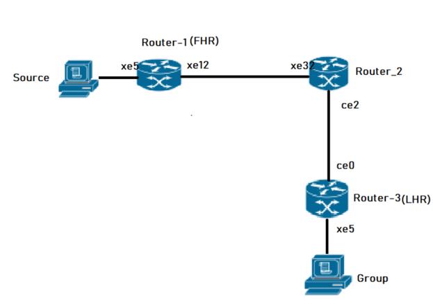
The topology consists of three primary OcNOS routers (Router-1, Router-2, and Router-3) forming a multicast domain.
• Router-2 serves as the Rendezvous Point (RP), configured with a Loopback interface (lo) address of 26.0.0.5 for IPv4 and 1201::8 for IPv6.
• Router-1 and Router-3 act as PIM Sparse Mode routers.
• The routers are interconnected via board interfaces (xe12, xe5, ce2, ce0).
• OSPF is used as the underlying IGP to provide unicast reachability between all routers and the RP.
PIM-SM Topology
Configuration
The following PIM Sparse Mode configurations apply to all PIM routers within the OcNOS multicast domain:
1. Enable global multicast routing for both IPv4 and IPv6 to allow the router to process and forward multicast packets across its interfaces.
(config)# ip multicast-routing
(config)# ipv6 multicast-routing
(config)# commit
2. Enable PIM Sparse Mode on physical interfaces to allow the exchange of PIM neighbor discovery and join/prune messages, facilitating the construction of the multicast tree.
(config)# interface xe12
(config-if)# ip pim sparse-mode
(config-if)# ipv6 pim sparse-mode
(config-if)# commit
3. Configure a static Rendezvous Point (RP) address to provide a consistent meeting point for sources and receivers throughout the PIM domain.
(config)# ip pim rp-address 26.0.0.5
(config)# ipv6 pim rp-address 1201::8
(config)# commit
Note: The configurations for Router-1 are shown as a sample; configurations for Router-2 and Router-3 are similar, ensuring interface-specific IP addresses and OSPF parameters are adjusted to match the topology.
Validation
To verify the PIM-SM configuration and operation, use the following show commands.
Verify PIM Interface Status. Check that PIM is active on the intended interfaces and verify the Designated Router (DR) election.
Router-1# show ip pim interface
Total number of PIM interfaces:2
Address Interface VIFindex Ver/ Nbr DR DR
Mode Count Prior
70.1.1.2 xe5 0 v2/S 0 1 70.1.1.2
20.1.1.2 xe12 2 v2/S 1 1 20.1.1.2
Router-1#show ipv6 pim interface
Total number of PIM interfaces:2
Interface VIFindex Ver/ Nbr DR
Mode Count Prior
xe5 2 v2/S 0 1
Address : fe80::5e07:58ff:fe28:b335
Global Address: 7001::2
DR : this system
xe12 0 v2/S 1 1
Address : fe80::5e07:58ff:fe28:b33c
Global Address: 2001::2
DR : fe80::5e07:58ff:fe6f:ff12
Verify PIM Neighbors
Ensure that PIM adjacency is established between neighboring routers to allow multicast control traffic flow.
router-2#show ip pim neighbor
Total number of PIM neighbors:2
Neighbor Interface Uptime/Expires Ver DR
Address Priority/Mode
30.1.1.2 ce2 00:37:56/00:01:19 v2 1 / DR
20.1.1.2 xe32 00:41:37/00:01:38 v2 1 / DR
router-2#show ipv6 pim neighbor
Total number of PIM neighbors:2
Neighbor Address Interface Uptime/Expires DR
Pri/Mode
fe80::5e07:58ff:fe28:b30a ce2 00:38:11/00:01:34 1 /
fe80::5e07:58ff:fe28:b33c xe32 00:47:00/00:01:34 1 /
router-2#sho ipv6 ospf neighbor
Total number of full neighbors: 2
OSPFv3 Process (100)
Neighbor ID Pri State Dead Time Interface Instance ID
6.6.6.6 1 Full/Backup 00:00:29 ce2 0
8.8.8.8 1 Full/DR 00:00:39 xe32 0
Verify RP Mappings Confirm that the router correctly identifies the static RP for the multicast group ranges.
router-2#show ip pim rp mapping
PIM Group-to-RP Mappings
Override RP cnt: 0
Group(s): 224.0.0.0/4, Static
RP: 26.0.0.5
Uptime: 00:48:23
Note: At Router-2, the show ipv6 pim rp mapping command shows that 1201::8 is the RP for all multicast groups ff00::8 and is statically configured. All other routers will have a similar output:
router-2#show ipv6 pim rp mapping
PIM Group-to-RP Mappings
Override RP cnt: 0
Group(s): ff00::/8, Static
RP: 1201::8
Uptime: 00:50:17
Verify Multicast Routing Table
The mroute table shows the active multicast entries, including the incoming interface (IIF) and outgoing interface list (OIL).
Note: At Router-2, the show ipv6 pim rp mapping command shows that 26.0.0.5 is the RP for all multicast groups in the range 224.0.0.0/4, and it is statically configured. All other routers display similar output:
Router-3#show ip mroute
IP Multicast Routing Table
Flags: I - Immediate Stat, T - Timed Stat, F - Forwarder installed
B - BIDIR
Timers: Uptime/Stat Expiry
Interface State: Interface (TTL)
(70.1.1.3, 225.1.1.5), uptime 00:02:36, stat expires 00:02:10
Owner PIM, Flags: TF
Incoming interface: ce0
Outgoing interface list:xe5(1)
router-2#sho ip pim rp mapping
PIM Group-to-RP Mappings
Override RP cnt: 0
Group(s): 224.0.0.0/4, Static
RP: 26.0.0.5
Uptime: 00:48:23
The show ipv6 pim mroute command displays the IPv6 multicast routing table. In this table, the following fields are defined:
R-E#show ipv6 pim mroute
IPv6 Multicast Routing Table
(*,*,RP) Entries: 0
G/prefix Entries: 0
(*,G) Entries: 5
(S,G) Entries: 5
(S,G,rpt) Entries: 5
FCR Entries: 0
(*, ff1e::1)
RP: 1001::1
RPF nbr: ::
RPF idx: None
Upstream State: JOINED
Local ................................
Joined ..j.............................
Asserted ................................
FCR:
At Router_E, eth2 is the incoming interface of the (*, G) entry, and eth1 is on the outgoing interface list of the
(*, G) entry. This means that there is a group member through eth1, and the RP is reachable through eth2.
The 0 position on this 32-bit index is for eth1 (as illustrated in the interface display above). The j on the 0 index indicates that the Join has come from eth1.
Since Router_C is the RP, and the root of this multicast tree, the show ip pim mroute command on Router_C shows RPF nbr as 0.0.0.0 and RPF idx as none.
Note: At Router-2, the show ipv6 pim rp mapping command shows that 1201::8 is the RP for all multicast groups ff00::8 and is statically configured. All other routers will have a similar output:
router-2#show ipv6 pim rp mapping
PIM Group-to-RP Mappings
Override RP cnt: 0
Group(s): ff00::/8, Static
RP: 1201::8
Uptime: 00:50:17
Implementation Example
Use Case: Enterprise Video Distribution An organization needs to stream high-definition training videos to multiple offices without saturating the network.
Solution: Implementing PIM-SM allows the video source to send a single stream to the RP. Only routers with employees actively watching the stream will join the shared tree and receive the traffic, ensuring efficient bandwidth utilization across the provider backbone.
Configuring Rendezvous Point Statically
In a Protocol Independent Multicast Sparse Mode (PIM-SM) domain, each multicast group must map to a single Rendezvous Point (RP). The RP acts as the root of the group-specific shared distribution tree (RPT). All routers within the PIM domain must know the RP address to correctly forward multicast Join and Register messages.
When you configure the RP statically, you manually define the RP IP address on every router in the PIM domain. Each router must maintain an identical RP-to-group mapping to ensure end-to-end multicast reachability.
Feature Characteristics
• Each multicast group requires exactly one RP address within the PIM domain.
• All routers must map the group to the same RP address.
• Configure the RP address on every router, including routers that:
• Do not have directly connected multicast sources.
• Do not have directly connected multicast receivers.
• The network can support multiple RPs.
• Each RP can serve different multicast groups.
• A single multicast group must map to only one RP.
• Static configuration does not use Auto-RP or BSR mechanisms.
• Routers do not dynamically learn RP information.
• Static RP configuration does not provide redundancy.
When configuring the RP statically, do the following:
• On every router, include the ip pim rp-address A.B.C.D statement even if a router does not have any source or group member attached to it
• Assign only one RP address for a multicast group in the PIM domain
Using the topology depicted in Figure 3-3, Router_C is the RP, and all routers are statically configured with RP information. Host_1 and Host_2 join group 224.0.1.3 for all the sources. They send the IGMP membership report to Subnet 1. Two routers are attached to Subnet 1, Router_E and Router_F; both have default DR priority on eth1. Since Router_E has a higher IP address on interface eth1, it becomes the Designated Router, and is responsible for sending Join messages to the RP (Router_C).
Benefits
• All routers use a fixed, administrator-defined RP address. The mapping does not change unless manually modified.
• Simple Deployment
• No dynamic RP advertisement or election mechanisms are required.
• The configuration eliminates RP discovery traffic.
• Suitable for Small and Stable Networks
• The approach is appropriate when:
• The number of multicast groups is limited.
• RP reassignment is infrequent.
• The network size is small.
Configuration
For configurations refer PIM Sparse Mode Configuration.
Validation
Enter the commands listed in this section to confirm the previous configurations.
RP Details
At Router_D, the show ip pim rp mapping command shows that 10.10.1.5 is the RP for all multicast groups 224.0.0.0/4, and is statically configured. All other routers will have a similar output:
R-D#show ip pim rp mapping
PIM Group-to-RP Mappings
Override RP cnt: 0
Group(s): 224.0.0.0/4, Static
RP: 10.10.1.5
Uptime: 00:19:31
R-D#
At Router_D, the show ipv6 pim rp mapping command shows that 1001::1 is the RP for all multicast groups ff00::8 and is statically configured. All other routers will have a similar output:
R-D#show ipv6 pim rp-mapping
PIM Group-to-RP Mappings
Override RP cnt: 0
Group(s): ff00::/8, Static
RP: 1001::1
Uptime: 01:21:47
Embedded RP Groups
Override RP cnt: 0At Router_D, use the show ip pim rp-hash command to display the selected RP for a specified group (224.0.1.3):
Router_D#show ipv6 pim rp-hash ff11::2
RP: 1222::2
Override RP cnt: 0At Router_D, use the show ipv6 pim rp-hash command to display the selected RP for a specified group (ff02::1).
Router_D#show ipv6 pim rp-hash
RP: 1001::1
Interface Details
The show ip pim interface command displays the interface details for Router_E, and shows that Router_E is the Designated Router on Subnet 1.
Router_E#show ip pim interface
Address Interface VIFindex Ver/ Nbr DR DR
Mode Count Prior
192.168.1.10 eth1 0 v2/S 1 1 192.168.1.10
172.16.1.10 eth2 2 v2/S 1 1 172.16.1.10
FOR IPV6
#show ipv6 pim neighbor
Total number of PIM neighbors:2
Neighbor Address Interface Uptime/Expires DR
Pri/Mode
fe80::eac5:7aff:fea8:7cb9 eth1 01:29:52/00:01:18 1 /
fe80::eac5:7aff:feb1:6b13 eth2 01:29:49/00:01:28 1 /
IP Multicast Routing Table
Note: The multicast routing table displays for an RP router are different from other routers.
The show ip pim mroute command displays the IP multicast routing table. In this table, the following fields are defined:
R-E#show ip pim mroute
(*,*,RP) Entries: 0
(*,G) Entries: 1
(S,G) Entries: 0
(S,G,rpt) Entries: 0
FCR Entries: 0
(*, 224.0.1.3)
RP: 10.10.1.5
RPF nbr: 172.16.1.2
RPF idx: eth2
Upstream State: JOINED
Local i...............................
Joined ................................
Asserted ................................
FCR:
The show ipv6 pim mroute command displays the IPv6 multicast routing table. In this table, the following fields are defined:
R-E#show ipv6 pim mroute
IPv6 Multicast Routing Table
(*,*,RP) Entries: 0
G/prefix Entries: 0
(*,G) Entries: 5
(S,G) Entries: 5
(S,G,rpt) Entries: 5
FCR Entries: 0
(*, ff1e::1)
RP: 1001::1
RPF nbr: ::
RPF idx: None
Upstream State: JOINED
Local ................................
Joined ..j.............................
Asserted ................................
FCR:
At Router_E, eth2 is the incoming interface of the (*, G) entry, and eth1 is on the outgoing interface list of the
(*, G) entry. This means that there is a group member through eth1, and the RP is reachable through eth2.
(*, G) entry. This means that there is a group member through eth1, and the RP is reachable through eth2.
The 0 position on this 32-bit index is for eth1 (as illustrated in the interface display above). The j on the 0 index indicates that the Join has come from eth1.
Since Router_C is the RP, and the root of this multicast tree, the show ip pim mroute command on Router_C shows RPF nbr as 0.0.0.0 and RPF idx as none.
R-C#show ip pim mroute
IP Multicast Routing Table
(*,*,RP) Entries: 0
(*,G) Entries: 1
(S,G) Entries: 0
(S,G,rpt) Entries: 0
FCR Entries: 0
(*, 224.0.1.3)
RP: 10.10.1.5
RPF nbr: 0.0.0.0
RPF idx: None
Upstream State: JOINED
Local ................................
Joined j...............................
Asserted ................................
FOR IPV6
#show ipv6 pim mroute
IPv6 Multicast Routing Table
(*,*,RP) Entries: 0
G/prefix Entries: 0
(*,G) Entries: 5
(S,G) Entries: 5
(S,G,rpt) Entries: 5
FCR Entries: 0
(*, ff1e::1)
RP: 1001::1
RPF nbr: ::
RPF idx: None
Upstream State: JOINED
Local ................................
Joined ..j.............................
Asserted ................................
FCR:
Implementations Example
Small Enterprise Multicast Deployment:
Scenario
An enterprise network deploys Protocol Independent Multicast Sparse Mode to support internal video distribution and software update streaming.
The multicast domain contains 8 routers and fewer than 10 multicast groups.
Design Decision:
• One router in the core acts as the RP.
• The administrator configures the same RP address on all routers.
• No redundancy is required.
• The topology remains stable.
Why Static RP is Appropriate:
• Limited number of routers.
• No requirement for RP failover.
• Low operational complexity.
• Predictable multicast forwarding behavior.
PIM Bootstrap Router
The Bootstrap Router (BSR) mechanism is a dynamic method for configuring Rendezvous Points (RP) within a Protocol Independent Multicast (PIM) Sparse Mode domain. It eliminates the need for manual, static RP assignments on every router, which is particularly critical for large or complex multicast networks. The BSR acts as a central distribution point, ensuring all routers in the domain learn the group-to-RP mappings necessary for multicast traffic forwarding.
Feature Description
In a PIM domain, the BSR mechanism utilizes a set of configured Candidate-BSRs (C-BSRs) and Candidate-RPs (C-RPs). Through an election process, the C-BSR with the highest priority value is elected as the BSR for the domain.
Once elected, the BSR performs the following technical functions:
• Candidacy Collection: C-RPs report their availability and the multicast groups they support to the elected BSR.
• RP Set Distribution: The BSR selects a subset of these C-RPs and distributes the group-to-RP mappings to all PIM routers via Bootstrap Messages (BSM).
• RP Election: When multiple RPs support the same group, routers select the RP with the lowest priority value. If priorities are equal, a hash function is applied to ensure a consistent RP choice across the domain.
Benefits
• Scalability: Automates RP distribution, making it ideal for large networking environments.
• Reduced Administrative Overhead: Eliminates repetitive manual configurations on every router when RPs change or fail.
• Fault Tolerance: If a primary RP fails, the BSR mechanism allows the network to dynamically switch to another Candidate-RP.
• Consistency: The hash mechanism ensures all routers in the PIM domain maintain an identical view of group-to-RP mappings.
Prerequisites
Before configuring BSR, ensure that the underlying Interior Gateway Protocol (IGP) such as OSPF or IS-IS is fully operational to provide reachability. Multicast routing must be enabled globally on all participating nodes.
• Essential Preliminary Configurations:
• Enable Multicast Routing: Both IPv4 and IPv6 multicast routing must be active.
• PIM Sparse Mode: PIM sparse-mode must be enabled on all participating interfaces.
• IGP Connectivity: Routers must have reachability to the loopback addresses used for BSR and RP candidacy.
Configuration
BSR configurations apply to PIM-enabled routers within the Service Provider MPLS or IP network.
Topology
The PIM Bootstrap Router (BSR) topology is designed to support dynamic Rendezvous Point (RP) discovery across a multicast domain. It consists of five key OcNOS routers interconnected via physical board interfaces to manage multicast traffic flows between sources and receivers.
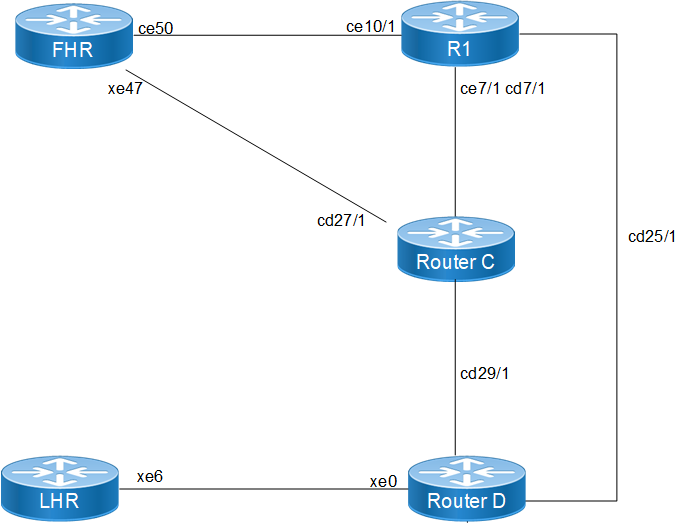
The following routers form the BSR domain, each performing a specific multicast function:
• First Hop Router: This node connects to the multicast source. It is responsible for encapsulating the source's data into PIM Register messages and sending them to the elected RP.
• Transit Node: A core router that provides a critical path between the source side (FHR) and the central multicast infrastructure.
• Candidate RP - Router_C: Configured as a Candidate RP (C-RP). It reports its candidacy to the BSR and, based on its priority (For example:priority 100), is elected to serve as the RP for a range of multicast groups.
• BSR & Candidate RP - Router_D: This node acts as the Candidate BSR (C-BSR). Once elected as the active BSR, it collects group-to-RP mappings from all C-RPs and broadcasts this information throughout the domain. It is also configured as a secondary C-RP.
• Last Hop Router: This node connects to the multicast receivers. It uses IGMP to learn about local receiver interest and then sends PIM Join messages toward the RP discovered via BSR messages.
Enable Multicast and PIM on All Nodes
1. Enable multicast routing and PIM sparse-mode on all interfaces across all routers in the domain to facilitate multicast traffic forwarding.
(config)# ip multicast-routing
(config)# ipv6 multicast-routing
(config-if)# ip pim sparse-mode
(config-if)# ipv6 pim sparse-mode
2. Configure Candidate BSR (on Router_D): Designate a router to participate in the BSR election. Configuring the priority allows for deterministic BSR selection; the highest priority value wins the election.
(config)# ip pim bsr-candidate lo 4 200
(config)# ipv6 pim bsr-candidate lo 4 200
3. Configure Candidate RP (on Router_C and Router_D): Identify routers that will serve as Rendezvous Points. Using a lower priority value ensures this node is preferred as the RP for the specified group range.
(config)# ip pim rp-candidate cd7/1 priority 100
(config)# ipv6 pim rp-candidate cd7/1 priority 100
Validation
Verify the dynamic RP and BSR status using the following show commands.
Verify BSR Information: Check which router has been elected as the BSR and its current priority.
LHR# show ip pim bsr-router
PIMv2 Bootstrap information
BSR address: 100.1.1.1
Uptime: 00:00:42, BSR Priority: 200, Hash mask length: 4
Role: Non-candidate BSR
State: Accept Preferred
For IPV6
#show ipv6 pim bsr-router
PIMv2 Bootstrap information
This system is the Bootstrap Router (BSR)
BSR address: 1001::1
Uptime: 00:00:04, BSR Priority: 64, Hash mask length: 12
Next bootstrap message in 00:00:03
Role: Candidate BSR
State: Elected BSR
Candidate RP: 3001::2(xe47)
Advertisement interval 4 seconds
Next C-RP advertisement in 00:00:03
Verify Group-to-RP Mappings: Ensure the routers have learned the RP for specific multicast groups through the BSR mechanism.
LHR# show ip pim rp mapping
PIM Group-to-RP Mappings
Group(s): 224.0.0.0/4
RP: 12.1.1.1
Info source: 100.1.1.1, via bootstrap, priority 100
For IPV6
# show ipv6 pim rp mapping
PIM Group-to-RP Mappings
Override RP cnt: 0
Group(s): ff00::/8, Static
RP: 1001::1
Uptime: 01:19:29
Embedded RP Groups:
Implementation Examples
Use Case: Large Enterprise Campus In a campus network with hundreds of VLANs, manually configuring a static RP on every access and distribution switch is error-prone. By implementing BSR, the administrator only needs to configure two core switches as C-BSRs and C-RPs. If the primary core switch fails, the BSR mechanism automatically promotes the secondary RP, ensuring uninterrupted video streaming or software distribution services.
Group to RP Mapping
Protocol Independent Multicast - Sparse Mode (PIM-SM) Group-to-Rendezvous Point (RP) mapping is a critical mechanism used in Any Source Multicast (ASM) domains to identify the RP for a specific multicast group. Each PIM-SM router maintains these mappings to determine how to join the shared tree for a group or where to send Register messages.
Feature Description
In a PIM-SM domain, routers learn the Group-to-RP mapping through various mechanisms such as Static RP, Auto-RP, or Bootstrap Router (BSR). OcNOS utilizes a defined algorithm to select the best RP from the available Group-to-RP mappings. This selection algorithm is designed to be consistent across the domain and does not prioritize based on the PIM mode or the specific mechanism (for example: Static vs. BSR) through which the mapping was learned.
Benefits
• Dynamic RP Discovery: Facilitates the automatic distribution of RP information throughout the PIM domain, reducing manual configuration overhead.
• Redundancy and Scalability: Supports multiple RP candidates and ensures all routers in the domain converge on the same RP for a specific group range.
• Flexible Group Management: Allows for granular control by mapping different multicast group ranges to different RPs.
Prerequisites
Before configuring Group-to-RP mappings, ensure the following base configurations are present on all participating routers:
• IP Multicast Routing: Multicast routing must be enabled globally on all PIM routers.
• PIM Sparse-Mode: PIM sparse-mode must be enabled on all transit and host-facing interfaces.
• Unicast Routing: A functional unicast routing protocol (for example: OSPF) must be configured to provide reachability between the LHR, FHR, and RP.
Configuration Prerequisites
The following configurations should be set up to align with the topology:
• Configure OSPF to ensure reachability across the 10.1.1.0/24, 20.1.1.0/24, 30.1.1.0/24, 40.1.1.0/24, and 50.1.1.0/24 networks.
• Enable PIM sparse-mode on the relevant interfaces for R1 (LHR), R2 (MID), R3 (RP), and R4 (FHR).
Configuration
Configure various nodes within the topology to set up an PIM-SM Group-to-RP Mapping Scenario.
Topology
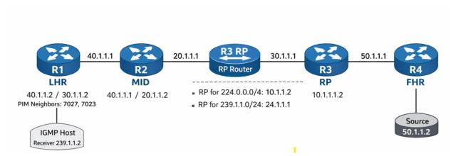
The topology consists of a linear path from the receiver to the source to demonstrate RP mapping and traffic flow.
• R1 (LHR): The Last Hop Router connected to the IGMP Host (Receiver 239.1.1.2).
• R2 (MID): A transit PIM router facilitating connectivity.
• R3 (RP): The Rendezvous Point for the domain, also acting as the Bootstrap Router (BSR).
• R4 (FHR): The First Hop Router connected to the Multicast Source (50.1.1.2).
Configuration Steps
The following PIM-SM Group-to-RP Mapping configurations apply to the RP and PIM-capable nodes within the Multicast network.
1. Enable global multicast routing and configure the router to act as a BSR candidate and RP candidate for specific group lists to facilitate dynamic mapping distribution.
(config)# ip multicast-routing
(config)# ip pim bsr-candidate lo
(config)# ip pim rp-candidate lo group-list MC
(config)# ip pim rp-candidate xe1
2. On the LHR and transit nodes, enable PIM on interfaces and verify the learned mappings via the Bootstrap mechanism to ensure proper group-to-RP association.
(config)# interface xe4
(config-if)# ip pim sparse-mode
(config)# interface ce0
(config-if)# ip pim sparse-mode
Running Configurations
Here is the sample configuration for LHR:
!
tfo Disable
errdisable cause stp-bpdu-guard
no feature telnet vrf management
no feature telnet
feature ssh vrf management
no feature ssh
feature dns relay
ip dns relay
ipv6 dns relay
feature ntp vrf management
ntp enable vrf management
!
ip vrf management
!
ip multicast-routing
!
ipv6 multicast-routing
!
interface cd1
!
interface cd3
!
interface ce0
ip address 40.1.1.2/24
ip pim sparse-mode
!
interface ce2
!
interface eth0
ip vrf forwarding management
ip address dhcp
!
interface lo
ip address 127.0.0.1/8
ipv6 address ::1/128
!
interface lo.management
ip vrf forwarding management
ip address 127.0.0.1/8
ipv6 address ::1/128
!
interface xe4
speed 10g
ip address 30.1.1.2/24
ipv6 address 3001::2/64
ipv6 router ospf area 0.0.0.0 instance-id 0
ip pim sparse-mode
ipv6 pim sparse-mode
!
interface xe5
!
interface xe18
ip address 60.1.1.1/24
ipv6 address 6001::1/64
ipv6 router ospf area 0.0.0.0 instance-id 0
ip pim sparse-mode
ipv6 pim sparse-mode
!
interface xe19
!
exit
!
router ospf 1
ospf router-id 5.5.5.5
network 5.5.5.5/32 area 0.0.0.0
network 10.1.1.0/24 area 0.0.0.0
network 30.1.1.0/24 area 0.0.0.0
network 40.1.1.0/24 area 0.0.0.0
network 60.1.1.0/24 area 0.0.0.0
!
router ipv6 ospf
router-id 1.1.1.1
!
port cd18 breakout 1X100g serdes 25g
port cd30 breakout 1X100g serdes 25g
port cd24 breakout 1X100g serdes 25g
port cd16 breakout 1X100g serdes 25g
port cd0 breakout 1X100g serdes 25g
tfo Disable
errdisable cause stp-bpdu-guard
no feature telnet vrf management
no feature telnet
feature ssh vrf management
no feature ssh
feature dns relay
ip dns relay
ipv6 dns relay
feature ntp vrf management
ntp enable vrf management
!
ip vrf management
!
ip multicast-routing
!
interface cd0/1
ip address 40.1.1.1/24
ip pim sparse-mode
!
interface cd1
!
interface cd2
!
interface cd3
!
interface cd4
!
interface cd5
!
!
interface cd16/1
ip address 20.1.1.2/24
ip pim sparse-mode
!
interface cd17
!
!
interface cd28
!
interface cd29
!
interface cd30/1
!
ip vrf forwarding management
ip address dhcp
!
interface lo
ip address 127.0.0.1/8
ipv6 address ::1/128
ipv6 pim sparse-mode
!
interface lo.management
ip vrf forwarding management
ip address 127.0.0.1/8
ipv6 address ::1/128
!
exit
!
router ospf 1
ospf router-id 1.1.1.1
network 20.1.1.0/24 area 0.0.0.0
network 40.1.1.0/24 area 0.0.0.0
!
line vty 0 16
exec-timeout 0 0
!
!
end
RP
!
qos enable
!
ip access-list standard MC
permit 239.1.1.0/24
!
ipv6 access-list standard MC1
permit ff03::/64
!
hostname rp
tfo Disable
errdisable cause stp-bpdu-guard
no feature telnet vrf management
no feature telnet
feature ssh vrf management
no feature ssh
feature dns relay
ip dns relay
ipv6 dns relay
feature ntp vrf management
ntp enable vrf management
!
ip vrf management
!
ip multicast-routing
!
ipv6 multicast-routing
!
ip pim bsr-candidate lo
ip pim rp-candidate lo group-list MC
ip pim rp-candidate xe1
!
ipv6 pim bsr-candidate lo
ipv6 pim rp-candidate lo group-list MC1
ipv6 pim rp-candidate xe1
!
interface ce1
!
interface ce2
!
interface ce3
!
interface ce4
ip address 20.1.1.1/24
ip pim sparse-mode
!
interface ce5
!
interface ce6
!
interface ce7
!
interface ce8
!
interface ce9
!
interface ce10
!
interface ce23
!
ip vrf forwarding management
ip address dhcp
!
interface lo
ip address 127.0.0.1/8
ip address 24.1.1.1/24 secondary
ipv6 address ::1/128
ipv6 address 1111::1/64
ipv6 router ospf area 0.0.0.0 instance-id 0
ip pim sparse-mode
ipv6 pim sparse-mode
!
interface lo.management
ip vrf forwarding management
ip address 127.0.0.1/8
ipv6 address ::1/128
!
interface xe0
!
interface xe1
speed 10g
ip address 10.1.1.2/24
ipv6 address 1001::2/64
ipv6 router ospf area 0.0.0.0 instance-id 0
ip pim sparse-mode
ipv6 pim sparse-mode
!
interface xe2
ip address 30.1.1.1/24
ipv6 address 3001::1/64
ipv6 router ospf area 0.0.0.0 instance-id 0
ip pim sparse-mode
ipv6 pim sparse-mode
!
interface xe3
!
exit
!
router ospf 1
ospf router-id 6.6.6.6
network 6.6.6.6/32 area 0.0.0.0
network 10.1.1.0/24 area 0.0.0.0
network 20.1.1.0/24 area 0.0.0.0
network 24.1.1.1/32 area 0.0.0.0
network 30.1.1.0/24 area 0.0.0.0
!
router ipv6 ospf
router-id 2.2.2.2
!
!
end
FHR
!
qos enable
!
hostname FHR
tfo Disable
errdisable cause stp-bpdu-guard
no feature telnet vrf management
no feature telnet
feature ssh vrf management
no feature ssh
feature dns relay
ip dns relay
ipv6 dns relay
feature ntp vrf management
ntp enable vrf management
!
vlan database
vlan-reservation 4041-4094
!
ip vrf management
!
ip multicast-routing
!
ipv6 multicast-routing
!
interface ce49
!
interface ce50
!
interface ce51
!
interface ce52
!
interface ce53
!
interface ce54
!
interface eth0
ip vrf forwarding management
ip address dhcp
!
interface lo
ip address 127.0.0.1/8
ipv6 address ::1/128
!
interface lo.management
ip vrf forwarding management
ip address 127.0.0.1/8
ipv6 address ::1/128
!
interface xe1
!
interface xe2
!
interface xe3
!
interface xe4
!
interface xe23
ip address 50.1.1.1/24
ipv6 address 5001::1/64
ipv6 router ospf area 0.0.0.0 instance-id 0
ip pim sparse-mode
ipv6 pim sparse-mode
!
interface xe24
!
interface xe25
speed 10g
ip address 10.1.1.1/24
ipv6 address 1001::1/64
ipv6 router ospf area 0.0.0.0 instance-id 0
ipv6 mld version 2
ip pim sparse-mode
ipv6 pim sparse-mode
!
interface xe42
!
interface xe43
!
exit
!
router ospf 1
ospf router-id 8.8.8.8
network 6.6.6.6/32 area 0.0.0.0
network 8.8.8.8/32 area 0.0.0.0
network 10.1.1.0/24 area 0.0.0.0
network 30.1.1.0/24 area 0.0.0.0
network 50.1.1.0/24 area 0.0.0.0
!
router ipv6 ospf
router-id 3.3.3.3
!
!
end
Validation
Verify the PIM neighbor status on the LHR (R1)
LHR#show ip pim neighbor
Total number of PIM neighbors:2
Neighbor Interface Uptime/Expires Ver DR
Address Priority/Mode
40.1.1.1 ce0 00:02:05/00:01:36 v2 1 /
30.1.1.1 xe4 01:35:46/00:01:32 v2 1 /
Verify RP Mappings
Check the learned RP information on the LHR (R1). The output shows the group ranges and the associated RP addresses learned via BSR
LHR#show ip pim rp mapping
PIM Group-to-RP Mappings
Group(s): 224.0.0.0/4
RP: 10.1.1.2
Info source: 24.1.1.1, via bootstrap, priority 192
Uptime: 00:16:55, expires: 00:01:35
Group(s): 239.1.1.0/24
RP: 24.1.1.1
Info source: 24.1.1.1, via bootstrap, priority 192
Uptime: 00:19:41, expires: 00:01:35
Override RP cnt: 0
LHR#sh ip igmp groups
IGMP Instance wide G-Recs Count is: 0
LHR#show ip igmp groups
IGMP Instance wide G-Recs Count is: 1
IGMP Connected Group Membership
Group Address Interface Uptime Expires State Last Reporte
r
239.1.1.2 xe18 00:00:01 00:04:17 Active 60.1.1.2
LHR#show ip igmp groups de
IGMP Instance wide G-Recs Count is: 1
IGMP Connected Group Membership Details
Flags: (M - SSM Mapping, R - Remote, L - Local,
SG - Static Group, SS - Static Source)
Interface: xe18
Group: 239.1.1.2
Flags: R
Uptime: 00:00:02
Group mode: Exclude (Expires: 00:04:17)
State: Active
Last reporter: 60.1.1.2
Source list is empty
Verify Multicast Route (mroute) Table
The RPF neighbor should point toward the RP.
LHR#show ip pim mr
IP Multicast Routing Table
(*,*,RP) Entries: 0
G/prefix Entries: 0
(*,G) Entries: 1
(S,G) Entries: 0
(S,G,rpt) Entries: 0
FCR Entries: 0
(*, 239.1.1.2)
RP: 24.1.1.1
RPF nbr: 30.1.1.1
RPF idx: xe4
Upstream State: JOINED
Local ..i.............................
Joined ................................
Asserted ................................
FCR:
LHR#show ip mr
IP Multicast Routing Table
Flags: I - Immediate Stat, T - Timed Stat, F - Forwarder installed
B - BIDIR
Timers: Uptime/Stat Expiry
Interface State: Interface (TTL)
(50.1.1.2, 239.1.1.2), uptime 00:00:39, stat expires 00:02:52
Owner PIM, Flags: TF
Incoming interface: xe4
Outgoing interface list:
xe18 (1)
LHR#show ip pim mr
IP Multicast Routing Table
(*,*,RP) Entries: 0
G/prefix Entries: 0
(*,G) Entries: 1
(S,G) Entries: 0
(S,G,rpt) Entries: 0
FCR Entries: 1
(*, 239.1.1.2)
RP: 24.1.1.1
RPF nbr: 30.1.1.1
RPF idx: xe4
Upstream State: JOINED
Local ..i.............................
Joined ................................
Asserted ................................
FCR:
Source: 50.1.1.2
Outgoing ..o.............................
KAT timer running, 168 seconds remaining
Packet count 1
Verify Traffic Rate
Confirm multicast traffic is flowing from the incoming interface to the outgoing interface connected to the receiver.
LHR# show interface counters rate mbps
+-------------------+--------------+-------------+--------------+-------------+
| Interface | Rx mbps | Rx pps | Tx mbps | Tx pps |
+-------------------+--------------+-------------+--------------+-------------+
xe4 20.85 39479 0.00 0
xe18 0.00 0 20.85 39481
Implementation Examples
Enterprise Multicast Isolation A corporation needs to separate internal training video traffic from general background multicast.
By configuring two different RPs and using BSR group-lists, the network engineer maps the training range (239.1.1.0/24) to a high-performance RP while keeping general traffic on a default RP. This optimizes traffic flow and provides administrative control over different multicast streams.
Anycast RP for IPv4 and IPv6
PIM Anycast Rendezvous Point (RP) is a networking solution designed to provide redundancy and load sharing for the RP in a Protocol Independent Multicast - Sparse Mode (PIM-SM) domain. By configuring multiple RPs with the same Anycast IP address, the network ensures high availability; if one RP fails, multicast traffic automatically reroutes to the topologically closest RP based on unicast routing metrics.
Feature Characteristics
• Redundancy and Load Sharing: Multiple RPs are configured with the same Anycast IP address, allowing the network to failover to a secondary RP if the primary becomes unreachable.
• Dual-Stack Support: Supports both IPv4 and IPv6 Anycast RP configurations.
• MSDP-less Anycast: Utilizes PIM anycast-rp commands to define the set of routers participating in the Anycast RP set, eliminating the need for Multicast Source Discovery Protocol (MSDP) in many scenarios.
• Static RP Mapping: Routers in the PIM domain use static configuration to point to the Anycast RP address.
Benefits
• Efficient Traffic Control: Multicast traffic follows the shortest path to the nearest available RP, reducing latency and network congestion.
• Enhanced Reliability: If one RP node fails, the underlying unicast routing protocol (e.g., OSPF) automatically redirects traffic to the next nearest RP node.
• Scalability: Simplifies the management of large multicast domains by providing a consistent RP address for all PIM-enabled routers.
• Improved Performance: Distributed RP load prevents a single router from becoming a bottleneck for multicast register messages and join requests.
Configuration
Before configuring Anycast RP, ensure the following foundational protocols are active on all participating nodes:
• IP Multicast Routing: Must be enabled globally for both IPv4 and IPv6.
• Unicast Routing: OSPF or another IGP must be configured to provide reachability for the RP addresses and loopbacks.
• PIM Sparse-Mode: Enabled on all transit and host-facing interfaces.
Topology
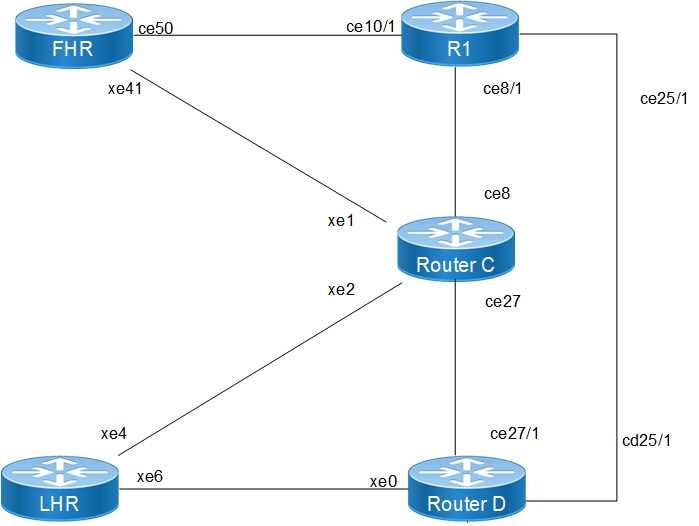
The Anycast RP validation network is designed to demonstrate high availability and path optimization for both IPv4 and IPv6 multicast traffic across a service provider fabric. The topology is categorized into the following functional roles:
• FHR : This node serves as the entry point for multicast sources within the domain. It utilizes multiple paths to the core, specifically connecting to RP-1 via interface ce50 and the intermediate node via interface xe41.
• RP-1 : Functions as the primary Rendezvous Point for its topologically local segment. It is configured with a unique physical loopback 10.10.10.1 for peer synchronization and the shared Anycast RP address 10.10.10.10.
• RP-2 : Functions as a redundant Rendezvous Point, sharing the Anycast RP address 10.10.10.10. It provides load sharing and immediate failover capabilities should RP-1 become unreachable.
• Intermediate Transit Node : Acts as a core switching/routing element that maintains PIM neighbor relationships with the FHR, LHR, and both Anycast RPs. It ensures that Join/Prune messages are routed to the nearest available RP based on unicast IGP metrics.
• LHR : This node acts as the egress point for multicast subscribers and receivers. It manages IGMP/MLD group memberships on its host-facing interface xe18 and builds the shortest-path tree toward the Anycast RP address.
TAnycast RP Topology
The following PIM Anycast RP configurations applies to RP nodes and PIM domain routers within the OcNOS network.
1. Enable multicast routing globally on all routers to allow the processing of PIM join/prune messages and the maintenance of the multicast forwarding table.
(config)# ip multicast-routing
(config)# ipv6 multicast-routing
(config)# commit
2. Statically define the RP address on all routers in the PIM domain. This Anycast address (10.10.10.10 or 2001:db8:100::10) must be the same on every node to ensure a unified RP view.
(config)# ip pim rp-address 10.10.10.10
(config)# ipv6 pim rp-address 2001:db8:100::10
3. On the designated RP nodes, configure the Anycast RP membership. Each RP must list itself and its peers using its unique physical loopback addresses to facilitate register message synchronization.
(config)# ip pim anycast-rp 10.10.10.10 10.10.10.1
(config)# ip pim anycast-rp 10.10.10.10 10.10.10.2
(config)# ipv6 pim anycast-rp 2001:db8:100::10 2001:db8:100::1
(config)# ipv6 pim anycast-rp 2001:db8:100::10 2001:db8:100::2
4. Configure the loopback interfaces on the RP nodes with both the unique physical address and the shared Anycast address to support PIM identification and reachability.
(config)# interface lo
(config-if)# ip address 10.10.10.1/32 secondary
(config-if)# ip address 10.10.10.10/32 secondary
(config-if)# ipv6 address 2001:db8:100::1/128
(config-if)# ipv6 address 2001:db8:100::10/128
(config-if)# ip pim sparse-mode
(config-if)# ipv6 pim sparse-mode
Validation
Verify the PIM Anycast RP configuration:
Verify RP Mapping and Anycast Members Use the show ip pim rp mapping command on the RP nodes to confirm the Anycast-RP members are correctly identified.
show ip pim rp mapping
PIM Group-to-RP Mappings
Anycast-RP 10.10.10.10 members :
10.10.10.1 10.10.10.2
Group(s): 224.0.0.0/4, Static
RP: 10.10.10.10
Verify PIM Neighbor States Ensure all routers have established PIM adjacencies over their respective interfaces.
show ip pim neighbor
Total number of PIM neighbors:4
Neighbor Interface Uptime/Expires Ver DR
190.1.1.1 xe2 00:37:23/00:01:23 v2 1
11.1.1.1 xe1 00:37:32/00:01:16 v2 1
Verify Multicast Routing Table (mroute) Check the mroute table on the LHR to ensure the (*, G) entries point toward the Anycast RP.
show ip pim mroute
(*, 225.1.1.1)
RP: 10.10.10.10
RPF nbr: 15.1.1.1
RPF idx: xe6
Upstream State: JOINED
Implementation Examples
Use Case: ISP Multicast Content Delivery An ISP providing IPTV services needs to ensure that the stream remains uninterrupted even if a core RP node fails. By deploying Anycast RP on two geographically separate routers, the ISP achieves automatic redundancy. Receivers will join via the topologically closest RP, optimizing bandwidth while providing a robust backup solution.