IS-IS IPv4
This chapter contains basic IS-IS (Intermediate System to Intermediate System) configuration examples.
Enable IS-IS on an Interface
This example shows the minimum configuration required for enabling IS-IS on an interface. R1 and R2 are two routers in the ABC instance connecting to the network 10.10.10.0/24. After enabling IS-IS on an interface, create a routing instance, and specify the Network Entity Title (NET). IS-IS explicitly specifies a NET to begin routing. NET is comprised of the area address and the system ID of the router.
Topology

Basic IS-IS Topology
Configuration
R1
#configure terminal | Enter configure mode. |
(config)#interface eth1 | Enter interface mode. |
(config)#ip address 21.21.21.2/24 | Configure IP address on interface. |
(config-if)#ip router isis ABC | Enable IS-IS routing on an interface for area 49 (ABC). |
(config-if)#exit | Exit interface mode. |
(config)#router isis ABC | Create an IS-IS routing instance for area 49 (ABC). |
(config-router)#is-type level-2-only | Configure instance as level-2-only routing. |
(config-router)#net 49.0000.0000.0001.00 | Set a Network Entity Title for this instance, specifying the area address and the system ID. |
(config-router)#commit | Commit candidate configuration to the running configuration |
R2
#configure terminal | Enter configure mode. |
(config)#interface eth1 | Enter interface mode. |
(config)#ip address 21.21.21.1/24 | Configure IP address on interface. |
(config-if)#ip router isis ABC | Enable IS-IS routing on an interface for area 49 (ABC). |
(config-if)#commit | Commit candidate configuration to the running configuration |
(config-if)#exit | Exit interface mode. |
(config)#router isis ABC | Create an IS-IS routing instance for area 49 (ABC). |
(config-router)#is-type level-2-only | Configure instance as level-2-only routing. |
(config-router)#net 49.0000.0000.0002.00 | Set a Network Entity Title for this instance, specifying the area address and the system ID. |
Validation
R1#show clns neighbors
Total number of L1 adjacencies: 0
Total number of L2 adjacencies: 1
Total number of adjacencies: 1
Tag ABC: VRF : default
System Id Interface SNPA State Holdtime Type Protocol
0000.0000.0002 eth1 5254.002a.230a Up 24 L2 IS-IS
R2#show clns neighbors
Total number of L1 adjacencies: 0
Total number of L2 adjacencies: 1
Total number of adjacencies: 1
Tag ABC: VRF : default
System Id Interface SNPA State Holdtime Type Protocol
0000.0000.0001 eth1 5254.00dc.0b76 Up 6 L2 IS-IS
R1#show clns is-neighbors
Tag ABC: VRF : default
System Id Interface State Type Priority Circuit Id
0000.0000.0002 eth1 Up L2 64 0000.0000.0001.01
R2#show clns is-neighbors
Tag ABC: VRF : default
System Id Interface State Type Priority Circuit Id
0000.0000.0001 eth1 Up L2 64 0000.0000.0001.01
R1#show isis interface
eth1 is up, line protocol is up
Routing Protocol: IS-IS (ABC)
Network Type: Broadcast
Circuit Type: level-1-2
Local circuit ID: 0x01
Extended Local circuit ID: 0x00000003
Local SNPA: 5254.00dc.0b76
IP interface address:
21.21.21.2/24
IPv6 interface address:
fe80::5054:ff:fedc:b76/64
Level-2 Metric: 10/10, Priority: 64, Circuit ID: 0000.0000.0001.01
Number of active level-2 adjacencies: 1
Level-2 LSP MTU: 1492
Next IS-IS LAN Level-2 Hello in 0 milliseconds
R2#show isis interface
eth1 is up, line protocol is up
Routing Protocol: IS-IS (ABC)
Network Type: Broadcast
Circuit Type: level-1-2
Local circuit ID: 0x01
Extended Local circuit ID: 0x00000003
Local SNPA: 5254.002a.230a
IP interface address:
21.21.21.1/24
IPv6 interface address:
fe80::5054:ff:fe2a:230a/64
Level-2 Metric: 10/10, Priority: 64, Circuit ID: 0000.0000.0001.01
Number of active level-2 adjacencies: 1
Level-2 LSP MTU: 1492
Next IS-IS LAN Level-2 Hello in 1 seconds
R1#show ip isis route
Codes: C - connected, E - external, L1 - IS-IS level-1, L2 - IS-IS level-2
ia - IS-IS inter area, D - discard, e - external metric
** - invalid
Tag ABC: VRF : default
Destination Metric Next-Hop Interface Tag
C 21.21.21.0/24 10 -- eth1 0
R2#show ip isis route
Codes: C - connected, E - external, L1 - IS-IS level-1, L2 - IS-IS level-2
ia - IS-IS inter area, D - discard, e - external metric
** - invalid
Tag ABC: VRF : default
Destination Metric Next-Hop Interface Tag
C 21.21.21.0/24 10 -- eth1 0
R1#show isis topology
Tag ABC: VRF : default
IS-IS paths to level-2 routers
System Id Metric Next-Hop Interface SNPA
0000.0000.0001 --
0000.0000.0002 10 0000.0000.0002 eth1 5254.002a.230a
R2#show isis topology
Tag ABC: VRF : default
IS-IS paths to level-2 routers
System Id Metric Next-Hop Interface SNPA
0000.0000.0001 10 0000.0000.0001 eth1 5254.00dc.0b76
0000.0000.0002 --
R1#show isis database
Tag ABC: VRF : default
IS-IS Level-2 Link State Database:
LSPID LSP Seq Num LSP Checksum LSP Holdtime ATT/P/OL
0000.0000.0001.00-00* 0x00000009 0x6C2D 980 0/0/0
0000.0000.0001.01-00* 0x00000003 0x1DBB 980 0/0/0
0000.0000.0002.00-00 0x0000000A 0x5444 980 0/0/0
R2#show isis database
Tag ABC: VRF : default
IS-IS Level-2 Link State Database:
LSPID LSP Seq Num LSP Checksum LSP Holdtime ATT/P/OL
0000.0000.0001.00-00 0x00000009 0x6C2D 942 0/0/0
0000.0000.0001.01-00 0x00000003 0x1DBB 942 0/0/0
0000.0000.0002.00-00* 0x0000000A 0x5444 944 0/0/0
Set Priority
This example describes how to set the priority for an interface. Set a high priority for a router to make it the Designated IS (DIS). Router R2 is configured to have a priority of 125, this is higher than the default priority (64) of R1. This makes R2 the DIS.
Topology
Set IS-IS Priority
Configuration
R1
(config)#interface eth1 | Enter interface mode. |
(config-if)#ip router isis ABC | Enable IS-IS routing on an interface for area 49 (ABC). |
(config)#ip address 21.21.21.2/24 | Configure IP address on interface. |
(config-if)#commit | Commit candidate configuration to the running configuration |
(config-if)#exit | Exit interface mode. |
(config)#router isis ABC | Create an IS-IS routing instance for area 49 (ABC). |
(config-router)#is-type level-2-only | Configure instance as level-2-only routing. |
(config-router)#net 49.0000.0000.0001.00 | Set a Network Entity Title for this instance, specifying the area address and the system ID. |
(config-router)#commit | Commit candidate configuration to the running configuration |
R2
(config)#interface eth1 | Enter interface mode. |
(config)#ip address 21.21.21.1/24 | Configure IP address on interface. |
(config-if)#ip router isis ABC | Enable IS-IS routing on an interface for area 49 (ABC). |
(config-if)#isis priority 125 | Specify the router priority to a higher priority (125) to make R2 the designated IS (DIS). |
(config-if)#commit | Commit candidate configuration to the running configuration |
(config-if)#exit | Exit interface mode. |
(config)#router isis ABC | Create an IS-IS routing instance for area 49 (ABC). |
(config-router)#is-type level-2-only | Configure instance as level-2-only routing. |
(config-router)#net 49.0000.0000.0002.00 | Set a Network Entity Title for this instance, specifying the area address and the system ID. |
Validation
R1#show clns neighbors
Total number of L1 adjacencies: 0
Total number of L2 adjacencies: 1
Total number of adjacencies: 1
Tag ABC: VRF : default
System Id Interface SNPA State Holdtime Type Protocol
0000.0000.0002 eth1 5254.002a.230a Up 6 L2 IS-IS
R2#show clns neighbors
Total number of L1 adjacencies: 0
Total number of L2 adjacencies: 1
Total number of adjacencies: 1
Tag ABC: VRF : default
System Id Interface SNPA State Holdtime Type Protocol
0000.0000.0001 eth1 5254.00dc.0b76 Up 21 L2 IS-IS
R1#show clns is-neighbors
Tag ABC: VRF : default
System Id Interface State Type Priority Circuit Id
0000.0000.0002 eth1 Up L2 125 0000.0000.0002.01
R2#show clns is-neighbors
Tag ABC: VRF : default
System Id Interface State Type Priority Circuit Id
0000.0000.0001 eth1 Up L2 64 0000.0000.0002.01
R1#show isis interface
eth1 is up, line protocol is up
Routing Protocol: IS-IS (ABC)
Network Type: Broadcast
Circuit Type: level-1-2
Local circuit ID: 0x01
Extended Local circuit ID: 0x00000003
Local SNPA: 5254.00dc.0b76
IP interface address:
21.21.21.2/24
IPv6 interface address:
fe80::5054:ff:fedc:b76/64
Level-2 Metric: 10/10, Priority: 64, Circuit ID: 0000.0000.0002.01
Number of active level-2 adjacencies: 1
Level-2 LSP MTU: 1492
Next IS-IS LAN Level-2 Hello in 1 seconds
R2#show isis interface
eth1 is up, line protocol is up
Routing Protocol: IS-IS (ABC)
Network Type: Broadcast
Circuit Type: level-1-2
Local circuit ID: 0x01
Extended Local circuit ID: 0x00000003
Local SNPA: 5254.002a.230a
IP interface address:
21.21.21.1/24
IPv6 interface address:
fe80::5054:ff:fe2a:230a/64
Level-2 Metric: 10/10, Priority: 125, Circuit ID: 0000.0000.0002.01
Number of active level-2 adjacencies: 1
Level-2 LSP MTU: 1492
Next IS-IS LAN Level-2 Hello in 737 milliseconds
Dynamic hostname
This example shows how to configure Dynamic Hostname for an ISIS instance. Dynamic hostname is the method of mapping name-to-systemID. It allows the routing protocol to advertise symbolic names in the IS-IS PDUs. This is done by the addition of a new TLV which allows the IS-IS routers to include the name-to-systemID mapping data in their LSPs. This allows for simple and reliable transport of name mapping across IS-IS networks. Dynamic hostname can be either the hostname of the node or the tag of the configured ISIS instance.
Note: Dynamic-hostname has to be configured on all nodes for it to take effect.
Topology
Basic dynamic hostname topology
Configuration
R1
(config)#interface eth1 | Enter interface mode. |
(config-if)#ip router isis ABC | Enable IS-IS routing on an interface for area 49 (ABC). |
(config)#ip address 21.21.21.2/24 | Configure IP address on interface. |
(config-if)#commit | Commit candidate configuration to the running configuration |
(config-if)#exit | Exit interface mode. |
(config)#router isis ABC | Create an IS-IS routing instance for area 49 (ABC). |
(config-router)#is-type level-2-only | Configure instance as level-2-only routing. |
(config-router)#net 49.0000.0000.0001.00 | Set a Network Entity Title for this instance, specifying the area address and the system ID. |
(config-router)#dynamic-hostname | Configure the hostname to be advertised for an ISIS instance. |
(config-router)#commit | Commit candidate configuration to the running configuration |
R2
(config)#interface eth1 | Enter interface mode. |
(config)#ip address 21.21.21.1/24 | Configure IP address on interface. |
(config-if)#ip router isis ABC | Enable IS-IS routing on an interface for area 49 (ABC). |
(config-if)#commit | Commit candidate configuration to the running configuration |
(config-if)#exit | Exit interface mode. |
(config)#router isis ABC | Create an IS-IS routing instance for area 49 (ABC). |
(config-router)#is-type level-2-only | Configure instance as level-2-only routing. |
(config-router)#net 49.0000.0000.0002.00 | Set a Network Entity Title for this instance, specifying the area address and the system ID. |
(config-router)#dynamic-hostname | Configure the hostname to be advertised for an ISIS instance. |
(config-router)#commit | Commit candidate configuration to the running configuration |
Validation
R1#show clns neighbors
Total number of L1 adjacencies: 0
Total number of L2 adjacencies: 1
Total number of adjacencies: 1
Tag ABC: VRF : default
System Id Interface SNPA State Holdtime Type Protocol
R2 eth1 5254.002a.230a Up 28 L2 IS-IS
R2#show clns neighbors
Total number of L1 adjacencies: 0
Total number of L2 adjacencies: 1
Total number of adjacencies: 1
Tag ABC: VRF : default
System Id Interface SNPA State Holdtime Type Protocol
R1 eth1 5254.00dc.0b76 Up 7 L2 IS-IS
R1#show clns is-neighbors
Tag ABC: VRF : default
System Id Interface State Type Priority Circuit Id
R2 eth1 Up L2 64 0000.0000.0001.01
R2#show clns is-neighbors
Tag ABC: VRF : default
System Id Interface State Type Priority Circuit Id
R1 eth1 Up L2 64 0000.0000.0001.01
R1#show isis topology
Tag ABC: VRF : default
IS-IS paths to level-2 routers
System Id Metric Next-Hop Interface SNPA
R1 --
R2 10 R2 eth1 5254.002a.230a
R2#show isis topology
Tag ABC: VRF : default
IS-IS paths to level-2 routers
System Id Metric Next-Hop Interface SNPA
R1 10 R1 eth1 5254.00dc.0b76
R2 --
R1#show isis database
Tag ABC: VRF : default
IS-IS Level-2 Link State Database:
LSPID LSP Seq Num LSP Checksum LSP Holdtime ATT/P/OL
R1.00-00 * 0x0000000B 0x1D6B 1170 0/0/0
R1.01-00 * 0x00000004 0x1BBC 538 0/0/0
R2.00-00 0x0000000C 0x0D79 1166 0/0/0
R2#show isis database
Tag ABC: VRF : default
IS-IS Level-2 Link State Database:
LSPID LSP Seq Num LSP Checksum LSP Holdtime ATT/P/OL
R1.00-00 0x0000000B 0x1D6B 1078 0/0/0
R1.01-00 0x00000004 0x1BBC 445 0/0/0
R2.00-00 * 0x0000000C 0x0D79 1075 0/0/0
Redistribute Routes into IS-IS
In this example, the configuration causes OSPF routes to be imported into the IS-IS routing table, and advertised into the ABC instance.
Topology
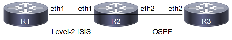
Redistribute Routes Into IS-IS
Configuration
R1
(config)#interface eth1 | Enter interface mode. |
(config-if)#ip router isis ABC | Enable IS-IS routing on an interface for area 49 (ABC). |
(config)#ip address 21.21.21.2/24 | Configure IP address on interface. |
(config-if)#commit | Commit candidate configuration to the running configuration |
(config-if)#exit | Exit interface mode. |
(config)#router isis ABC | Create an IS-IS routing instance for area 49 (ABC). |
(config-router)#is-type level-2-only | Configure instance as level-2-only routing. |
(config-router)#net 49.0000.0000.0001.00 | Set a Network Entity Title for this instance, specifying the area address and the system ID. |
(config-router)#dynamic-hostname | Configure the hostname to be advertised for an ISIS instance. |
(config-router)#commit | Commit candidate configuration to the running configuration |
R2
(config)#interface eth1 | Enter interface mode. |
(config-if)#ip address 21.21.21.1/24 | Configure IP address on interface. |
(config-if)#commit | Commit candidate configuration to the running configuration |
(config-if)#ip router isis ABC | Enable IS-IS routing on an interface for area 49 (ABC). |
(config-if)#commit | Commit candidate configuration to the running configuration |
(config-if)#exit | Exit interface mode. |
(config)#interface eth2 | Enter interface mode. |
(config-if)#ip address 31.31.31.1/24 | Configure IP address on interface. |
(config-if)#commit | Commit candidate configuration to the running configuration |
(config-if)#exit | Exit interface mode. |
(config)#router isis ABC | Create an IS-IS routing instance for area 49 (ABC). |
(config-router)#is-type level-2-only | Configure instance as level-2-only routing. |
(config-router)#net 49.0000.0000.0002.00 | Set a Network Entity Title for this instance, specifying the area address and the system ID. |
(config-router)#redistribute ospf | Specify redistributing routes from other routing protocol (OSPF) into IS-IS. |
(config-router)#dynamic-hostname | Configure the hostname to be advertised for an ISIS instance. |
(config-router)#commit | Commit candidate configuration to the running configuration |
(config-router)#exit | Exit interface mode. |
(config)#interface lo | Configure interface lo |
(config-if)#ip address 2.2.2.2/32 secondary | Configure secondary IP address to loopback interface |
(config-if)#commit | Commit candidate configuration to the running configuration |
(config-if)#exit | Exit interface mode. |
(config)#router ospf 100 | Configure OSPF routing process and specify the tag (100) which uniquely identifies the routing process |
(config-router)#ospf router-id 2.2.2.2 | Specify a Router ID (2.2.2.2) for the OSPF routing process. |
(config-router)#network 2.2.2.2/32 area 0.0.0.0 | Advertising 2.2.2.2 network |
(config-router)#network 31.31.31.0/24 area 0.0.0.0 | Advertising 31 network |
(config-router)#commit | Commit candidate configuration to the running configuration |
(config-router)#exit | Exit router mode. |
R3
(config)#interface eth2 | Enter interface mode. |
(config-if)#ip address 31.31.31.2/24 | Configure IP address on interface. |
(config-if)#commit | Commit candidate configuration to the running configuration |
(config-if)#exit | Exit interface mode. |
(config)#interface lo | Configure interface lo |
(config-if)#ip address 3.3.3.3/32 secondary | Configure secondary IP address to loopback interface |
(config-if)#commit | Commit candidate configuration to the running configuration |
(config-if)#exit | Exit interface mode. |
(config)#router ospf 100 | Configure OSPF routing process and specify the tag (100) which uniquely identifies the routing process |
(config-router)#ospf router-id 3.3.3.3 | Specify a Router ID (3.3.3.3) for the OSPF routing process. |
(config-router)#network 3.3.3.3/32 area 0.0.0.0 | Advertising 3.3.3.3 network |
(config-router)#network 31.31.31.0/24 area 0.0.0.0 | Advertising 31 network |
(config-if)#commit | Commit candidate configuration to the running configuration |
Validation
R1#show clns neighbors
Total number of L1 adjacencies: 0
Total number of L2 adjacencies: 1
Total number of adjacencies: 1
Tag ABC: VRF : default
System Id Interface SNPA State Holdtime Type Protocol
R2 eth1 5254.002a.230a Up 25 L2 IS-IS
R2#show clns neighbors
Total number of L1 adjacencies: 0
Total number of L2 adjacencies: 1
Total number of adjacencies: 1
Tag ABC: VRF : default
System Id Interface SNPA State Holdtime Type Protocol
R1 eth1 5254.00dc.0b76 Up 6 L2 IS-IS
R1#show clns is-neighbors
Tag ABC: VRF : default
System Id Interface State Type Priority Circuit Id
R2 eth1 Up L2 64 0000.0000.0001.01
R2#show clns is-neighbors
Tag ABC: VRF : default
System Id Interface State Type Priority Circuit Id
R1 eth1 Up L2 64 0000.0000.0001.01
R1#show isis topology
Tag ABC: VRF : default
IS-IS paths to level-2 routers
System Id Metric Next-Hop Interface SNPA
R1 --
R2 10 R2 eth1 5254.002a.230a
R2#show isis topology
Tag ABC: VRF : default
IS-IS paths to level-2 routers
System Id Metric Next-Hop Interface SNPA
R1 10 R1 eth1 5254.00dc.0b76
R2 --
R1#show isis database
Tag ABC: VRF : default
IS-IS Level-2 Link State Database:
LSPID LSP Seq Num LSP Checksum LSP Holdtime ATT/P/OL
R1.00-00 * 0x00000003 0x2D63 1096 0/0/0
R1.01-00 * 0x00000002 0x1FBA 1096 0/0/0
R2.00-00 0x00000004 0xEF02 1108 0/0/0
R2#show isis database
Tag ABC: VRF : default
IS-IS Level-2 Link State Database:
LSPID LSP Seq Num LSP Checksum LSP Holdtime ATT/P/OL
R1.00-00 0x00000003 0x2D63 1021 0/0/0
R1.01-00 0x00000002 0x1FBA 1021 0/0/0
R2.00-00 * 0x00000004 0xEF02 1035 0/0/0
R1#show ip isis route
Codes: C - connected, E - external, L1 - IS-IS level-1, L2 - IS-IS level-2
ia - IS-IS inter area, D - discard, e - external metric
** - invalid
Tag ABC: VRF : default
Destination Metric Next-Hop Interface Tag
L2 2.2.2.2/32 10 21.21.21.1 eth1 0
L2 3.3.3.3/32 10 21.21.21.1 eth1 0
C 21.21.21.0/24 10 -- eth1 0
L2 31.31.31.0/24 10 21.21.21.1 eth1 0
R2#show ip isis route
Codes: C - connected, E - external, L1 - IS-IS level-1, L2 - IS-IS level-2
ia - IS-IS inter area, D - discard, e - external metric
** - invalid
Tag ABC: VRF : default
Destination Metric Next-Hop Interface Tag
E 2.2.2.2/32 0 -- -- 0
E 3.3.3.3/32 0 -- -- 0
C 21.21.21.0/24 10 -- eth1 0
E 31.31.31.0/24 0 -- -- 0
R1#show ip route
Codes: K - kernel, C - connected, S - static, R - RIP, B - BGP
O - OSPF, IA - OSPF inter area
N1 - OSPF NSSA external type 1, N2 - OSPF NSSA external type 2
E1 - OSPF external type 1, E2 - OSPF external type 2
i - IS-IS, L1 - IS-IS level-1, L2 - IS-IS level-2,
ia - IS-IS inter area, E - EVPN,
v - vrf leaked
* - candidate default
IP Route Table for VRF "default"
i L2 2.2.2.2/32 [115/10] via 21.21.21.1, eth1, 00:16:54
i L2 3.3.3.3/32 [115/10] via 21.21.21.1, eth1, 00:16:43
C 10.12.30.0/24 is directly connected, eth0, 00:24:28
C 21.21.21.0/24 is directly connected, eth1, 00:18:37
i L2 31.31.31.0/24 [115/10] via 21.21.21.1, eth1, 00:16:54
C 127.0.0.0/8 is directly connected, lo, 00:24:28
Gateway of last resort is not set
R2#show ip route
Codes: K - kernel, C - connected, S - static, R - RIP, B - BGP
O - OSPF, IA - OSPF inter area
N1 - OSPF NSSA external type 1, N2 - OSPF NSSA external type 2
E1 - OSPF external type 1, E2 - OSPF external type 2
i - IS-IS, L1 - IS-IS level-1, L2 - IS-IS level-2,
ia - IS-IS inter area, E - EVPN,
v - vrf leaked
* - candidate default
IP Route Table for VRF "default"
C 2.2.2.2/32 is directly connected, lo, 00:21:31
O 3.3.3.3/32 [110/2] via 31.31.31.2, eth2, 00:20:14
C 10.12.30.0/24 is directly connected, eth0, 00:27:36
C 21.21.21.0/24 is directly connected, eth1, 00:21:31
C 31.31.31.0/24 is directly connected, eth2, 00:21:31
C 127.0.0.0/8 is directly connected, lo, 00:27:36
Gateway of last resort is not set
R2#show ip ospf neighbor
Total number of full neighbors: 1
OSPF process 100 VRF(default):
Neighbor ID Pri State Dead Time Address Interface Instance ID
3.3.3.3 1 Full/Backup 00:00:35 31.31.31.2 eth2 0
R3#show ip ospf neighbor
Total number of full neighbors: 1
OSPF process 100 VRF(default):
Neighbor ID Pri State Dead Time Address Interface Instance ID
2.2.2.2 1 Full/DR 00:00:32 31.31.31.1 eth2 0
R2#show ip ospf route
OSPF process 100:
Codes: C - connected, D - Discard, O - OSPF, IA - OSPF inter area
N1 - OSPF NSSA external type 1, N2 - OSPF NSSA external type 2
E1 - OSPF external type 1, E2 - OSPF external type 2
OSPF LFA attributes:
P - Primary, SP - Secondary-Path, LP - Link Protecting,
NP - Node Protecting, BID - Broadcast Link Protecting
C 2.2.2.2/32 [1] is directly connected, lo, Area 0.0.0.0
O 3.3.3.3/32 [2] via 31.31.31.2, eth2, Area 0.0.0.0
C 31.31.31.0/24 [1] is directly connected, eth2, Area 0.0.0.0
R3#show ip ospf route
OSPF process 100:
Codes: C - connected, D - Discard, O - OSPF, IA - OSPF inter area
N1 - OSPF NSSA external type 1, N2 - OSPF NSSA external type 2
E1 - OSPF external type 1, E2 - OSPF external type 2
OSPF LFA attributes:
P - Primary, SP - Secondary-Path, LP - Link Protecting,
NP - Node Protecting, BID - Broadcast Link Protecting
O 2.2.2.2/32 [2] via 31.31.31.1, eth2, Area 0.0.0.0
C 3.3.3.3/32 [1] is directly connected, lo, Area 0.0.0.0
C 31.31.31.0/24 [1] is directly connected, eth2, Area 0.0.0.0
R3#show ip route
Codes: K - kernel, C - connected, S - static, R - RIP, B - BGP
O - OSPF, IA - OSPF inter area
N1 - OSPF NSSA external type 1, N2 - OSPF NSSA external type 2
E1 - OSPF external type 1, E2 - OSPF external type 2
i - IS-IS, L1 - IS-IS level-1, L2 - IS-IS level-2,
ia - IS-IS inter area, E - EVPN,
v - vrf leaked
* - candidate default
IP Route Table for VRF "default"
O 2.2.2.2/32 [110/2] via 31.31.31.1, eth2, 00:19:47
C 3.3.3.3/32 is directly connected, lo, 00:20:40
C 10.12.30.0/24 is directly connected, eth0, 00:26:28
C 31.31.31.0/24 is directly connected, eth2, 00:20:40
C 127.0.0.0/8 is directly connected, lo, 00:26:28
Gateway of last resort is not set
Metric
You can make a route the preferred route by changing its metric. In this example, the cost has been configured to make R3 the next hop for R1.
The default metric for each interface is 10. Interface eth3 on R2 has a metric of 20, and Interface eth2 on R3 has a metric of 30. The total cost to reach 10.10.14.0/24 (R4) through R2 and R3 is computed as follows:
R2: 10+20 = 30
R3: 10+30 = 40
In this topology, R1 chooses R2 as its next hop for destination 10.10.14.0/24.
Note: Below configuration is applicable for narrow (non-wide) metric-style. Wide metric can be configured by using the CLI's "metric-style wide" under isis instance and "isis wide-metric < 1-16777214>" under interface mode.
Topology


Configuration
R1
#configure terminal | Enter configure mode. |
(config)#interface eth1 | Enter interface mode. |
(config-if)#ip address 20.20.20.1/24 | Configure IP address on interface. |
(config-if)#ip router isis ABC | Enable IS-IS routing on an interface for area 49 (ABC). |
(config-if)#commit | Commit candidate configuration to the running configuration |
(config-if)#exit | Exit interface mode. |
(config)#interface eth2 | Enter interface mode. |
(config-if)#ip address 30.30.30.1/24 | Configure IP address on interface. |
(config-if)#ip router isis ABC | Enable IS-IS routing on an interface for area 49 (ABC). |
(config-if)#commit | Commit candidate configuration to the running configuration |
(config-if)#exit | Exit interface mode. |
(config)#router isis ABC | Create an IS-IS routing instance for area 49 (ABC). |
(config-router)#is-type level-2-only | Configure instance as level-2-only routing. |
(config-router)#dynamic-hostname | Configure the hostname to be advertised for an ISIS instance. |
(config-router)#net 49.0000.0000.0001.00 | Set a Network Entity Title for this instance, specifying the area address and the system ID. |
(config-router)#commit | Commit candidate configuration to the running configuration |
R2
(config)#interface eth2 | Enter interface mode. |
(config-if)#ip address 30.30.30.2/24 | Configure IP address on interface. |
(config-if)#ip router isis ABC | Enable IS-IS routing on an interface for area 49 (ABC). |
(config-if)#commit | Commit candidate configuration to the running configuration |
(config-if)#exit | Exit interface mode. |
(config)#interface eth3 | Enter interface mode. |
(config-if)#ip address 40.40.40.1/24 | Configure IP address on interface. |
(config-if)#ip router isis ABC | Enable IS-IS routing on an interface for area 49 (ABC). |
(config-if)#commit | Commit candidate configuration to the running configuration |
(config-if)#isis metric 20 | Set the value of IS-IS metric (on eth3) to 20. |
(config-if)#exit | Exit interface mode. |
(config)#router isis ABC | Create an IS-IS routing instance for area 49 (ABC). |
(config-router)#is-type level-2-only | Configure instance as level-2-only routing. |
(config-router)#dynamic-hostname | Configure the hostname to be advertised for an ISIS instance. |
(config-router)#net 49.0000.0000.0002.00 | Set a Network Entity Title for this instance, specifying the area address and the system ID. |
(config-router)#commit | Commit candidate configuration to the running configuration |
R3
(config)#interface eth1 | Enter interface mode. |
(config-if)#ip address 20.20.20.2/24 | Configure IP address on interface. |
(config-if)#ip router isis ABC | Enable IS-IS routing on an interface for area 49 (ABC). |
(config-if)#commit | Commit candidate configuration to the running configuration |
(config-if)#exit | Exit interface mode. |
(config)#interface eth2 | Enter interface mode. |
(config-if)#ip router isis ABC | Enable IS-IS routing on an interface for area 49 (ABC). |
(config-if)#ip address 50.50.50.1/24 | Configure IP address on interface. |
(config-if)#isis metric 30 | Set the value of IS-IS metric (on eth2) to 30. |
(config-if)#commit | Commit candidate configuration to the running configuration |
(config-if)#exit | Exit interface mode. |
(config)#router isis ABC | Create an IS-IS routing instance for area 49 (ABC). |
(config-router)#is-type level-2-only | Configure instance as level-2-only routing. |
(config-router)#dynamic-hostname | Configure the hostname to be advertised for an ISIS instance. |
(config-router)#net 49.0000.0000.0003.00 | Set a Network Entity Title for this instance, specifying the area address and the system ID. |
(config-router)#commit | Commit candidate configuration to the running configuration |
R4
(config)#interface eth1 | Enter interface mode. |
(config-if)#ip router isis ABC | Enable IS-IS routing on an interface for area 49 (ABC). |
(config-if)#ip address 50.50.50.2/24 | Configure IP address on interface. |
(config-if)#commit | Commit candidate configuration to the running configuration |
(config-if)#exit | Exit interface mode. |
(config)#interface eth3 | Enter interface mode. |
(config-if)#ip router isis ABC | Enable IS-IS routing on an interface for area 49 (ABC). |
(config-if)#ip address 40.40.40.2/24 | Configure IP address on interface. |
(config-if)#commit | Commit candidate configuration to the running configuration |
(config-if)#exit | Exit interface mode. |
(config)#router isis ABC | Create an IS-IS routing instance for area 49 (ABC). |
(config-router)#is-type level-2-only | Configure instance as level-2-only routing. |
(config-router)#dynamic-hostname | Configure the hostname to be advertised for an ISIS instance. |
(config-router)#net 49.0000.0000.0004.00 | Set a Network Entity Title for this instance, specifying the area address and the system ID. |
(config-if)#commit | Commit candidate configuration to the running configuration |
Validation
R1#show clns neighbors
Total number of L1 adjacencies: 0
Total number of L2 adjacencies: 2
Total number of adjacencies: 2
Tag ABC: VRF : default
System Id Interface SNPA State Holdtime Type Protocol
R3 eth1 5254.00dc.2f11 Up 5 L2 IS-IS
R2 eth2 5254.007e.5ade Up 20 L2 IS-IS
R2#show clns neighbors
Total number of L1 adjacencies: 0
Total number of L2 adjacencies: 2
Total number of adjacencies: 2
Tag ABC: VRF : default
System Id Interface SNPA State Holdtime Type Protocol
R1 eth2 5254.00a1.6afe Up 7 L2 IS-IS
R4 eth3 5254.00b1.d6fb Up 8 L2 IS-IS
R3#show clns neighbors
Total number of L1 adjacencies: 0
Total number of L2 adjacencies: 2
Total number of adjacencies: 2
Tag ABC: VRF : default
System Id Interface SNPA State Holdtime Type Protocol
R1 eth1 5254.00dc.0b76 Up 20 L2 IS-IS
R4 eth2 5254.00f5.35a4 Up 8 L2 IS-IS
R4#show clns neighbors
Total number of L1 adjacencies: 0
Total number of L2 adjacencies: 2
Total number of adjacencies: 2
Tag ABC: VRF : default
System Id Interface SNPA State Holdtime Type Protocol
R3 eth1 5254.00a8.940d Up 25 L2 IS-IS
R2 eth3 5254.0049.c509 Up 25 L2 IS-IS
R1#show isis topology
Tag ABC: VRF : default
IS-IS paths to level-2 routers
System Id Metric Next-Hop Interface SNPA
R1 --
R2 10 R2 eth2 5254.007e.5ade
R3 10 R3 eth1 5254.00dc.2f11
R4 30 R2 eth2 5254.007e.5ade
R2#show isis topology
Tag ABC: VRF : default
IS-IS paths to level-2 routers
System Id Metric Next-Hop Interface SNPA
R1 10 R1 eth2 5254.00a1.6afe
R2 --
R3 20 R1 eth2 5254.00a1.6afe
R4 20 R4 eth3 5254.00b1.d6fb
R3#show isis topology
Tag ABC: VRF : default
IS-IS paths to level-2 routers
System Id Metric Next-Hop Interface SNPA
R1 10 R1 eth1 5254.00dc.0b76
R2 20 R1 eth1 5254.00dc.0b76
R3 --
R4 30 R4 eth2 5254.00f5.35a4
R4#show isis topology
Tag ABC: VRF : default
IS-IS paths to level-2 routers
System Id Metric Next-Hop Interface SNPA
R1 20 R2 eth3 5254.0049.c509
R3 eth1 5254.00a8.940d
R2 10 R2 eth3 5254.0049.c509
R3 10 R3 eth1 5254.00a8.940d
R4 --
R1#show ip isis route
Codes: C - connected, E - external, L1 - IS-IS level-1, L2 - IS-IS level-2
ia - IS-IS inter area, D - discard, e - external metric
** - invalid
Tag ABC: VRF : default
Destination Metric Next-Hop Interface Tag
C 20.20.20.0/24 10 -- eth1 0
C 30.30.30.0/24 10 -- eth2 0
L2 40.40.40.0/24 30 30.30.30.2 eth2 0
L2 50.50.50.0/24 40 30.30.30.2 eth2 0
20.20.20.2 eth1 0
R2#show ip isis route
Codes: C - connected, E - external, L1 - IS-IS level-1, L2 - IS-IS level-2
ia - IS-IS inter area, D - discard, e - external metric
** - invalid
Tag ABC: VRF : default
Destination Metric Next-Hop Interface Tag
L2 20.20.20.0/24 20 30.30.30.1 eth2 0
C 30.30.30.0/24 10 -- eth2 0
C 40.40.40.0/24 20 -- eth3 0
L2 50.50.50.0/24 30 40.40.40.2 eth3 0
R3#show ip isis route
Codes: C - connected, E - external, L1 - IS-IS level-1, L2 - IS-IS level-2
ia - IS-IS inter area, D - discard, e - external metric
** - invalid
Tag ABC: VRF : default
Destination Metric Next-Hop Interface Tag
C 20.20.20.0/24 10 -- eth1 0
L2 30.30.30.0/24 20 20.20.20.1 eth1 0
L2 40.40.40.0/24 40 20.20.20.1 eth1 0
50.50.50.2 eth2 0
C 50.50.50.0/24 30 -- eth2 0
R4#show ip isis route
Codes: C - connected, E - external, L1 - IS-IS level-1, L2 - IS-IS level-2
ia - IS-IS inter area, D - discard, e - external metric
** - invalid
Tag ABC: VRF : default
Destination Metric Next-Hop Interface Tag
L2 20.20.20.0/24 20 50.50.50.1 eth1 0
L2 30.30.30.0/24 20 40.40.40.1 eth3 0
C 40.40.40.0/24 10 -- eth3 0
C 50.50.50.0/24 10 -- eth1 0
R1#show isis interface
eth1 is up, line protocol is up
Routing Protocol: IS-IS (ABC)
Network Type: Broadcast
Circuit Type: level-1-2
Local circuit ID: 0x01
Extended Local circuit ID: 0x00000003
Local SNPA: 5254.00dc.0b76
IP interface address:
20.20.20.1/24
IPv6 interface address:
fe80::5054:ff:fedc:b76/64
Level-2 Metric: 10/10, Priority: 64, Circuit ID: 0000.0000.0003.01
Number of active level-2 adjacencies: 1
Level-2 LSP MTU: 1492
Next IS-IS LAN Level-2 Hello in 5 seconds
eth2 is up, line protocol is up
Routing Protocol: IS-IS (ABC)
Network Type: Broadcast
Circuit Type: level-1-2
Local circuit ID: 0x02
Extended Local circuit ID: 0x00000004
Local SNPA: 5254.00a1.6afe
IP interface address:
30.30.30.1/24
IPv6 interface address:
fe80::5054:ff:fea1:6afe/64
Level-2 Metric: 10/10, Priority: 64, Circuit ID: 0000.0000.0001.02
Number of active level-2 adjacencies: 1
Level-2 LSP MTU: 1492
Next IS-IS LAN Level-2 Hello in 183 milliseconds
R2#show isis interface
eth2 is up, line protocol is up
Routing Protocol: IS-IS (ABC)
Network Type: Broadcast
Circuit Type: level-1-2
Local circuit ID: 0x01
Extended Local circuit ID: 0x00000004
Local SNPA: 5254.007e.5ade
IP interface address:
30.30.30.2/24
IPv6 interface address:
fe80::5054:ff:fe7e:5ade/64
Level-2 Metric: 10/10, Priority: 64, Circuit ID: 0000.0000.0001.02
Number of active level-2 adjacencies: 1
Level-2 LSP MTU: 1492
Next IS-IS LAN Level-2 Hello in 706 milliseconds
eth3 is up, line protocol is up
Routing Protocol: IS-IS (ABC)
Network Type: Broadcast
Circuit Type: level-1-2
Local circuit ID: 0x02
Extended Local circuit ID: 0x00000005
Local SNPA: 5254.0049.c509
IP interface address:
40.40.40.1/24
IPv6 interface address:
fe80::5054:ff:fe49:c509/64
Level-2 Metric: 20/10, Priority: 64, Circuit ID: 0000.0000.0004.02
Number of active level-2 adjacencies: 1
Level-2 LSP MTU: 1492
Next IS-IS LAN Level-2 Hello in 2 seconds
R3#show isis interface
eth1 is up, line protocol is up
Routing Protocol: IS-IS (ABC)
Network Type: Broadcast
Circuit Type: level-1-2
Local circuit ID: 0x01
Extended Local circuit ID: 0x00000003
Local SNPA: 5254.00dc.2f11
IP interface address:
20.20.20.2/24
IPv6 interface address:
fe80::5054:ff:fedc:2f11/64
Level-2 Metric: 10/10, Priority: 64, Circuit ID: 0000.0000.0003.01
Number of active level-2 adjacencies: 1
Level-2 LSP MTU: 1492
Next IS-IS LAN Level-2 Hello in 2 seconds
eth2 is up, line protocol is up
Routing Protocol: IS-IS (ABC)
Network Type: Broadcast
Circuit Type: level-1-2
Local circuit ID: 0x02
Extended Local circuit ID: 0x00000004
Local SNPA: 5254.00a8.940d
IP interface address:
50.50.50.1/24
IPv6 interface address:
fe80::5054:ff:fea8:940d/64
Level-2 Metric: 30/10, Priority: 64, Circuit ID: 0000.0000.0004.01
Number of active level-2 adjacencies: 1
Level-2 LSP MTU: 1492
Next IS-IS LAN Level-2 Hello in 3 seconds
R4#show isis interface
eth1 is up, line protocol is up
Routing Protocol: IS-IS (ABC)
Network Type: Broadcast
Circuit Type: level-1-2
Local circuit ID: 0x01
Extended Local circuit ID: 0x00000003
Local SNPA: 5254.00f5.35a4
IP interface address:
50.50.50.2/24
IPv6 interface address:
fe80::5054:ff:fef5:35a4/64
Level-2 Metric: 10/10, Priority: 64, Circuit ID: 0000.0000.0004.01
Number of active level-2 adjacencies: 1
Level-2 LSP MTU: 1492
Next IS-IS LAN Level-2 Hello in 0 milliseconds
eth3 is up, line protocol is up
Routing Protocol: IS-IS (ABC)
Network Type: Broadcast
Circuit Type: level-1-2
Local circuit ID: 0x02
Extended Local circuit ID: 0x00000005
Local SNPA: 5254.00b1.d6fb
IP interface address:
40.40.40.2/24
IPv6 interface address:
fe80::5054:ff:feb1:d6fb/64
Level-2 Metric: 10/10, Priority: 64, Circuit ID: 0000.0000.0004.02
Number of active level-2 adjacencies: 1
Level-2 LSP MTU: 1492
Next IS-IS LAN Level-2 Hello in 0 milliseconds
L1-L2 Area Routing with a Single Instance
IS-IS supports a two-level hierarchy for handling and scaling the functionality of large networks. The Level-1 (L1) area is mainly for Leaf networks, and the Level-2 (L2) area is the backbone area connecting Level-1 areas. In this example, R3 and R4 are configured as Level-1 routers, and reside in the Level-1 area. R1 and R2 are configured as Level-1-2 routers, and connect these two Level-1 areas with a backbone Level-2 area. You can configure Level-1-2 routers with single or multiple instances: This configuration shows the single-instance version of the Level-1-2 router.
Topology
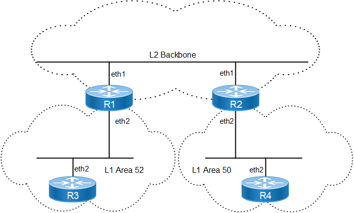
Single-Instance L1-L2 Area Routing
Configuration
R1
#configure terminal | Enter configure mode. |
|---|---|
(config-if)#commit | Commit candidate configuration to the running configuration |
(config)#interface eth1 | Enter interface mode. |
(config-if)#ip address 20.20.20.1/24 | Configure IP address on interface. |
(config-if)#ip router isis ABC | Enable IS-IS routing on the interface eth1 for area ABC. |
(config-if)#isis circuit-type level-2-only | Set the circuit type for the interface eth1. |
(config-if)#exit | Exit interface mode. |
(config)#interface eth2 | Enter interface mode. |
(config-if)#ip address 30.30.30.1/24 | Configure IP address on interface. |
(config-if)#ip router isis ABC | Enable IS-IS routing on the interface eth2 for area ABC. |
(config-if)#isis circuit-type level-1 | Set the circuit type for interface eth2 to level 1. |
(config-if)#commit | Commit candidate configuration to the running configuration |
(config-if)#exit | Exit interface mode. |
(config)#router isis ABC | Create an IS-IS routing instance for area ABC. |
(config-router)#net 52.0000.0000.0001.00 | Set a Network Entity Title for this instance, specifying the area address and the system ID. |
(config-router)#commit | Commit candidate configuration to the running configuration |
R2
(config)#interface eth1 | Enter interface mode. |
(config-if)#ip router isis bb | Enable IS-IS routing on the interface eth1 for area bb. |
(config-if)#ip address 20.20.20.2/24 | Configure IP address on interface. |
(config-if)#isis circuit-type level-2-only | Set the circuit type for the interface eth1 to level-2 only. |
(config-if)#commit | Commit candidate configuration to the running configuration |
(config-if)#exit | Exit interface mode. |
(config)#interface eth2 | Enter interface mode. |
(config-if)#ip address 40.40.40.1/24 | Configure IP address on interface. |
(config-if)#ip router isis bb | Enable IS-IS routing on interface eth2 for area bb. |
(config-if)#isis circuit-type level-1 | Set the circuit type for interface eth2 to level 1. |
(config-if)#commit | Commit candidate configuration to the running configuration |
(config-if)#exit | Exit interface mode. |
(config)#router isis bb | Create an IS-IS routing instance for area bb. |
(config-router)#net 50.0000.0000.0002.00 | Set a Network Entity Title for this instance, specifying the area address and the system ID. |
(config-if)#commit | Commit candidate configuration to the running configuration |
R3
(config)#interface eth2 | Enter interface mode. |
(config-if)#ip address 30.30.30.2/24 | Configure IP address on interface. |
(config-if)#ip router isis xyz | Enable IS-IS routing on the interface eth2 for area xyz. |
(config-if)#commit | Commit candidate configuration to the running configuration |
(config-if)#exit | Exit interface mode. |
(config)#router isis xyz | Create an IS-IS routing instance for area xyz. |
(config-router)#is-type level-1 | Set the IS level for this area (xyz) as level-1. |
(config-router)#net 52.0000.0000.0003.00 | Set a Network Entity Title for this instance, specifying the area address and the system ID. |
(config-if)#commit | Commit candidate configuration to the running configuration |
R4
(config)#interface eth2 | Enter interface mode. |
(config-if)#ip address 40.40.40.2/24 | Configure IP address on interface. |
(config-if)#ip router isis aa | Enable IS-IS routing on the interface eth2 for area aa. |
(config-if)#commit | Commit candidate configuration to the running configuration |
(config-if)#exit | Exit interface mode. |
(config)#router isis aa | Create an IS-IS routing instance for area aa. |
(config-router)#is-type level-1 | Set the IS level for this area (aa) as level-1. |
(config-router)#net 50.0000.0000.0004.00 | Set a Network Entity Title for this instance, specifying the area address and the system ID. |
(config-if)#commit | Commit candidate configuration to the running configuration |
Validation
R1#
R1#show clns neighbors
Total number of L1 adjacencies: 1
Total number of L2 adjacencies: 1
Total number of adjacencies: 2
Tag ABC: VRF : default
System Id Interface SNPA State Holdtime Type Protocol
0000.0000.0002 eth1 5254.002a.230a Up 20 L2 IS-IS
0000.0000.0003 eth2 5254.00a8.940d Up 6 L1 IS-IS
R2#show clns neighbors
Total number of L1 adjacencies: 1
Total number of L2 adjacencies: 1
Total number of adjacencies: 2
Tag bb: VRF : default
System Id Interface SNPA State Holdtime Type Protocol
0000.0000.0001 eth1 5254.00dc.0b76 Up 8 L2 IS-IS
0000.0000.0004 eth2 5254.00e2.aece Up 7 L1 IS-IS
R3#show clns neighbors
Total number of L1 adjacencies: 1
Total number of L2 adjacencies: 0
Total number of adjacencies: 1
Tag xyz: VRF : default
System Id Interface SNPA State Holdtime Type Protocol
0000.0000.0001 eth2 5254.00a1.6afe Up 23 L1 IS-IS
R4#show clns neighbors
Total number of L1 adjacencies: 1
Total number of L2 adjacencies: 0
Total number of adjacencies: 1
Tag aa: VRF : default
System Id Interface SNPA State Holdtime Type Protocol
0000.0000.0002 eth2 5254.007e.5ade Up 25 L1 IS-IS
R1#show ip isis route
Codes: C - connected, E - external, L1 - IS-IS level-1, L2 - IS-IS level-2
ia - IS-IS inter area, D - discard, e - external metric
** - invalid
Tag ABC: VRF : default
Destination Metric Next-Hop Interface Tag
C 20.20.20.0/24 10 -- eth1 0
C 30.30.30.0/24 10 -- eth2 0
L2 40.40.40.0/24 20 20.20.20.2 eth1 0
R2#show ip isis route
Codes: C - connected, E - external, L1 - IS-IS level-1, L2 - IS-IS level-2
ia - IS-IS inter area, D - discard, e - external metric
** - invalid
Tag bb: VRF : default
Destination Metric Next-Hop Interface Tag
C 20.20.20.0/24 10 -- eth1 0
L2 30.30.30.0/24 20 20.20.20.1 eth1 0
C 40.40.40.0/24 10 -- eth2 0
R3#show ip isis route
Codes: C - connected, E - external, L1 - IS-IS level-1, L2 - IS-IS level-2
ia - IS-IS inter area, D - discard, e - external metric
** - invalid
Tag xyz: VRF : default
Destination Metric Next-Hop Interface Tag
L1 0.0.0.0/0 10 30.30.30.1 eth2 0
C 30.30.30.0/24 10 -- eth2 0
R4#show ip isis route
Codes: C - connected, E - external, L1 - IS-IS level-1, L2 - IS-IS level-2
ia - IS-IS inter area, D - discard, e - external metric
** - invalid
Tag aa: VRF : default
Destination Metric Next-Hop Interface Tag
L1 0.0.0.0/0 10 40.40.40.1 eth2 0
C 40.40.40.0/24 10 -- eth2 0
R1#show isis topology
Tag ABC: VRF : default
IS-IS paths to level-1 routers
System Id Metric Next-Hop Interface SNPA
0000.0000.0001 --
0000.0000.0003 10 0000.0000.0003 eth2 5254.00a8.940d
IS-IS paths to level-2 routers
System Id Metric Next-Hop Interface SNPA
0000.0000.0001 --
0000.0000.0002 10 0000.0000.0002 eth1 5254.002a.230a
R2#show isis topology
Tag bb: VRF : default
IS-IS paths to level-1 routers
System Id Metric Next-Hop Interface SNPA
0000.0000.0002 --
0000.0000.0004 10 0000.0000.0004 eth2 5254.00e2.aece
IS-IS paths to level-2 routers
System Id Metric Next-Hop Interface SNPA
0000.0000.0001 10 0000.0000.0001 eth1 5254.00dc.0b76
0000.0000.0002 --
R3#show isis topology
Tag xyz: VRF : default
IS-IS paths to level-1 routers
System Id Metric Next-Hop Interface SNPA
0000.0000.0001 10 0000.0000.0001 eth2 5254.00a1.6afe
0000.0000.0003 --
R4#show isis topology
Tag aa: VRF : default
IS-IS paths to level-1 routers
System Id Metric Next-Hop Interface SNPA
0000.0000.0002 10 0000.0000.0002 eth2 5254.007e.5ade
0000.0000.0004 --
R1#show ip route
Codes: K - kernel, C - connected, S - static, R - RIP, B - BGP
O - OSPF, IA - OSPF inter area
N1 - OSPF NSSA external type 1, N2 - OSPF NSSA external type 2
E1 - OSPF external type 1, E2 - OSPF external type 2
i - IS-IS, L1 - IS-IS level-1, L2 - IS-IS level-2,
ia - IS-IS inter area, E - EVPN,
v - vrf leaked
* - candidate default
IP Route Table for VRF "default"
C 10.12.30.0/24 is directly connected, eth0, 00:27:08
C 20.20.20.0/24 is directly connected, eth1, 00:16:57
C 30.30.30.0/24 is directly connected, eth2, 00:15:48
i L2 40.40.40.0/24 [115/20] via 20.20.20.2, eth1, 00:15:05
C 127.0.0.0/8 is directly connected, lo, 00:27:08
Gateway of last resort is not set
R2#show ip route
Codes: K - kernel, C - connected, S - static, R - RIP, B - BGP
O - OSPF, IA - OSPF inter area
N1 - OSPF NSSA external type 1, N2 - OSPF NSSA external type 2
E1 - OSPF external type 1, E2 - OSPF external type 2
i - IS-IS, L1 - IS-IS level-1, L2 - IS-IS level-2,
ia - IS-IS inter area, E - EVPN,
v - vrf leaked
* - candidate default
IP Route Table for VRF "default"
C 10.12.30.0/24 is directly connected, eth0, 00:27:17
C 20.20.20.0/24 is directly connected, eth1, 00:17:13
i L2 30.30.30.0/24 [115/20] via 20.20.20.1, eth1, 00:16:18
C 40.40.40.0/24 is directly connected, eth2, 00:15:36
C 127.0.0.0/8 is directly connected, lo, 00:27:17
Gateway of last resort is not set
R3#show ip route
Codes: K - kernel, C - connected, S - static, R - RIP, B - BGP
O - OSPF, IA - OSPF inter area
N1 - OSPF NSSA external type 1, N2 - OSPF NSSA external type 2
E1 - OSPF external type 1, E2 - OSPF external type 2
i - IS-IS, L1 - IS-IS level-1, L2 - IS-IS level-2,
ia - IS-IS inter area, E - EVPN,
v - vrf leaked
* - candidate default
IP Route Table for VRF "default"
Gateway of last resort is 30.30.30.1 to network 0.0.0.0
i*L1 0.0.0.0/0 [115/10] via 30.30.30.1, eth2, 00:16:47
C 10.12.30.0/24 is directly connected, eth0, 00:27:46
C 30.30.30.0/24 is directly connected, eth2, 00:16:52
C 127.0.0.0/8 is directly connected, lo, 00:27:46
R4#show ip route
Codes: K - kernel, C - connected, S - static, R - RIP, B - BGP
O - OSPF, IA - OSPF inter area
N1 - OSPF NSSA external type 1, N2 - OSPF NSSA external type 2
E1 - OSPF external type 1, E2 - OSPF external type 2
i - IS-IS, L1 - IS-IS level-1, L2 - IS-IS level-2,
ia - IS-IS inter area, E - EVPN,
v - vrf leaked
* - candidate default
IP Route Table for VRF "default"
Gateway of last resort is 40.40.40.1 to network 0.0.0.0
i*L1 0.0.0.0/0 [115/10] via 40.40.40.1, eth2, 00:16:26
C 10.12.30.0/24 is directly connected, eth0, 00:27:20
C 40.40.40.0/24 is directly connected, eth2, 00:16:36
C 127.0.0.0/8 is directly connected, lo, 00:27:20
R1#show isis database
Tag ABC: VRF : default
IS-IS Level-1 Link State Database:
LSPID LSP Seq Num LSP Checksum LSP Holdtime ATT/P/OL
0000.0000.0001.00-00* 0x00000005 0xE66E 1165 1/0/0
0000.0000.0003.00-00 0x00000004 0xDC80 1164 0/0/0
0000.0000.0003.01-00 0x00000002 0x10C8 1163 0/0/0
IS-IS Level-2 Link State Database:
LSPID LSP Seq Num LSP Checksum LSP Holdtime ATT/P/OL
0000.0000.0001.00-00* 0x00000005 0xD0D8 1148 0/0/0
0000.0000.0001.01-00* 0x00000002 0x1FBA 1109 0/0/0
0000.0000.0002.00-00 0x00000005 0x7219 1189 0/0/0
R2#show isis database
Tag bb: VRF : default
IS-IS Level-1 Link State Database:
LSPID LSP Seq Num LSP Checksum LSP Holdtime ATT/P/OL
0000.0000.0002.00-00* 0x00000005 0x9583 1179 1/0/0
0000.0000.0004.00-00 0x00000004 0x8B95 1177 0/0/0
0000.0000.0004.01-00 0x00000002 0x2FA6 1177 0/0/0
IS-IS Level-2 Link State Database:
LSPID LSP Seq Num LSP Checksum LSP Holdtime ATT/P/OL
0000.0000.0001.00-00 0x00000005 0xD0D8 1116 0/0/0
0000.0000.0001.01-00 0x00000002 0x1FBA 1078 0/0/0
0000.0000.0002.00-00* 0x00000005 0x7219 1160 0/0/0
R3#show isis database
Tag xyz: VRF : default
IS-IS Level-1 Link State Database:
LSPID LSP Seq Num LSP Checksum LSP Holdtime ATT/P/OL
0000.0000.0001.00-00 0x00000005 0xE66E 1094 1/0/0
0000.0000.0003.00-00* 0x00000004 0xDC80 1095 0/0/0
0000.0000.0003.01-00* 0x00000002 0x10C8 1094 0/0/0
R4#show isis database
Tag aa: VRF : default
IS-IS Level-1 Link State Database:
LSPID LSP Seq Num LSP Checksum LSP Holdtime ATT/P/OL
0000.0000.0002.00-00 0x00000005 0x9583 1105 1/0/0
0000.0000.0004.00-00* 0x00000004 0x8B95 1105 0/0/0
0000.0000.0004.01-00* 0x00000002 0x2FA6 1105 0/0/0
L1-L2 Area Routing with Multiple Instances
IS-IS supports a two-level hierarchy for handling and scaling the functionality of large networks. The Level-1 (L1) area is mainly for Leaf networks, and the Level-2 (L2) area is the backbone area connecting Level-1 areas. In this example, R3 and R4 are configured as Level-1 routers, and reside in the Level-1 area. R1 and R2 are configured as Level-1-2 routers, and connect these two Level-1 areas with a backbone Level-2 area. You can configure Level-1-2 routers with single or multiple instances: This configuration shows the multiple-instance version of the Level-1-2 router.
Topology
Multiple-Instance L1-L2 Area Routing
Configuration
R1
#configure terminal | Enter configure mode. |
|---|---|
(config)#interface eth1 | Enter interface mode. |
(config-if)#ip address 20.20.20.1/24 | Configure IP address on interface. |
(config-if)#ip router isis aaa | Enable IS-IS routing on interface eth1 for area aaa. |
(config-if)#commit | Commit candidate configuration to the running configuration |
(config-if)#exit | Exit interface mode. |
(config)#router isis aaa | Create an IS-IS routing instance for area aaa. |
(config-router)#is-type level-2-only | Set the IS level for this area (aaa) as level-2-only. |
(config-router)#net bb.0000.0000.0001.00 | Set a Network Entity Title for this instance, specifying the area address and the system ID. |
(config-if)#commit | Commit candidate configuration to the running configuration |
(config-router)#exit | Exit Router mode, and return to Configure mode. |
(config)#interface eth2 | Enter interface mode. |
(config-if)#ip address 30.30.30.1/24 | Configure IP address on interface. |
(config-if)#ip router isis ccc | Enable IS-IS routing on interface eth2 for area ccc. |
(config-if)#commit | Commit candidate configuration to the running configuration |
(config-if)#exit | Exit interface mode. |
(config)#router isis ccc | Create an IS-IS routing instance for area ccc. |
(config-router)#is-type level-1 | Set the IS level for this area (ccc) as level-1. |
(config-router)#net cc.0000.0000.0002.00 | Set a Network Entity Title for this instance, specifying the area address and the system ID. |
(config-if)#commit | Commit candidate configuration to the running configuration |
R2
(config)#interface eth1 | Enter interface mode. |
(config-if)#ip address 20.20.20.2/24 | Configure IP address on interface. |
(config-if)#ip router isis bb | Enable IS-IS routing on interface eth1 for area bb. |
(config-if)#commit | Commit candidate configuration to the running configuration |
(config-if)#exit | Exit interface mode. |
(config)#router isis bb | Create an IS-IS routing instance for area bb. |
(config-router)#is-type level-2-only | Set the IS level for this area (bb) as level-2-only. |
(config-router)#net bb.0000.0000.0002.00 | Set a Network Entity Title for this instance, specifying the area address and the system ID. |
(config-if)#commit | Commit candidate configuration to the running configuration |
(config-router)#exit | Exit Router mode, and return to Configure mode. |
(config)#interface eth2 | Enter interface mode. |
(config-if)#ip address 40.40.40.1/24 | Configure IP address on interface. |
(config-if)#ip router isis ABC | Enable IS-IS routing on interface eth2 for area ABC. |
(config-if)#commit | Commit candidate configuration to the running configuration |
(config-if)#exit | Exit interface mode. |
(config)#router isis ABC | Create an IS-IS routing instance for area ABC. |
(config-router)#is-type level-1 | Set the IS level for this area (ABC) as level-1. |
(config-router)#net cc.0000.0000.0003.00 | Set a Network Entity Title for this instance, specifying the area address and the system ID. |
(config-if)#commit | Commit candidate configuration to the running configuration |
R3
(config)#interface eth2 | Enter interface mode. |
(config-if)#ip address 30.30.30.2/24 | Configure IP address on interface. |
(config-if)#ip router isis xyz | Enable IS-IS routing on interface eth2 for area xyz. |
(config-if)#exit | Exit interface mode. |
(config)#router isis xyz | Create an IS-IS routing instance for area xyz. |
(config-router)#is-type level-1 | Set the IS level for this area (xyz) as level-1. |
(config-router)#net 52.0000.0000.0003.00 | Set a Network Entity Title for this instance, specifying the area address and the system ID. |
R4
(config)#interface eth2 | Enter interface mode. |
(config-if)#ip address 40.40.40.2/24 | Configure IP address on interface. |
(config-if)#ip router isis aa | Enable IS-IS routing on interface eth2 for area aa. |
(config-if)#exit | Exit interface mode. |
(config)#router isis aa | Create an IS-IS routing instance for area aa. |
(config-router)#is-type level-1 | Set the IS level for this area (aa) as level-1. |
(config-router)#net 52.0000.0000.0004.00 | Set a Network Entity Title for this instance, specifying the area address and the system ID. |
Validation
R1#show clns neighbors
Total number of L1 adjacencies: 0
Total number of L2 adjacencies: 1
Total number of adjacencies: 1
Tag aaa: VRF : default
System Id Interface SNPA State Holdtime Type Protocol
0000.0000.0002 eth1 5254.002a.230a Up 25 L2 IS-IS
Total number of L1 adjacencies: 0
Total number of L2 adjacencies: 0
Total number of adjacencies: 0
Tag ccc: VRF : default
System Id Interface SNPA State Holdtime Type Protocol
R2#show clns neighbors
Total number of L1 adjacencies: 0
Total number of L2 adjacencies: 0
Total number of adjacencies: 0
Tag ABC: VRF : default
System Id Interface SNPA State Holdtime Type Protocol
Total number of L1 adjacencies: 0
Total number of L2 adjacencies: 1
Total number of adjacencies: 1
Tag bb: VRF : default
System Id Interface SNPA State Holdtime Type Protocol
0000.0000.0001 eth1 5254.00dc.0b76 Up 6 L2 IS-IS
R1#show clns is-neighbors
Tag aaa: VRF : default
System Id Interface State Type Priority Circuit Id
0000.0000.0002 eth1 Up L2 64 0000.0000.0001.01
Tag ccc: VRF : default
System Id Interface State Type Priority Circuit Id
R2#show clns is-neighbors
Tag ABC: VRF : default
System Id Interface State Type Priority Circuit Id
Tag bb: VRF : default
System Id Interface State Type Priority Circuit Id
0000.0000.0001 eth1 Up L2 64 0000.0000.0001.01
R1#show ip isis route
Codes: C - connected, E - external, L1 - IS-IS level-1, L2 - IS-IS level-2
ia - IS-IS inter area, D - discard, e - external metric
** - invalid
Tag aaa: VRF : default
Destination Metric Next-Hop Interface Tag
C 20.20.20.0/24 10 -- eth1 0
Codes: C - connected, E - external, L1 - IS-IS level-1, L2 - IS-IS level-2
ia - IS-IS inter area, D - discard, e - external metric
** - invalid
Tag ccc: VRF : default
Destination Metric Next-Hop Interface Tag
C 30.30.30.0/24 10 -- eth2 0
R2#show ip isis route
Codes: C - connected, E - external, L1 - IS-IS level-1, L2 - IS-IS level-2
ia - IS-IS inter area, D - discard, e - external metric
** - invalid
Tag ABC: VRF : default
Destination Metric Next-Hop Interface Tag
C 40.40.40.0/24 10 -- eth2 0
Codes: C - connected, E - external, L1 - IS-IS level-1, L2 - IS-IS level-2
ia - IS-IS inter area, D - discard, e - external metric
** - invalid
Tag bb: VRF : default
Destination Metric Next-Hop Interface Tag
C 20.20.20.0/24 10 -- eth1 0
R1#show isis topology
Tag aaa: VRF : default
IS-IS paths to level-2 routers
System Id Metric Next-Hop Interface SNPA
0000.0000.0001 --
0000.0000.0002 10 0000.0000.0002 eth1 5254.002a.230a
Tag ccc: VRF : default
IS-IS paths to level-1 routers
System Id Metric Next-Hop Interface SNPA
0000.0000.0002 --
R2#show isis topology
Tag ABC: VRF : default
IS-IS paths to level-1 routers
System Id Metric Next-Hop Interface SNPA
0000.0000.0003 --
Tag bb: VRF : default
IS-IS paths to level-2 routers
System Id Metric Next-Hop Interface SNPA
0000.0000.0001 10 0000.0000.0001 eth1 5254.00dc.0b76
0000.0000.0002 --
R1#show isis database
Tag aaa: VRF : default
IS-IS Level-2 Link State Database:
LSPID LSP Seq Num LSP Checksum LSP Holdtime ATT/P/OL
0000.0000.0001.00-00* 0x00000002 0x181D 1003 0/0/0
0000.0000.0001.01-00* 0x00000001 0x21B9 1003 0/0/0
0000.0000.0002.00-00 0x00000005 0x1818 1080 0/0/0
Tag ccc: VRF : default
IS-IS Level-1 Link State Database:
LSPID LSP Seq Num LSP Checksum LSP Holdtime ATT/P/OL
0000.0000.0002.00-00* 0x00000001 0xDFA5 685 0/0/0
R2#show isis database
Tag ABC: VRF : default
IS-IS Level-1 Link State Database:
LSPID LSP Seq Num LSP Checksum LSP Holdtime ATT/P/OL
0000.0000.0003.00-00* 0x00000002 0xD571 696 0/0/0
Tag bb: VRF : default
IS-IS Level-2 Link State Database:
LSPID LSP Seq Num LSP Checksum LSP Holdtime ATT/P/OL
0000.0000.0001.00-00 0x00000002 0x181D 938 0/0/0
0000.0000.0001.01-00 0x00000001 0x21B9 938 0/0/0
0000.0000.0002.00-00* 0x00000005 0x1818 1017 0/0/0
R1#show ip route
Codes: K - kernel, C - connected, S - static, R - RIP, B - BGP
O - OSPF, IA - OSPF inter area
N1 - OSPF NSSA external type 1, N2 - OSPF NSSA external type 2
E1 - OSPF external type 1, E2 - OSPF external type 2
i - IS-IS, L1 - IS-IS level-1, L2 - IS-IS level-2,
ia - IS-IS inter area, E - EVPN,
v - vrf leaked
* - candidate default
IP Route Table for VRF "default"
C 10.12.30.0/24 is directly connected, eth0, 01:37:50
C 20.20.20.0/24 is directly connected, eth1, 00:10:13
C 30.30.30.0/24 is directly connected, eth2, 00:10:13
C 127.0.0.0/8 is directly connected, lo, 01:37:50
Gateway of last resort is not set
R2#show ip route
Codes: K - kernel, C - connected, S - static, R - RIP, B - BGP
O - OSPF, IA - OSPF inter area
N1 - OSPF NSSA external type 1, N2 - OSPF NSSA external type 2
E1 - OSPF external type 1, E2 - OSPF external type 2
i - IS-IS, L1 - IS-IS level-1, L2 - IS-IS level-2,
ia - IS-IS inter area, E - EVPN,
v - vrf leaked
* - candidate default
IP Route Table for VRF "default"
C 10.12.30.0/24 is directly connected, eth0, 01:37:26
C 20.20.20.0/24 is directly connected, eth1, 00:05:03
C 40.40.40.0/24 is directly connected, eth2, 00:08:52
C 127.0.0.0/8 is directly connected, lo, 01:37:26
Gateway of last resort is not set
Route Leaking
Route leaking is defined in RFC 2966. For Level-1 (L1) routers, only level-1 routes are populated in the routing table. The L1 router has a default route to the nearest Level-1/Level-2 (L1/L2) router: This could result in sub-optimal routing in certain scenarios. Route leaking causes an L1/L2 router to advertise the level-2 routes in its database to the L1 router, thus allowing the L1 router to acknowledge the prefixes advertised by the Level-2 (L2) router. In this way, the L1 router has the ability to learn the true cost to reach other areas.
In the following example, R1 is the L1 router, R2 is the L1/L2 router doing the route leaking, and R3 is the L2 router. The following configuration is given only for R2, assuming that the adjacency with R1 and R3 are already up, and the route tables with appropriate routes are already populated.
Topology
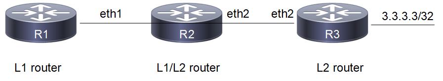
Route Leaking Topology
Configuration
R1
#configure terminal | Enter configure mode. |
(config)#router isis 1 | Create an IS-IS routing instance (1). |
(config-router)#net 49.0001.0000.0000.0001.00 | Define the NET address. |
(config-router)#is-type level-1 | Configure instance as level-1. |
(config-if)#commit | Commit candidate configuration to the running configuration |
(config-router)#exit | Exit router mode. |
(config)#interface eth1 | Specify the interface (eth1)to configure and enter Interface mode. |
(config-if)#ip address 20.20.20.1/24 | Configure IP address on interface. |
(config-if)#isis circuit-type level-1 | Set the circuit type as level-1 for the interface |
(config-if)#ip router isis 1 | Enable IS-IS routing on interface eth1 (connected to R2). |
(config-if)#commit | Commit candidate configuration to the running configuration |
R2
#configure terminal | Enter configure mode. |
(config)#interface eth1 | Specify the interface (eth1)to configure and enter Interface mode. |
(config-if)#ip address 20.20.20.2/24 | Configure IP address on interface. |
(config-if)#ip router isis 1 | Enable IS-IS routing on interface eth1 (connected to R1). |
(config-if)#isis circuit-type level-1 | Configure instance as level-1-only routing. |
(config-if)#commit | Commit candidate configuration to the running configuration |
(config-if)#exit | Exit interface mode and return to Configure mode. |
(config)#interface eth2 | Specify the interface (eth2)to configure and enter Interface mode. |
(config-if)#ip address 30.30.30.1/24 | Configure IP address on interface. |
(config-if)#ip router isis 1 | Enable IS-IS routing on interface eth2 (connected to R3). |
(config-if)#isis circuit-type level-2-only | Configure instance as level-2-only routing. |
(config-if)#commit | Commit candidate configuration to the running configuration |
(config-if)#exit | Exit interface mode and return to Configure mode. |
(config)#router isis 1 | Create an IS-IS routing instance (1). |
(config-router)#net 49.0001.0000.0000.0002.00 | Define the NET address. |
(config-router-af)#redistribute isis level-2 into level-1 | Enable redistribution of isis routes from level-2 into level-1 |
(config-if)#commit | Commit candidate configuration to the running configuration |
R3
#configure terminal | Enter configure mode. |
(config)#interface lo | Specify the interface (lo)to configure and enter Interface mode. |
(config-if)#ip address 3.3.3.3/32 secondary | Configure IP address on loopback interface. |
(config-if)#ip router isis 1 | Enable IS-IS routing on interface lo |
(config-if)#commit | Commit candidate configuration to the running configuration |
(config-if)#exit | Exit interface mode and return to Configure mode. |
(config)#router isis 1 | Create an IS-IS routing instance (1). |
(config-router)#is-type level-2-only | Configure instance as level-2-only routing. |
(config-router)#net 49.0001.0000.0000.0003.00 | Define the NET address. |
(config-if)#commit | Commit candidate configuration to the running configuration |
(config-router)#exit | Exit router mode. |
(config)#interface eth2 | Specify the interface (eth2)to configure and enter Interface mode. |
(config-if)#ip address 30.30.30.2/24 | Configure IP address on interface. |
(config-if)#isis circuit-type level-2-only | Set the circuit type as level-2-only for the interface |
(config-if)#ip router isis 1 | Enable IS-IS routing on interface eth1 (connected to R2). |
(config-if)#commit | Commit candidate configuration to the running configuration |
In the example, route, i ia 3.3.3.3/32 [115/30] via 20.20.20.2, eth1, 00:12:29, is the L2 route leaked by the L1/L2 router into the L1 router.
Validation
R1#show clns neighbors
Total number of L1 adjacencies: 1
Total number of L2 adjacencies: 0
Total number of adjacencies: 1
Tag 1: VRF : default
System Id Interface SNPA State Holdtime Type Protocol
0000.0000.0002 eth1 5254.002a.230a Up 21 L1 IS-IS
R2#show clns neighbors
Total number of L1 adjacencies: 1
Total number of L2 adjacencies: 1
Total number of adjacencies: 2
Tag 1: VRF : default
System Id Interface SNPA State Holdtime Type Protocol
0000.0000.0001 eth1 5254.00dc.0b76 Up 5 L1 IS-IS
0000.0000.0003 eth2 5254.00a8.940d Up 6 L2 IS-IS
R3#show clns neighbors
Total number of L1 adjacencies: 0
Total number of L2 adjacencies: 1
Total number of adjacencies: 1
Tag 1: VRF : default
System Id Interface SNPA State Holdtime Type Protocol
0000.0000.0002 eth2 5254.007e.5ade Up 21 L2 IS-IS
R1#show ip isis route
Codes: C - connected, E - external, L1 - IS-IS level-1, L2 - IS-IS level-2
ia - IS-IS inter area, D - discard, e - external metric
** - invalid
Tag 1: VRF : default
Destination Metric Next-Hop Interface Tag
ia 3.3.3.3/32 30 20.20.20.2 eth1 0
C 20.20.20.0/24 10 -- eth1 0
ia 30.30.30.0/24 20 20.20.20.2 eth1 0
R2#show ip isis route
Codes: C - connected, E - external, L1 - IS-IS level-1, L2 - IS-IS level-2
ia - IS-IS inter area, D - discard, e - external metric
** - invalid
Tag 1: VRF : default
Destination Metric Next-Hop Interface Tag
L2 3.3.3.3/32 20 30.30.30.2 eth2 0
C 20.20.20.0/24 10 -- eth1 0
C 30.30.30.0/24 10 -- eth2 0
R3#show ip isis route
Codes: C - connected, E - external, L1 - IS-IS level-1, L2 - IS-IS level-2
ia - IS-IS inter area, D - discard, e - external metric
** - invalid
Tag 1: VRF : default
Destination Metric Next-Hop Interface Tag
C 3.3.3.3/32 10 -- lo 0
L2 20.20.20.0/24 20 30.30.30.1 eth2 0
C 30.30.30.0/24 10 -- eth2 0
R1#show ip route
Codes: K - kernel, C - connected, S - static, R - RIP, B - BGP
O - OSPF, IA - OSPF inter area
N1 - OSPF NSSA external type 1, N2 - OSPF NSSA external type 2
E1 - OSPF external type 1, E2 - OSPF external type 2
i - IS-IS, L1 - IS-IS level-1, L2 - IS-IS level-2,
ia - IS-IS inter area, E - EVPN,
v - vrf leaked
* - candidate default
IP Route Table for VRF "default"
i ia 3.3.3.3/32 [115/30] via 20.20.20.2, eth1, 00:20:53
C 10.12.30.0/24 is directly connected, eth0, 01:02:10
C 20.20.20.0/24 is directly connected, eth1, 00:48:08
i ia 30.30.30.0/24 [115/20] via 20.20.20.2, eth1, 00:23:30
C 127.0.0.0/8 is directly connected, lo, 01:02:10
Gateway of last resort is not set
R2#show ip route
Codes: K - kernel, C - connected, S - static, R - RIP, B - BGP
O - OSPF, IA - OSPF inter area
N1 - OSPF NSSA external type 1, N2 - OSPF NSSA external type 2
E1 - OSPF external type 1, E2 - OSPF external type 2
i - IS-IS, L1 - IS-IS level-1, L2 - IS-IS level-2,
ia - IS-IS inter area, E - EVPN,
v - vrf leaked
* - candidate default
IP Route Table for VRF "default"
i L2 3.3.3.3/32 [115/20] via 30.30.30.2, eth2, 00:21:07
C 10.12.30.0/24 is directly connected, eth0, 01:01:55
C 20.20.20.0/24 is directly connected, eth1, 00:48:12
C 30.30.30.0/24 is directly connected, eth2, 00:48:12
C 127.0.0.0/8 is directly connected, lo, 01:01:55
Gateway of last resort is not set
R3#show ip route
Codes: K - kernel, C - connected, S - static, R - RIP, B - BGP
O - OSPF, IA - OSPF inter area
N1 - OSPF NSSA external type 1, N2 - OSPF NSSA external type 2
E1 - OSPF external type 1, E2 - OSPF external type 2
i - IS-IS, L1 - IS-IS level-1, L2 - IS-IS level-2,
ia - IS-IS inter area, E - EVPN,
v - vrf leaked
* - candidate default
IP Route Table for VRF "default"
C 3.3.3.3/32 is directly connected, lo, 00:21:25
C 10.12.30.0/24 is directly connected, eth0, 01:01:26
i L2 20.20.20.0/24 [115/20] via 30.30.30.1, eth2, 00:24:06
C 30.30.30.0/24 is directly connected, eth2, 00:48:13
C 127.0.0.0/8 is directly connected, lo, 01:01:26
Gateway of last resort is not set
R1#show isis database
Tag 1: VRF : default
IS-IS Level-1 Link State Database:
LSPID LSP Seq Num LSP Checksum LSP Holdtime ATT/P/OL
0000.0000.0001.00-00* 0x0000000C 0xE4B5 642 0/0/0
0000.0000.0001.01-00* 0x00000007 0x13C3 642 0/0/0
0000.0000.0002.00-00 0x00000012 0x8AC8 804 0/0/0
R2#show isis database
Tag 1: VRF : default
IS-IS Level-1 Link State Database:
LSPID LSP Seq Num LSP Checksum LSP Holdtime ATT/P/OL
0000.0000.0001.00-00 0x00000003 0xF6AC 304 0/0/0
0000.0000.0001.01-00 0x00000002 0x1DBE 304 0/0/0
0000.0000.0002.00-00* 0x00000009 0x2ECA 358 0/0/0
IS-IS Level-2 Link State Database:
LSPID LSP Seq Num LSP Checksum LSP Holdtime ATT/P/OL
0000.0000.0002.00-00* 0x00000007 0x2F5A 353 0/0/0
0000.0000.0003.00-00 0x00000003 0x25E6 347 0/0/0
0000.0000.0003.02-00 0x00000002 0x24B0 347 0/0/0
R3#show isis database
Tag 1: VRF : default
IS-IS Level-2 Link State Database:
LSPID LSP Seq Num LSP Checksum LSP Holdtime ATT/P/OL
0000.0000.0002.00-00 0x00000007 0x2F5A 335 0/0/0
0000.0000.0003.00-00* 0x00000003 0x25E6 331 0/0/0
0000.0000.0003.02-00* 0x00000002 0x24B0 331 0/0/0
R1#show isis topology
Tag 1: VRF : default
IS-IS paths to level-1 routers
System Id Metric Next-Hop Interface SNPA
0000.0000.0001 --
0000.0000.0002 10 0000.0000.0002 eth1 5254.002a.230a
R2#show isis topology
Tag 1: VRF : default
IS-IS paths to level-1 routers
System Id Metric Next-Hop Interface SNPA
0000.0000.0001 10 0000.0000.0001 eth1 5254.00dc.0b76
0000.0000.0002 --
IS-IS paths to level-2 routers
System Id Metric Next-Hop Interface SNPA
0000.0000.0002 --
0000.0000.0003 10 0000.0000.0003 eth2 5254.00a8.940d
R3#show isis topology
Tag 1: VRF : default
IS-IS paths to level-2 routers
System Id Metric Next-Hop Interface SNPA
0000.0000.0002 10 0000.0000.0002 eth2 5254.007e.5ade
0000.0000.0003 --
Route Summarization
Route summarization makes the routing table smaller, but still allows complete IP connectivity, if everything is configured properly.
The following example consists of a three-router topology, in which R2 is doing the summarization. In this example, R1 is the L1 router, R2 is the L1/L2 router doing the summarization, and R3 is the L2 router. The following configuration is given only for R2, assuming that the adjacencies with R1 and R3 are already up, and the route tables with the appropriate routes are already populated.
Topology

Route Summarization Topology
Configuration
R1
#configure terminal | Enter configure mode. |
(config)#router isis 1 | Create an IS-IS routing instance (1). |
(config-router)#net 49.0001.0000.0000.0001.00 | Define the NET address. |
(config-router)#is-type level-1 | Configure instance as level-1. |
(config-if)#commit | Commit candidate configuration to the running configuration |
(config-router)#exit | Exit router mode. |
(config)#interface eth1 | Specify the interface (eth1)to configure and enter Interface mode. |
(config-if)#ip address 20.20.20.1/24 | Configure IP address on interface. |
(config-if)#isis circuit-type level-1 | Set the circuit type as level-1 for the interface |
(config-if)#ip router isis 1 | Enable IS-IS routing on interface eth1 (connected to R2). |
(config-if)#commit | Commit candidate configuration to the running configuration |
R2
#configure terminal | Enter configure mode. |
(config)#interface eth1 | Specify the interface (eth1)to configure and enter Interface mode. |
(config-if)#isis circuit-type level-1 | Set the circuit type as level-1 for the interface |
(config-if)#ip address 20.20.20.2/24 | Configure IP address on interface. |
(config-if)#ip router isis 1 | Enable IS-IS routing on interface eth1 (connected to R1). |
(config-if)#commit | Commit candidate configuration to the running configuration |
(config-if)#exit | Exit interface mode and return to Configure mode. |
(config)#interface eth2 | Specify the interface (eth2)to configure and enter Interface mode. |
(config-if)#ip address 30.30.30.1/24 | Configure IP address on interface. |
(config-if)#isis circuit-type level-2-only | Set the circuit type as level-2-only for the interface |
(config-if)#ip router isis 1 | Enable IS-IS routing on interface eth2 (connected to R3). |
(config-if)#commit | Commit candidate configuration to the running configuration |
(config-if)#exit | Exit interface mode and return to Configure mode. |
(config)#router isis 1 | Create an IS-IS routing instance (1). |
(config-router)#net 49.0001.0000.0000.0002.00 | Define the NET address. |
(config-router-af)#redistribute isis level-2 into level-1 | Enable redistribution of isis routes from level-2 into level-1 |
(config-router-af)#summary-address 66.66.66.0/24 level-1 metric 50 | Configure the summary address to summarize IP reachability information. |
(config-if)#commit | Commit candidate configuration to the running configuration |
R3
#configure terminal | Enter configure mode. |
(config)#ip route 66.66.66.1/32 eth2 | Configure ip static route. |
(config)#ip route 66.66.66.2/32 eth2 | Configure ip static route. |
(config)#ip route 66.66.66.3/32 eth2 | Configure ip static route. |
(config)#router isis 1 | Create an IS-IS routing instance (1). |
(config-router)#is-type level-2-only | Configure instance as level-2-only routing. |
(config-router)#net 49.0001.0000.0000.0003.00 | Define the NET address. |
(config-router)#redistribute static | Enable redistribution of static routes into ISIS instance. |
(config-if)#commit | Commit candidate configuration to the running configuration |
(config-router)#exit | Exit router mode. |
(config)#interface eth2 | Specify the interface (eth2)to configure and enter Interface mode. |
(config-if)#ip address 30.30.30.2/24 | Configure IP address on interface. |
(config-if)#isis circuit-type level-2-only | Set the circuit type as level-2-only for the interface |
(config-if)#ip router isis 1 | Enable IS-IS routing on interface eth1 (connected to R2). |
(config-if)#commit | Commit candidate configuration to the running configuration |
Validation
R1#show clns neighbors
Total number of L1 adjacencies: 1
Total number of L2 adjacencies: 0
Total number of adjacencies: 1
Tag 1: VRF : default
System Id Interface SNPA State Holdtime Type Protocol
0000.0000.0002 eth1 5254.002a.230a Up 20 L1 IS-IS
R2#show clns neighbors
Total number of L1 adjacencies: 1
Total number of L2 adjacencies: 1
Total number of adjacencies: 2
Tag 1: VRF : default
System Id Interface SNPA State Holdtime Type Protocol
0000.0000.0001 eth1 5254.00dc.0b76 Up 6 L1 IS-IS
0000.0000.0003 eth2 5254.00a8.940d Up 7 L2 IS-IS
R3#show clns neighbors
Total number of L1 adjacencies: 0
Total number of L2 adjacencies: 1
Total number of adjacencies: 1
Tag 1: VRF : default
System Id Interface SNPA State Holdtime Type Protocol
0000.0000.0002 eth2 5254.007e.5ade Up 21 L2 IS-IS
R1#show ip isis route
Codes: C - connected, E - external, L1 - IS-IS level-1, L2 - IS-IS level-2
ia - IS-IS inter area, D - discard, e - external metric
** - invalid
Tag 1: VRF : default
Destination Metric Next-Hop Interface Tag
C 20.20.20.0/24 10 -- eth1 0
ia 30.30.30.0/24 20 20.20.20.2 eth1 0
ia 66.66.66.0/24 60 20.20.20.2 eth1 0
R2#show ip isis route
Codes: C - connected, E - external, L1 - IS-IS level-1, L2 - IS-IS level-2
ia - IS-IS inter area, D - discard, e - external metric
** - invalid
Tag 1: VRF : default
Destination Metric Next-Hop Interface Tag
C 20.20.20.0/24 10 -- eth1 0
C 30.30.30.0/24 10 -- eth2 0
D 66.66.66.0/24 0 -- --
L2 66.66.66.1/32 10 30.30.30.2 eth2 0
L2 66.66.66.2/32 10 30.30.30.2 eth2 0
L2 66.66.66.3/32 10 30.30.30.2 eth2 0
R3#show ip isis route
Codes: C - connected, E - external, L1 - IS-IS level-1, L2 - IS-IS level-2
ia - IS-IS inter area, D - discard, e - external metric
** - invalid
Tag 1: VRF : default
Destination Metric Next-Hop Interface Tag
L2 20.20.20.0/24 20 30.30.30.1 eth2 0
C 30.30.30.0/24 10 -- eth2 0
E 66.66.66.1/32 0 -- -- 0
E 66.66.66.2/32 0 -- -- 0
E 66.66.66.3/32 0 -- -- 0
R1#show isis database verbose
Tag 1: VRF : default
IS-IS Level-1 Link State Database:
LSPID LSP Seq Num LSP Checksum LSP Holdtime ATT/P/OL
0000.0000.0001.00-00* 0x00000004 0xF4AD 850 0/0/0
Area Address: 49.0001
NLPID: 0xCC
IP Address: 20.20.20.1
Metric: 10 IS 0000.0000.0001.01
Metric: 10 IP 20.20.20.0 255.255.255.0
0000.0000.0001.01-00* 0x00000003 0x1BBF 850 0/0/0
Metric: 0 IS 0000.0000.0001.00
Metric: 0 IS 0000.0000.0002.00
0000.0000.0002.00-00 0x00000010 0xB5E0 1165 0/0/0
Area Address: 49.0001
NLPID: 0xCC
IP Address: 20.20.20.2
Metric: 10 IS 0000.0000.0001.01
Metric: 10 IP 20.20.20.0 255.255.255.0
Metric: 10 IP-Interarea 30.30.30.0 255.255.255.0
Metric: 50 IP-External 66.66.66.0 255.255.255.0
R2#show isis database verbose
Tag 1: VRF : default
IS-IS Level-1 Link State Database:
LSPID LSP Seq Num LSP Checksum LSP Holdtime ATT/P/OL
0000.0000.0001.00-00 0x00000004 0xF4AD 820 0/0/0
Area Address: 49.0001
NLPID: 0xCC
IP Address: 20.20.20.1
Metric: 10 IS 0000.0000.0001.01
Metric: 10 IP 20.20.20.0 255.255.255.0
0000.0000.0001.01-00 0x00000003 0x1BBF 820 0/0/0
Metric: 0 IS 0000.0000.0001.00
Metric: 0 IS 0000.0000.0002.00
0000.0000.0002.00-00* 0x00000010 0xB5E0 1137 0/0/0
Area Address: 49.0001
NLPID: 0xCC
IP Address: 20.20.20.2
Metric: 10 IS 0000.0000.0001.01
Metric: 10 IP 20.20.20.0 255.255.255.0
Metric: 10 IP-Interarea 30.30.30.0 255.255.255.0
Metric: 50 IP-External 66.66.66.0 255.255.255.0
IS-IS Level-2 Link State Database:
LSPID LSP Seq Num LSP Checksum LSP Holdtime ATT/P/OL
0000.0000.0002.00-00* 0x00000005 0x1577 838 0/0/0
Area Address: 49.0001
NLPID: 0xCC
IP Address: 30.30.30.1
Metric: 10 IS 0000.0000.0003.01
Metric: 10 IP 30.30.30.0 255.255.255.0
Metric: 10 IP 20.20.20.0 255.255.255.0
0000.0000.0003.00-00 0x0000000B 0xFED3 1160 0/0/0
Area Address: 49.0001
NLPID: 0xCC
IP Address: 30.30.30.2
Metric: 10 IS 0000.0000.0003.01
Metric: 10 IP 30.30.30.0 255.255.255.0
Metric: 0 IP-External 66.66.66.1 255.255.255.255
Metric: 0 IP-External 66.66.66.2 255.255.255.255
Metric: 0 IP-External 66.66.66.3 255.255.255.255
0000.0000.0003.01-00 0x00000003 0x29AB 837 0/0/0
Metric: 0 IS 0000.0000.0003.00
Metric: 0 IS 0000.0000.0002.00
R3#show isis database verbose
Tag 1: VRF : default
IS-IS Level-2 Link State Database:
LSPID LSP Seq Num LSP Checksum LSP Holdtime ATT/P/OL
0000.0000.0002.00-00 0x00000005 0x1577 818 0/0/0
Area Address: 49.0001
NLPID: 0xCC
IP Address: 30.30.30.1
Metric: 10 IS 0000.0000.0003.01
Metric: 10 IP 30.30.30.0 255.255.255.0
Metric: 10 IP 20.20.20.0 255.255.255.0
0000.0000.0003.00-00* 0x0000000B 0xFED3 1142 0/0/0
Area Address: 49.0001
NLPID: 0xCC
IP Address: 30.30.30.2
Metric: 10 IS 0000.0000.0003.01
Metric: 10 IP 30.30.30.0 255.255.255.0
Metric: 0 IP-External 66.66.66.1 255.255.255.255
Metric: 0 IP-External 66.66.66.2 255.255.255.255
Metric: 0 IP-External 66.66.66.3 255.255.255.255
0000.0000.0003.01-00* 0x00000003 0x29AB 819 0/0/0
Metric: 0 IS 0000.0000.0003.00
Metric: 0 IS 0000.0000.0002.00
IS-IS Distance
Administrative distance in IS-IS can be configured for a specified source ID or for all routes.
This example shows configuring the IS-IS administrative distance for the IPv4 address family.
Topology
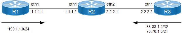
IS-IS Distance Topology
Configuration
R1
#configure terminal | Enter configure mode. |
(config)#interface eth1 | Enter interface mode. |
(config-if)#ip address 1.1.1.1/24 | Assign the IP address on this interface (eth1). |
(config-if)#ip router isis 1 | Enable IS-IS routing on interface eth1. |
(config-if)#commit | Commit candidate configuration to the running configuration |
(config-if)#exit | |
(config)#ip route 150.1.1.0/24 eth1 | Configure static routes. |
(config)#router isis 1 | Create an IS-IS routing instance (1). |
(config-router)#net 49.0001.0000.0001.00 | Set a Network Entity Title (NET) for this instance, specifying the address and the system ID. |
(config-router)#redistribute static | Redistribute the static routes. |
(config-if)#commit | Commit candidate configuration to the running configuration |
R2
#configure terminal | Enter configure mode |
(config)#ip access-list DIST | Enter access list mode |
(config-ip-acl)#permit ipip 88.88.1.2/32 any | Create an access list to permit the 88.88.1.2/32 route from R3. |
(config-if)#commit | Commit candidate configuration to the running configuration |
(config-ip-acl)#exit | Exit access list mode |
(config)#interface eth1 | Enter interface mode. |
(config-if)#ip address 1.1.1.2/24 | Assign the IP address on this interface (eth1). |
(config-if)#ip router isis 1 | Enable IS-IS routing on interface eth1 |
(config-if)#commit | Commit candidate configuration to the running configuration |
(config-if)#exit | Exit interface mode |
(config)#interface eth2 | Enter interface mode. |
(config-if)#ip address 2.2.2.1/24 | Assign the IP address on this interface (eth2). |
(config-if)#ip router isis 1 | Enable IS-IS routing on interface eth2 |
(config-if)#commit | Commit candidate configuration to the running configuration |
(config-if)#exit | Exit interface mode |
(config)#router isis 1 | Create an IS-IS routing instance (1). |
(config-router)#net 49.0001.0000.0002.00 | Specify the NET address. |
(config-router)#distance 100 | Configure the administrative distance for all routes received from R1 and R2. |
(config-router)#distance 20 0001.0000.0001 | Configure the administrative distance for all routes received from R1. This command overwrites the applied distance, 100, and will apply distance 20 for all routes received from R1. |
(config-router)#distance 30 0001.0000.0003 DIST | Configure the distance, 30, to the route, 88.88.1.2/32, received from R3. All other routes from R3 (for example, 70.70.1.0/24) will have the distance applied as 100. If the distance, 100, is not configured, all other routes will have a default distance of 115. |
(config-if)#commit | Commit candidate configuration to the running configuration |
R3
#configure terminal | Enter configure mode. |
(config)#interface eth1 | Enter interface mode. |
(config-if)#ip address 2.2.2.2/24 | Assign the IP address on this interface (eth1). |
(config-if)#ip router isis 1 | Enable IS-IS routing on interface eth1. |
(config-if)#commit | Commit candidate configuration to the running configuration |
(config-if)#exit | Exit interface mode. |
(config)#ip route 88.88.1.2/32 eth2 | Configure static routes |
(config)#ip route 70.70.1.0/24 eth2 | Configure static routes |
(config)#router isis 1 | Create an IS-IS routing instance (1). |
(config-router)#net 49.0001.0000.0003.00 | Specify the NET address. |
(config-router)#redistribute static | Redistribute the static routes. |
(config-if)#commit | Commit candidate configuration to the running configuration |
Validation
R1#show clns neighbors
Total number of L1 adjacencies: 1
Total number of L2 adjacencies: 1
Total number of adjacencies: 2
Tag 1: VRF : default
System Id Interface SNPA State Holdtime Type Protocol
0001.0000.0002 eth1 5254.002a.230a Up 18 L1 IS-IS
Up 18 L2 IS-IS
R2#show clns neighbors
Total number of L1 adjacencies: 2
Total number of L2 adjacencies: 2
Total number of adjacencies: 4
Tag 1: VRF : default
System Id Interface SNPA State Holdtime Type Protocol
0001.0000.0001 eth1 5254.00dc.0b76 Up 7 L1 IS-IS
Up 7 L2 IS-IS
0001.0000.0003 eth2 5254.00a8.940d Up 8 L1 IS-IS
Up 8 L2 IS-IS
R3#show clns neighbors
Total number of L1 adjacencies: 1
Total number of L2 adjacencies: 1
Total number of adjacencies: 2
Tag 1: VRF : default
System Id Interface SNPA State Holdtime Type Protocol
0001.0000.0002 eth2 5254.007e.5ade Up 20 L1 IS-IS
Up 20 L2 IS-IS
R1#show ip isis route
Codes: C - connected, E - external, L1 - IS-IS level-1, L2 - IS-IS level-2
ia - IS-IS inter area, D - discard, e - external metric
** - invalid
Tag 1: VRF : default
Destination Metric Next-Hop Interface Tag
C 1.1.1.0/24 10 -- eth1 0
L1 2.2.2.0/24 20 1.1.1.2 eth1 0
L2 70.70.1.0/24 20 1.1.1.2 eth1 0
L2 88.88.1.2/32 20 1.1.1.2 eth1 0
E 150.1.1.0/24 0 -- -- 0
R2#show ip isis route
Codes: C - connected, E - external, L1 - IS-IS level-1, L2 - IS-IS level-2
ia - IS-IS inter area, D - discard, e - external metric
** - invalid
Tag 1: VRF : default
Destination Metric Next-Hop Interface Tag
C 1.1.1.0/24 10 -- eth1 0
C 2.2.2.0/24 10 -- eth2 0
L2 70.70.1.0/24 10 2.2.2.2 eth2 0
L2 88.88.1.2/32 10 2.2.2.2 eth2 0
L2 150.1.1.0/24 10 1.1.1.1 eth1 0
R3#show ip isis route
Codes: C - connected, E - external, L1 - IS-IS level-1, L2 - IS-IS level-2
ia - IS-IS inter area, D - discard, e - external metric
** - invalid
Tag 1: VRF : default
Destination Metric Next-Hop Interface Tag
L1 1.1.1.0/24 20 2.2.2.1 eth2 0
C 2.2.2.0/24 10 -- eth2 0
E 70.70.1.0/24 0 -- -- 0
E 88.88.1.2/32 0 -- -- 0
L2 150.1.1.0/24 20 2.2.2.1 eth2 0
R1#show ip route
Codes: K - kernel, C - connected, S - static, R - RIP, B - BGP
O - OSPF, IA - OSPF inter area
N1 - OSPF NSSA external type 1, N2 - OSPF NSSA external type 2
E1 - OSPF external type 1, E2 - OSPF external type 2
i - IS-IS, L1 - IS-IS level-1, L2 - IS-IS level-2,
ia - IS-IS inter area, E - EVPN,
v - vrf leaked
* - candidate default
IP Route Table for VRF "default"
C 1.1.1.0/24 is directly connected, eth1, 00:30:56
i L1 2.2.2.0/24 [115/20] via 1.1.1.2, eth1, 00:26:01
C 10.12.30.0/24 is directly connected, eth0, 00:33:46
i L2 70.70.1.0/24 [115/20] via 1.1.1.2, eth1, 00:21:39
i L2 88.88.1.2/32 [115/20] via 1.1.1.2, eth1, 00:15:04
C 127.0.0.0/8 is directly connected, lo, 00:33:46
S 150.1.1.0/24 [1/0] is directly connected, eth1, 00:29:03
Gateway of last resort is not set
R2#show ip route
Codes: K - kernel, C - connected, S - static, R - RIP, B - BGP
O - OSPF, IA - OSPF inter area
N1 - OSPF NSSA external type 1, N2 - OSPF NSSA external type 2
E1 - OSPF external type 1, E2 - OSPF external type 2
i - IS-IS, L1 - IS-IS level-1, L2 - IS-IS level-2,
ia - IS-IS inter area, E - EVPN,
v - vrf leaked
* - candidate default
IP Route Table for VRF "default"
C 1.1.1.0/24 is directly connected, eth1, 00:26:46
C 2.2.2.0/24 is directly connected, eth2, 00:26:30
C 10.12.30.0/24 is directly connected, eth0, 00:33:21
i L2 70.70.1.0/24 [100/10] via 2.2.2.2, eth2, 00:21:55
i L2 88.88.1.2/32 [30/10] via 2.2.2.2, eth2, 00:15:09
C 127.0.0.0/8 is directly connected, lo, 00:33:21
i L2 150.1.1.0/24 [100/10] via 1.1.1.1, eth1, 00:25:53
Gateway of last resort is not set
R3#show ip route
Codes: K - kernel, C - connected, S - static, R - RIP, B - BGP
O - OSPF, IA - OSPF inter area
N1 - OSPF NSSA external type 1, N2 - OSPF NSSA external type 2
E1 - OSPF external type 1, E2 - OSPF external type 2
i - IS-IS, L1 - IS-IS level-1, L2 - IS-IS level-2,
ia - IS-IS inter area, E - EVPN,
v - vrf leaked
* - candidate default
IP Route Table for VRF "default"
i L1 1.1.1.0/24 [115/20] via 2.2.2.1, eth2, 00:22:56
C 2.2.2.0/24 is directly connected, eth2, 00:23:01
C 10.12.30.0/24 is directly connected, eth0, 00:33:57
S 70.70.1.0/24 [1/0] is directly connected, eth2, 00:23:01
S 88.88.1.2/32 [1/0] is directly connected, eth2, 00:16:07
C 127.0.0.0/8 is directly connected, lo, 00:33:57
i L2 150.1.1.0/24 [115/20] via 2.2.2.1, eth2, 00:22:42
Gateway of last resort is not set
R1#show isis database
Tag 1: VRF : default
IS-IS Level-1 Link State Database:
LSPID LSP Seq Num LSP Checksum LSP Holdtime ATT/P/OL
0001.0000.0001.00-00* 0x00000003 0x2AEC 448 0/0/0
0001.0000.0001.01-00* 0x00000002 0x32A4 448 0/0/0
0001.0000.0002.00-00 0x00000004 0x5A80 698 0/0/0
0001.0000.0003.00-00 0x00000006 0xE820 702 0/0/0
0001.0000.0003.01-00 0x00000002 0x3E94 698 0/0/0
IS-IS Level-2 Link State Database:
LSPID LSP Seq Num LSP Checksum LSP Holdtime ATT/P/OL
0001.0000.0001.00-00* 0x00000008 0xB20F 703 0/0/0
0001.0000.0001.01-00* 0x00000002 0x32A4 448 0/0/0
0001.0000.0002.00-00 0x00000004 0x5A80 698 0/0/0
0001.0000.0003.00-00 0x0000000A 0xB2CE 1108 0/0/0
0001.0000.0003.01-00 0x00000002 0x3E94 698 0/0/0
R2#show isis database
Tag 1: VRF : default
IS-IS Level-1 Link State Database:
LSPID LSP Seq Num LSP Checksum LSP Holdtime ATT/P/OL
0001.0000.0001.00-00 0x00000003 0x2AEC 402 0/0/0
0001.0000.0001.01-00 0x00000002 0x32A4 401 0/0/0
0001.0000.0002.00-00* 0x00000004 0x5A80 653 0/0/0
0001.0000.0003.00-00 0x00000006 0xE820 656 0/0/0
0001.0000.0003.01-00 0x00000002 0x3E94 652 0/0/0
IS-IS Level-2 Link State Database:
LSPID LSP Seq Num LSP Checksum LSP Holdtime ATT/P/OL
0001.0000.0001.00-00 0x00000008 0xB20F 657 0/0/0
0001.0000.0001.01-00 0x00000002 0x32A4 401 0/0/0
0001.0000.0002.00-00* 0x00000004 0x5A80 653 0/0/0
0001.0000.0003.00-00 0x0000000A 0xB2CE 1062 0/0/0
0001.0000.0003.01-00 0x00000002 0x3E94 652 0/0/0
R3#show isis database
Tag 1: VRF : default
IS-IS Level-1 Link State Database:
LSPID LSP Seq Num LSP Checksum LSP Holdtime ATT/P/OL
0001.0000.0001.00-00 0x00000003 0x2AEC 317 0/0/0
0001.0000.0001.01-00 0x00000002 0x32A4 317 0/0/0
0001.0000.0002.00-00 0x00000004 0x5A80 568 0/0/0
0001.0000.0003.00-00* 0x00000006 0xE820 573 0/0/0
0001.0000.0003.01-00* 0x00000002 0x3E94 569 0/0/0
IS-IS Level-2 Link State Database:
LSPID LSP Seq Num LSP Checksum LSP Holdtime ATT/P/OL
0001.0000.0001.00-00 0x00000008 0xB20F 573 0/0/0
0001.0000.0001.01-00 0x00000002 0x32A4 317 0/0/0
0001.0000.0002.00-00 0x00000004 0x5A80 568 0/0/0
0001.0000.0003.00-00* 0x0000000A 0xB2CE 979 0/0/0
0001.0000.0003.01-00* 0x00000002 0x3E94 569 0/0/0
R1#show isis topology
Tag 1: VRF : default
IS-IS paths to level-1 routers
System Id Metric Next-Hop Interface SNPA
0001.0000.0001 --
0001.0000.0002 10 0001.0000.0002 eth1 5254.002a.230a
0001.0000.0003 20 0001.0000.0002 eth1 5254.002a.230a
IS-IS paths to level-2 routers
System Id Metric Next-Hop Interface SNPA
0001.0000.0001 --
0001.0000.0002 10 0001.0000.0002 eth1 5254.002a.230a
0001.0000.0003 20 0001.0000.0002 eth1 5254.002a.230a
R2#show isis topology
Tag 1: VRF : default
IS-IS paths to level-1 routers
System Id Metric Next-Hop Interface SNPA
0001.0000.0001 10 0001.0000.0001 eth1 5254.00dc.0b76
0001.0000.0002 --
0001.0000.0003 10 0001.0000.0003 eth2 5254.00a8.940d
IS-IS paths to level-2 routers
System Id Metric Next-Hop Interface SNPA
0001.0000.0001 10 0001.0000.0001 eth1 5254.00dc.0b76
0001.0000.0002 --
0001.0000.0003 10 0001.0000.0003 eth2 5254.00a8.940d
R3#show isis topology
Tag 1: VRF : default
IS-IS paths to level-1 routers
System Id Metric Next-Hop Interface SNPA
0001.0000.0001 20 0001.0000.0002 eth2 5254.007e.5ade
0001.0000.0002 10 0001.0000.0002 eth2 5254.007e.5ade
0001.0000.0003 --
IS-IS paths to level-2 routers
System Id Metric Next-Hop Interface SNPA
0001.0000.0001 20 0001.0000.0002 eth2 5254.007e.5ade
0001.0000.0002 10 0001.0000.0002 eth2 5254.007e.5ade
0001.0000.0003 --
Overload Bit
This section provides examples of configuring the IS-IS overload bit. For detailed information about the commands used in these examples, refer to the Intermediate System to Intermediate System Command Reference.
Overview
The expanded use of the overload bit in IS-IS proves beneficial for Internet Service Providers (ISPs) operating both BGP and IS-IS, helping them avoid specific routing anomalies. With the overload bit feature, a router can automatically disable the overload bit when BGP achieves convergence.
IS-IS will deactivate the overload bit if BGP fails to converge within ten minutes and the wait-for-bgp option is set in the configuration.
On-Startup Wait-for-BGP
When configure the set overload-bit wait-for-bgp after a restart (e.g., using commands like set-overload-bit on-startup wait-for-bgp or set-overload-bit on-startup <5-86400>), the IS-IS router broadcasts the overload bit status to all its neighbors. This informs them not to route traffic through this router, except for traffic destined for networks directly connected to it.
If an interface is configured with the no set-overload-bit command, the router will not advertise or set the overload bit during startup.
Topology
Figure 14-112 represents a sample topology with four routers (R1, R2, R3, and R4) interconnected in a linear sequence.
In this network configuration scenario, these routers collaborate to create a dynamic and resilient routing environment. Through the implementation of both BGP and IS-IS routing protocols, these routers establish connections, exchange routing information, and optimize network performance. Each router plays a unique role in this network, with specific configurations tailored to ensure smooth communication and fault tolerance.
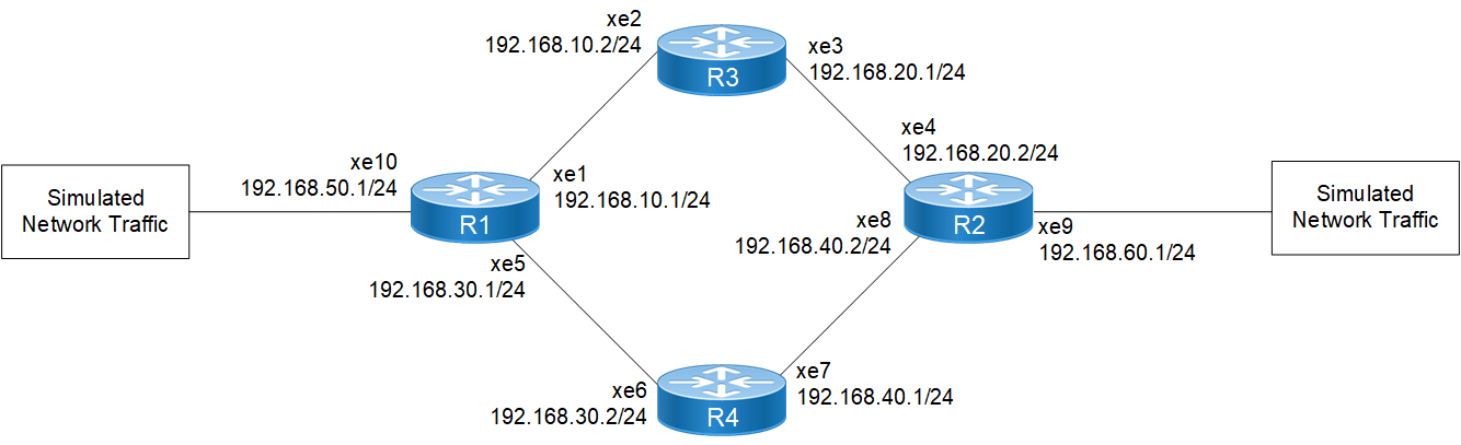
Configure Overload Bit Wait-for-BGP
The key element in these configurations is on R3 and R4, where the set-overload-bit on-startup wait-for-bgp commands are used. By configuring R3 and R4 with these commands, IS-IS on R3 and R4 will advertise the overload bit to its neighbors, effectively informing them not to route traffic through R3 and R4 until BGP has converged. This behavior helps prevent routing anomalies during network restarts and enhances network stability.
R1
Step 1: Assign IP addresses to the interfaces.
R1#configure terminal | Enters configure mode. |
R1(config)#interface xe1 | Configures interface xe1 and enters interface mode. |
R1(config-if)#ip address 192.168.10.1/24 | Assigns the IP address 192.168.10.1/24. |
R1(config-if)#commit | Commits the candidate configuration to the running configuration. |
R1(config-if)#exit | Exits interface mode and returns to the configure mode. |
R1(config)#interface xe5 | Configures interface xe5 and enters interface mode. |
R1(config-if)#ip address 192.168.30.1/24 | Assigns the IP address 192.168.30.1/24. |
R1(config-if)#commit | Commits the candidate configuration to the running configuration. |
R1(config-if)#exit | Exits interface mode and returns to the configure mode. |
R1(config)#interface xe10 | Configures interface xe10 and enters interface mode. |
R1(config-if)#ip address 192.168.50.1/24 | Assigns the IP address 192.168.50.1/24. |
R1(config-if)#commit | Commits the candidate configuration to the running configuration. |
R1(config-if)#exit | Exits interface mode and return to the configure mode. |
Step 2: Configure IS-IS operations.
R1(config)#router isis test | Enters IS-IS router mode for IS-IS process named test. |
R1(config-router)#is-type level-2-only | Specifies IS-IS to operate as Level-2. |
R1(config-router)#bfd all-interfaces | Enables BFD on all interfaces. |
R1(config-router)#net 49.0000.0000.0001.00 | Configures IS-IS network entity title. |
R1(config-router)#redistribute connected | Redistributes connected routes into IS-IS. |
R1(config-router)#commit | Commits the candidate configuration to the running configuration. |
R1(config-router)#exit | Exits IS-IS router mode and returns to the configure mode. |
Step 3: Configure interfaces to participate in IS-IS process.
R1(config)#interface xe1 | Configures interface xe1 and enters interface mode. |
R1(config-if)#ip router isis test | Enables IS-IS IPv4 routing on the interface xe1. |
R1(config-if)#commit | Commits the candidate configuration to the running configuration. |
R1(config-if)#exit | Exits interface mode and returns to the configure mode. |
R1(config)#interface xe5 | Configures interface xe5 and enters interface mode. |
R1(config-if)#ip router isis test | Enables IS-IS IPv4 routing on the interface xe5. |
R1(config-if)#commit | Commits the candidate configuration to the running configuration. |
R1(config-if)#exit | Exits interface mode and returns to the configure mode. |
Step 4: Configure a route map and set the weight within the route map.
R1(config)#route-map rmap1 permit 10 | Configures a route map named rmap1 with a permit statement and enters route-map mode. |
R1(config-route-map)#set weight 4000 | Sets the weight to 4000 in the route map. |
R1(config-route-map)#commit | Commits the candidate configuration to the running configuration. |
R1(config-route-map)#exit | Exits route-map mode and returns to the configure mode. |
Step 5: Configure and activate BGP neighbors, and apply the route map to BGP neighbors for both inbound and outbound traffic.
R1(config)#router bgp 100 | Enters BGP router mode with AS number 100. |
R1(config-router)#neighbor 192.168.10.2 remote-as 300 | Configures BGP neighbors with remote AS number 300. |
R1(config-router)#neighbor 192.168.30.2 remote-as 400 | Configures BGP neighbors with remote AS number 400. |
R1(config-router)#neighbor 192.168.50.2 remote-as 500 | Configures BGP neighbors with remote AS number 500. |
R1(config-router)#address-family ipv4 unicast | Enters BGP address family mode for IPv4 unicast. |
R1(config-router-af)#redistribute connected | Redistributes connected routes into BGP. |
R1(config-router-af)#neighbor 192.168.10.2 activate | Activates BGP neighbors. |
R1(config-router-af)#neighbor 192.168.10.2 route-map rmap1 in | Applies the route-map rmap1 to BGP neighbors for inbound traffic. |
R1(config-router-af)#neighbor 192.168.10.2 route-map rmap1 out | Applies the route-map rmap1 to BGP neighbors for outbound traffic. |
R1(config-router-af)#neighbor 192.168.30.2 activate | Activates BGP neighbors. |
R1(config-router-af)#neighbor 192.168.50.2 activate | Activates BGP neighbors. |
R1(config-router-af)#exit-address-family | Exits BGP address family mode. |
R1(config-router)#commit | Commits the candidate configuration to the running configuration. |
R1(config-router)#exit | Exits BGP router mode and returns to the configure mode. |
R2
Step 1: Assign IP addresses to the interfaces.
R2#configure terminal | Enters configure mode. |
R2(config)#interface xe4 | Configures interface xe4 and enters interface mode. |
R2(config-if)#ip address 192.168.20.2/24 | Assigns the IP address 192.168.20.2/24. |
R2(config-if)#commit | Commits the candidate configuration to the running configuration. |
R2(config-if)#exit | Exits interface mode and returns to the configure mode. |
R2(config)#interface xe8 | Configures interface xe8 and enters interface mode. |
R2(config-if)#ip address 192.168.40.2/24 | Assigns the IP address 192.168.40.2/24. |
R2(config-if)#commit | Commits the candidate configuration to the running configuration. |
R2(config-if)#exit | Exits interface mode and returns to the configure mode. |
R2(config)#interface xe9 | Configures interface xe9 and enters interface mode. |
R2(config-if)#ip address 192.168.60.1/24 | Assigns the IP address 192.168.60.1/24. |
R2(config-if)#commit | Commits the candidate configuration to the running configuration. |
R2(config-if)#exit | Exits interface mode and return to the configure mode. |
Step 2: Configure IS-IS IPv4 routing.
R2(config)#router isis test | Enters IS-IS router mode for IS-IS process named test. |
R2(config-router)#is-type level-2-only | Specifies IS-IS to operate as Level-2. |
R2(config-router)#bfd all-interfaces | Enables BFD on all interfaces. |
R2(config-router)#net 50.0000.0000.0002.00 | Configures IS-IS network entity title. |
R2(config-router)#redistribute connected | Redistributes connected routes into IS-IS. |
R2(config-router)#commit | Commits the candidate configuration to the running configuration. |
R2(config-router)#exit | Exits IS-IS router mode and returns to the configure mode. |
Step 3: Enable IS-IS IPv4 routing on the interfaces.
R2(config)#interface xe4 | Configures interface xe4 and enters interface mode. |
R2(config-if)#ip router isis test | Enables IS-IS IPv4 routing on the interface xe4. |
R2(config-if)#commit | Commits the candidate configuration to the running configuration. |
R2(config-if)#exit | Exits interface mode and returns to the configure mode. |
R2(config)#interface xe8 | Configures interface xe8 and enters interface mode. |
R2(config-if)#ip router isis test | Enables IS-IS IPv4 routing on the interface xe8. |
R2(config-if)#commit | Commits the candidate configuration to the running configuration. |
R2(config-if)#exit | Exits interface mode and returns to the configure mode. |
Step 4: Configure a route map and set the weight within the route map.
R2(config)#route-map rmap1 permit 10 | Configures a route map named rmap1 with a permit statement and enters route-map mode. |
R2(config-route-map)#set weight 4000 | Sets the weight to 4000 in the route map. |
R2(config-route-map)#commit | Commits the candidate configuration to the running configuration. |
R2(config-route-map)#exit | Exits route-map mode and returns to the configure mode. |
Step 5: Configure and activate BGP neighbors, and apply the route map to BGP neighbors for both inbound and outbound traffic.
R2(config)#router bgp 200 | Enters BGP router mode with AS number 200. |
R2(config-router)#neighbor 192.168.20.1 remote-as 300 | Configures BGP neighbors with remote AS number 300. |
R2(config-router)#neighbor 192.168.40.1 remote-as 400 | Configures BGP neighbors with remote AS number 400. |
R2(config-router)#neighbor 192.168.60.2 remote-as 600 | Configures BGP neighbors with remote AS number 600. |
R2(config-router)#address-family ipv4 unicast | Enters BGP address family mode for IPv4 unicast. |
R2(config-router-af)#redistribute connected | Redistributes connected routes into BGP. |
R2(config-router-af)#neighbor 192.168.20.1 activate | Activates BGP neighbors. |
R2(config-router-af)#neighbor 192.168.20.1 route-map rmap1 in | Applies the route-map rmap1 to BGP neighbors for inbound traffic. |
R2(config-router-af)#neighbor 192.168.20.1 route-map rmap1 out | Applies the route-map rmap1 to BGP neighbors for outbound traffic. |
R2(config-router-af)#neighbor 192.168.40.1 activate | Activates BGP neighbors. |
R2(config-router-af)#neighbor 192.168.60.2 activate | Activates BGP neighbors. |
R2(config-router-af)#exit-address-family | Exits BGP address family mode. |
R2(config-router)#commit | Commits the candidate configuration to the running configuration. |
R2(config-router)#exit | Exits BGP router mode and returns to the configure mode. |
R3
Step 1: Assign IP addresses to the interfaces.
R3#configure terminal | Enters configure mode. |
R3(config)#interface xe2 | Configures interface xe2 and enters interface mode. |
R3(config-if)#ip address 192.168.10.2/24 | Assigns the IP address 192.168.10.2/24. |
R3(config-if)#commit | Commits the candidate configuration to the running configuration. |
R3(config-if)#exit | Exits interface mode and returns to the configure mode. |
R3(config)#interface xe3 | Configures interface xe3 and enters interface mode. |
R3(config-if)#ip address 192.168.20.1/24 | Assigns the IP address 192.168.20.1/24. |
R3(config-if)#commit | Commits the candidate configuration to the running configuration. |
R3(config-if)#exit | Exits interface mode and returns to the configure mode. |
Step 2: Configure IS-IS IPv4 routing, setting the overload bit on startup and waiting for BGP convergence.
R3(config)#router isis test | Enters IS-IS router mode for IS-IS process named test. |
R3(config-router)#is-type level-2-only | Specifies IS-IS to operate as Level-2. |
R3(config-router)#set-overload-bit on-startup wait-for-bgp | Configures the overload bit to be set on startup and wait for BGP convergence. |
R3(config-router)#bfd all-interfaces | Enables BFD on all interfaces. |
R3(config-router)#net 51.0000.0000.0003.00 | Configures IS-IS network entity title. |
R3(config-router)#redistribute connected | Redistributes connected routes into IS-IS. |
R3(config-router)#commit | Commits the candidate configuration to the running configuration. |
R3(config-router)#exit | Exits IS-IS router mode and returns to the configure mode. |
Step 3: Enable IS-IS IPv4 routing on the interfaces.
R3(config)#interface xe2 | Configures interface xe2 and enters interface mode. |
R3(config-if)#ip router isis test | Enables IS-IS IPv4 routing on the interface xe2. |
R3(config-if)#commit | Commits the candidate configuration to the running configuration. |
R3(config-if)#exit | Exits interface mode and returns to the configure mode. |
R3(config)#interface xe3 | Configures interface xe3 and enters interface mode. |
R3(config-if)#ip router isis test | Enables IS-IS IPv4 routing on the interface xe3. |
R3(config-if)#commit | Commits the candidate configuration to the running configuration. |
R3(config-if)#exit | Exits interface mode and returns to the configure mode. |
Step 4: Configure and activate BGP neighbors.
R3(config)#router bgp 300 | Enters BGP router mode with AS number 300. |
R3(config-router)#neighbor 192.168.10.1 remote-as 100 | Configures BGP neighbors with remote AS number 100. |
R3(config-router)#neighbor 192.168.20.2 remote-as 200 | Configures BGP neighbors with remote AS number 200. |
R3(config-router)#address-family ipv4 unicast | Enters BGP address family mode for IPv4 unicast. |
R3(config-router-af)#redistribute connected | Redistributes connected routes into BGP. |
R3(config-router-af)#neighbor 192.168.10.1 activate | Activates BGP neighbors. |
R3(config-router-af)#neighbor 192.168.20.2 activate | Activates BGP neighbors. |
R3(config-router-af)#exit-address-family | Exits BGP address family mode. |
R3(config-router)#commit | Commits the candidate configuration to the running configuration. |
R3(config-router)#exit | Exits BGP router mode and returns to the configure mode. |
R4
Step 1: Assign IP addresses to the interfaces.
R4#configure terminal | Enters configure mode. |
R4(config)#interface xe6 | Configures interface xe6 and enters interface mode. |
R4(config-if)#ip address 192.168.30.2/24 | Assigns the IP address 192.168.30.2/24. |
R4(config-if)#commit | Commits the candidate configuration to the running configuration. |
R4(config-if)#exit | Exits interface mode and returns to the configure mode. |
R4(config)#interface xe7 | Configures interface xe7 and enters interface mode. |
R4(config-if)#ip address 192.168.40.1/24 | Assigns the IP address 192.168.40.1/24. |
R4(config-if)#commit | Commits the candidate configuration to the running configuration. |
R4(config-if)#exit | Exits interface mode and returns to the configure mode. |
Step 2: Configure IS-IS IPv4 routing, setting the overload bit on startup and waiting for BGP convergence.
R4(config)#router isis test | Enters IS-IS router mode for IS-IS process named test. |
R4(config-router)#is-type level-2-only | Specifies IS-IS to operate as Level-2. |
R4(config-router)#bfd all-interfaces | Enables BFD on all interfaces. |
R4(config-router)#net 52.0000.0000.0004.00 | Configures IS-IS network entity title. |
R4(config-router)#redistribute connected | Redistributes connected routes into IS-IS. |
R4(config-router)#commit | Commits the candidate configuration to the running configuration. |
R4(config-router)#exit | Exits IS-IS router mode and returns to the configure mode. |
Step 3: Enable IS-IS IPv4 routing on the interfaces.
R4(config)#interface xe6 | Configures interface xe6 and enters interface mode. |
R4(config-if)#ip router isis test | Enables IS-IS IPv4 routing on the interface xe6. |
R4(config-if)#commit | Commits the candidate configuration to the running configuration. |
R4(config-if)#exit | Exits interface mode and returns to the configure mode. |
R4(config)#interface xe7 | Configures interface xe7 and enters interface mode. |
R4(config-if)#ip router isis test | Enables IS-IS IPv4 routing on the interface xe7. |
R4(config-if)#commit | Commits the candidate configuration to the running configuration. |
R4(config-if)#exit | Exits interface mode and returns to the configure mode. |
Step 4: Configure and activate BGP neighbors.
R4(config)#router bgp 400 | Enters BGP router mode with AS number 400. |
R4(config-router)#neighbor 192.168.30.1 remote-as 100 | Configures BGP neighbors with remote AS number 100. |
R4(config-router)#neighbor 192.168.40.2 remote-as 200 | Configures BGP neighbors with remote AS number 200. |
R4(config-router)#address-family ipv4 unicast | Enters BGP address family mode for IPv4 unicast. |
R4(config-router-af)#redistribute connected | Redistributes connected routes into BGP. |
R4(config-router-af)#neighbor 192.168.30.1 activate | Activates BGP neighbors. |
R4(config-router-af)#neighbor 192.168.40.2 activate | Activates BGP neighbors. |
R4(config-router-af)#exit-address-family | Exits BGP address family mode. |
R4(config-router)#commit | Commits the candidate configuration to the running configuration. |
R4(config-router)#exit | Exits BGP router mode and returns to the configure mode. |
Validation
1. Verify the ISIS and BGP sessions are coming up.
2. Send traffic from one network simulator to another and verify traffic flow via R1-R3-R2 router’s without loss.
3. Reload R3 router.
4. Verify traffic switchover to the R1-R4-R2 routers path.
5. Unconfigure the BGP neighbor between R2 and R3 routers during R2 routers reload.
6. After reloading, check the overload-bit is set to 1 (0/0/1) on the R3 router using the show isis database command.
7. Now configure the BGP neighbor between R2 and R3 routers and verify the BGP session comes up.
8. After some time, verify the overload-bit is set to 0 (0/0/0) using the show isis database command on the R3 router.
9. Verify traffic switchover to the R1-R3-R2 router’s path.
Before Reload
R3#show interface counters rate mbps
+-------------------+--------------+-------------+--------------+-------------+
| Interface | Rx mbps | Rx pps | Tx mbps | Tx pps |
+-------------------+--------------+-------------+--------------+-------------+
xe4 680.47 664526 0.01 4
xe5 0.00 4 680.48 664525
R3#reload
Are you sure you would like to reset the system? (y/n): y
Device rebooted by ocnos user from cmlsh at time:Thu Dec 7 11:45:40 2023
R3# Stopping xinetd service...
[ OK ] Stopped target Timers.
[ OK ] Stopped Daily rotation of log files.
[ OK ] Stopped Daily Cleanup of Temporary Directories.
After Reload
R3
R3#show interface counters rate mbps
+-------------------+--------------+-------------+--------------+-------------+
| Interface | Rx mbps | Rx pps | Tx mbps | Tx pps |
+-------------------+--------------+-------------+--------------+-------------+
xe4 0.00 4 0.01 5
xe5 0.00 4 0.01 4
R3#show isis database
Tag test: VRF : default
IS-IS Level-2 Link State Database:
LSPID LSP Seq Num LSP Checksum LSP Holdtime ATT/P/OL
0000.0000.0001.00-00 0x00000057 0xDE86 1130 0/0/0
0000.0000.0002.00-00 0x00000056 0x7E6E 1130 0/0/0
0000.0000.0003.00-00* 0x00000055 0x55C5 1131 0/0/1
0000.0000.0003.01-00* 0x00000005 0x25AD 1132 0/0/0
0000.0000.0003.02-00* 0x0000004A 0x7A13 1132 0/0/0
0000.0000.0004.00-00 0x00000051 0x20C2 574 0/0/0
0000.0000.0004.01-00 0x0000004C 0x9CEC 466 0/0/0
0000.0000.0004.02-00 0x00000049 0x820A 467 0/0/0
R4
R4#show interface counters rate mbps
+-------------------+--------------+-------------+--------------+-------------+
| Interface | Rx mbps | Rx pps | Tx mbps | Tx pps |
+-------------------+--------------+-------------+--------------+-------------+
ge1 0.00 4 691.93 675712
xe8 691.93 675712 0.01 4
R2
R2(config-router)#no neighbor 192.168.20.1 remote-as 300
R2(config-router)#commit
R2#
R2#config t
R2(config)#router bgp 200
R2(config-router)#neighbor 192.168.20.1 remote-as 300
R2(config-router)#address-family ipv4 unicast
R2(config-router-af)#neighbor 192.168.20.1 activate
R2(config-router-af)#neighbor 192.168.20.1 route-map rmap1 in
R2(config-router-af)#neighbor 192.168.20.1 route-map rmap1 out
R2(config-router-af)#exit-address-family
R3
R3#show isis database
Tag test: VRF : default
IS-IS Level-2 Link State Database:
LSPID LSP Seq Num LSP Checksum LSP Holdtime ATT/P/OL
0000.0000.0001.00-00 0x00000057 0xDE86 1092 0/0/0
0000.0000.0002.00-00 0x00000056 0x7E6E 1092 0/0/0
0000.0000.0003.00-00* 0x00000056 0x4FCE 1191 0/0/0
0000.0000.0003.01-00* 0x00000005 0x25AD 1094 0/0/0
0000.0000.0003.02-00* 0x0000004A 0x7A13 1094 0/0/0
0000.0000.0004.00-00 0x00000051 0x20C2 536 0/0/0
0000.0000.0004.01-00 0x0000004C 0x9CEC 428 0/0/0
0000.0000.0004.02-00 0x00000049 0x820A 429 0/0/0
R3#show interface counters rate mbps
+-------------------+--------------+-------------+--------------+-------------+
| Interface | Rx mbps | Rx pps | Tx mbps | Tx pps |
+-------------------+--------------+-------------+--------------+-------------+
xe4 681.59 665618 0.01 4
xe5 0.00 4 681.60 665618
Suppress External and Interlevel Reachability
The control mechanism of suppressing the redistribution of external, interlevel, or both external and interlevel reachabilities is useful for managing the advertisement of these specific reachability data during overload states, providing flexibility in network configurations.
Topology
Figure 14-113 represents a sample topology with three routers (R1, R2, and R3) interconnected in a linear sequence.

Configure Overload Bit Suppress
The key element in the below configurations is on R3 router, where the set-overload-bit suppress external and set-overload-bit suppress interlevel commands are used.
Configuring the R3 router with the set-overload-bit suppress external or set-overload-bit suppress interlevel commands in IS-IS prevents the advertisement of external routes learned from BGP to its ISIS neighbors or prevents the advertisement of interlevel routes to its ISIS neighbors. The options suppress external or suppress interlevel contribute to the controlled management of routing information during network overload states.
R1
Step 1: Assign IP addresses to the interfaces.
R1#configure terminal | Enters configure mode. |
R1(config)#interface xe1 | Configures interface xe1 and enters interface mode. |
R1(config-if)#ip address 192.168.10.1/24 | Assigns the IP address 192.168.10.1/24. |
R1(config-if)#commit | Commits the candidate configuration to the running configuration. |
R1(config-if)#exit | Exits interface mode and returns to the configure mode. |
Step 2: Configure IS-IS operations.
R1(config)#router isis test | Enters IS-IS router mode for IS-IS process named test. |
R1(config-router)#is-type level-1 | Specifies IS-IS to operate as Level-1. |
R1(config-router)#bfd all-interfaces | Enables BFD on all interfaces. |
R1(config-router)#net 49.0000.0000.0001.00 | Configures IS-IS network entity title. |
R1(config-router)#redistribute connected | Redistributes connected routes into IS-IS. |
R1(config-router)#commit | Commits the candidate configuration to the running configuration. |
R1(config-router)#exit | Exits IS-IS router mode and returns to the configure mode. |
Step 3: Configure interfaces to participate in IS-IS process.
R1(config)#interface xe1 | Configures interface xe1 and enters interface mode. |
R1(config-if)#ip router isis test | Enables IS-IS IPv4 routing on the interface xe1. |
R1(config-if)#commit | Commits the candidate configuration to the running configuration. |
R1(config-if)#exit | Exits interface mode and returns to the configure mode. |
R1(config)#interface lo | Configures a loopback interface lo and enters interface mode. |
R1(config-if)#ip address 1.1.1.1/32 secondary | Assigns the secondary IP address 1.1.1.1/32. |
R1(config-if)#ip router isis test | Enables IS-IS IPv4 routing on the loopback interface lo. |
R1(config-if)#commit | Commits the candidate configuration to the running configuration. |
R1(config-if)#exit | Exits interface mode and returns to the configure mode. |
Step 4: Configure and activate BGP neighbors
Note: Configure BGP only for Suppress External reachability using the set-overload-bit suppress external command, excluding interlevel reachability.
R1(config)#router bgp 100 | Enters BGP router mode with AS number 100. |
R1(config-router)#neighbor 192.168.10.2 remote-as 300 | Configures BGP neighbors with remote AS number 300. |
R1(config-router)#address-family ipv4 unicast | Enters BGP address family mode for IPv4 unicast. |
R1(config-router-af)#redistribute connected | Redistributes connected routes into BGP. |
R1(config-router-af)#neighbor 192.168.10.2 activate | Activates BGP neighbors. |
R1(config-router-af)#exit-address-family | Exits BGP address family mode. |
R1(config-router)#commit | Commits the candidate configuration to the running configuration. |
R1(config-router)#exit | Exits BGP router mode and returns to the configure mode. |
R2
Step 1: Assign IP addresses to the interfaces.
R2#configure terminal | Enters configure mode. |
R2(config)#interface xe4 | Configures interface xe4 and enters interface mode. |
R2(config-if)#ip address 192.168.20.2/24 | Assigns the IP address 192.168.20.2/24. |
R2(config-if)#commit | Commits the candidate configuration to the running configuration. |
R2(config-if)#exit | Exits interface mode and returns to the configure mode. |
Step 2: Configure IS-IS IPv4 routing.
R2(config)#router isis test | Enters IS-IS router mode for IS-IS process named test. |
R2(config-router)#is-type level-1 | Specifies IS-IS to operate as Level-1. |
R2(config-router)#bfd all-interfaces | Enables BFD on all interfaces. |
R2(config-router)#net 49.0000.0000.0002.00 | Configures IS-IS network entity title. |
R2(config-router)#redistribute connected | Redistributes connected routes into IS-IS. |
R2(config-router)#commit | Commits the candidate configuration to the running configuration. |
R2(config-router)#exit | Exits IS-IS router mode and returns to the configure mode. |
Step 3: Enable IS-IS IPv4 routing on the interfaces.
R2(config)#interface xe4 | Configures interface xe4 and enters interface mode. |
R2(config-if)#ip router isis test | Enables IS-IS IPv4 routing on the interface xe4. |
R2(config-if)#commit | Commits the candidate configuration to the running configuration. |
R2(config-if)#exit | Exits interface mode and returns to the configure mode. |
R2(config)#interface lo | Configures a loopback interface lo and enters interface mode. |
R2(config-if)#ip address 2.2.2.2/32 secondary | Assigns the secondary IP address 2.2.2.2/32. |
R2(config-if)#ip router isis test | Enables IS-IS IPv4 routing on the loopback interface lo. |
R2(config-if)#commit | Commits the candidate configuration to the running configuration. |
R2(config-if)#exit | Exits interface mode and returns to the configure mode. |
R3
Step 1: Assign IP addresses to the interfaces
R3#configure terminal | Enters configure mode. |
R3(config)#interface xe2 | Configures interface xe2 and enters interface mode. |
R3(config-if)#ip address 192.168.10.2/24 | Assigns the IP address 192.168.10.2/24. |
R3(config-if)#commit | Commits the candidate configuration to the running configuration. |
R3(config-if)#exit | Exits interface mode and returns to the configure mode. |
R3(config)#interface xe3 | Configures interface xe3 and enters interface mode. |
R3(config-if)#ip address 192.168.20.1/24 | Assigns the IP address 192.168.20.1/24. |
R3(config-if)#commit | Commits the candidate configuration to the running configuration. |
R3(config-if)#exit | Exits interface mode and returns to the configure mode. |
Step 2: Configure IS-IS IPv4 routing, setting the overload bit suppress external or interlevel options.
R3(config)#router isis test | Enters IS-IS router mode for IS-IS process named test. |
R3(config-router)#is-type level-2-only | Specifies IS-IS to operate as Level-2. |
R3(config-router)#set-overload-bit suppress external OR R3(config-router)#set-overload-bit suppress interlevel | Suppresses the redistribution of external reachability during overload states. OR Suppresses the redistribution of interlevel reachability during overload states. |
R3(config-router)#bfd all-interfaces | Enables BFD on all interfaces. |
R3(config-router)#net 49.0000.0000.0003.00 | Configures the IS-IS network entity title. |
R3(config-router)#redistribute bgp | Redistributes BGP routes into IS-IS. |
R3(config-router)#commit | Commits the candidate configuration to the running configuration. |
R3(config-router)#exit | Exits IS-IS router mode and returns to the configure mode. |
Step 3: Enable IS-IS IPv4 routing on the interfaces
R3(config)#interface xe2 | Configures interface xe2 and enters interface mode. |
R3(config-if)#ip router isis test | Enables IS-IS IPv4 routing on the interface xe2. |
R3(config-if)#commit | Commits the candidate configuration to the running configuration. |
R3(config-if)#exit | Exits interface mode and returns to the configure mode. |
R3(config)#interface xe3 | Configures interface xe3 and enters interface mode. |
R3(config-if)#ip router isis test | Enables IS-IS IPv4 routing on the interface xe3. |
R3(config-if)#commit | Commits the candidate configuration to the running configuration. |
R3(config-if)#exit | Exits interface mode and returns to the configure mode. |
R3(config)#interface lo | Configures a loopback interface lo and enters interface mode. |
R3(config-if)#ip address 3.3.3.3/32 secondary | Assigns the secondary IP address 3.3.3.3/32. |
R3(config-if)#ip router isis test | Enables IS-IS IPv4 routing on the loopback interface lo. |
R3(config-if)#commit | Commits the candidate configuration to the running configuration. |
R3(config-if)#exit | Exits interface mode and returns to the configure mode. |
Step 4: Configure and activate BGP neighbors
Note: Configure BGP only for Suppress External reachability using the set-overload-bit suppress external command, excluding interlevel reachability.
R3(config)#router bgp 300 | Enters BGP router mode with AS number 300. |
R3(config-router)#neighbor 192.168.10.1 remote-as 100 | Configures BGP neighbors with remote AS number 100. |
R3(config-router)#address-family ipv4 unicast | Enters BGP address family mode for IPv4 unicast. |
R3(config-router-af)#redistribute connected | Redistributes connected routes into BGP. |
R3(config-router-af)#neighbor 192.168.10.1 activate | Activates BGP neighbors. |
R3(config-router-af)#exit-address-family | Exits BGP address family mode. |
R3(config-router)#commit | Commits the candidate configuration to the running configuration. |
R3(config-router)#exit | Exits BGP router mode and returns to the configure mode. |
Validation
Verify all IS-IS sessions are up.
Pre-Configuration Check: ISIS Session Status
Before configuring set-overload-bit suppress external command, verify the ISIS session status on R1, R2, and R3 routers.
R1#show ip route
Codes: K - kernel, C - connected, S - static, R - RIP, B - BGP
O - OSPF, IA - OSPF inter area
N1 - OSPF NSSA external type 1, N2 - OSPF NSSA external type 2
E1 - OSPF external type 1, E2 - OSPF external type 2
i - IS-IS, L1 - IS-IS level-1, L2 - IS-IS level-2,
ia - IS-IS inter area, E - EVPN,
v - vrf leaked
* - candidate default
IP Route Table for VRF "default"
C 1.1.1.1/32 is directly connected, lo, 00:13:54
i L1 2.2.2.2/32 [115/20] via 192.168.10.2, xe2, 00:01:46
i L1 3.3.3.3/32 [115/30] via 192.168.10.2, xe2, 00:00:06
C 127.0.0.0/8 is directly connected, lo, 00:13:54
C 192.168.10.0/24 is directly connected, xe1, 00:13:54
i L1 192.168.20.0/24 [115/20] via 192.168.10.2, xe2, 00:01:46
Gateway of last resort is not set
R3#show ip route
Codes: K - kernel, C - connected, S - static, R - RIP, B - BGP
O - OSPF, IA - OSPF inter area
N1 - OSPF NSSA external type 1, N2 - OSPF NSSA external type 2
E1 - OSPF external type 1, E2 - OSPF external type 2
i - IS-IS, L1 - IS-IS level-1, L2 - IS-IS level-2,
ia - IS-IS inter area, E - EVPN,
v - vrf leaked
* - candidate default
IP Route Table for VRF "default"
i L1 1.1.1.1/32 [115/30] via 192.168.10.1, xe1, 00:01:19
i L1 2.2.2.2/32 [115/20] via 192.168.20.2, xe4, 00:06:49
C 3.3.3.3/32 is directly connected, lo, 00:25:23
C 127.0.0.0/8 is directly connected, lo, 00:25:23
i L1 192.168.10.0/24 is directly connected, xe2, 00:06:49
C 192.168.20.0/24 is directly connected, xe3, 00:25:23
Gateway of last resort is not set
R2#show ip route
Codes: K - kernel, C - connected, S - static, R - RIP, B - BGP
O - OSPF, IA - OSPF inter area
N1 - OSPF NSSA external type 1, N2 - OSPF NSSA external type 2
E1 - OSPF external type 1, E2 - OSPF external type 2
i - IS-IS, L1 - IS-IS level-1, L2 - IS-IS level-2,
ia - IS-IS inter area, E - EVPN,
v - vrf leaked
* - candidate default
IP Route Table for VRF "default"
B 1.1.1.1/32 [20/0] via 192.168.20.1, xe3, 00:00:05
C 2.2.2.2/32 is directly connected, lo, 00:25:20
i L1 3.3.3.3/32 [115/20] via 192.168.20.1, xe3, 00:06:46
C 127.0.0.0/8 is directly connected, lo, 00:25:20
C 192.168.10.0/24 [100/23] via 192.168.20.1, xe3, 00:25:20
C 192.168.20.0/24 is directly connected, xe4, 00:25:20
Gateway of last resort is not set
Before configuring set-overload-bit suppress interlevel command, verify the ISIS session status on R1, R2, and R3 routers.
R1#show ip route
Codes: K - kernel, C - connected, S - static, R - RIP, B - BGP
O - OSPF, IA - OSPF inter area
N1 - OSPF NSSA external type 1, N2 - OSPF NSSA external type 2
E1 - OSPF external type 1, E2 - OSPF external type 2
i - IS-IS, L1 - IS-IS level-1, L2 - IS-IS level-2,
ia - IS-IS inter area, E - EVPN,
v - vrf leaked
* - candidate default
IP Route Table for VRF "default"
C 1.1.1.1/32 is directly connected, lo, 00:14:58
i L1 2.2.2.2/32 [115/20] via 192.168.10.2, xe2, 00:02:50
i L1 3.3.3.3/32 [115/30] via 192.168.10.2, xe2, 00:01:10
C 127.0.0.0/8 is directly connected, lo, 00:14:58
C 192.168.10.0/24 is directly connected, xe1, 00:14:58
i L1 192.168.20.0/24 [115/20] via 192.168.10.2, xe2, 00:02:50
Gateway of last resort is not set
R3#show ip route
Codes: K - kernel, C - connected, S - static, R - RIP, B - BGP
O - OSPF, IA - OSPF inter area
N1 - OSPF NSSA external type 1, N2 - OSPF NSSA external type 2
E1 - OSPF external type 1, E2 - OSPF external type 2
i - IS-IS, L1 - IS-IS level-1, L2 - IS-IS level-2,
ia - IS-IS inter area, E - EVPN,
v - vrf leaked
* - candidate default
IP Route Table for VRF "default"
i L1 1.1.1.1/32 [115/30] via 192.168.10.1, xe1, 00:01:19
i L1 2.2.2.2/32 [115/20] via 192.168.20.21, xe4, 00:06:49
C 3.3.3.3/32 is directly connected, lo, 00:25:23
C 127.0.0.0/8 is directly connected, lo, 00:25:23
i L1 192.168.10.0/24 is directly connected, xe2, 00:06:49
C 192.168.20.0/24 is directly connected, xe3, 00:25:23
Gateway of last resort is not set
R2#show ip route
Codes: K - kernel, C - connected, S - static, R - RIP, B - BGP
O - OSPF, IA - OSPF inter area
N1 - OSPF NSSA external type 1, N2 - OSPF NSSA external type 2
E1 - OSPF external type 1, E2 - OSPF external type 2
i - IS-IS, L1 - IS-IS level-1, L2 - IS-IS level-2,
ia - IS-IS inter area, E - EVPN,
v - vrf leaked
* - candidate default
IP Route Table for VRF "default"
i L1 1.1.1.1/32 [115/20] via 192.168.20.1, xe3, 00:06:41
C 2.2.2.2/32 is directly connected, lo, 00:25:15
i L1 3.3.3.3/32 [115/20] via 192.168.20.1, xe3, 00:06:41
C 127.0.0.0/8 is directly connected, lo, 00:25:15
C 192.168.10.0/24 [115/20] via 192.168.20.1, xe3, 00:25:15
C 192.168.20.0/24 is directly connected, xe4, 00:25:15
Gateway of last resort is not set
Post-Configuration Check: ISIS Session Status
After configuring set-overload-bit suppress external command, verify the ISIS session status on R1, R2, and R3 routers.
R1#show ip route
Codes: K - kernel, C - connected, S - static, R - RIP, B - BGP
O - OSPF, IA - OSPF inter area
N1 - OSPF NSSA external type 1, N2 - OSPF NSSA external type 2
E1 - OSPF external type 1, E2 - OSPF external type 2
i - IS-IS, L1 - IS-IS level-1, L2 - IS-IS level-2,
ia - IS-IS inter area, E - EVPN,
v - vrf leaked
* - candidate default
IP Route Table for VRF "default"
C 1.1.1.1/32 is directly connected, lo, 00:20:29
i L1 2.2.2.2/32 [115/20] via 192.168.10.2, xe2, 00:01:56
C 127.0.0.0/8 is directly connected, lo, 00:20:29
C 192.168.10.0/24 is directly connected, xe1, 00:20:29
i L1 192.168.20.0/24 [115/20] via 192.168.10.2, xe2, 00:01:56
Gateway of last resort is not set
R3#show ip route
Codes: K - kernel, C - connected, S - static, R - RIP, B - BGP
O - OSPF, IA - OSPF inter area
N1 - OSPF NSSA external type 1, N2 - OSPF NSSA external type 2
E1 - OSPF external type 1, E2 - OSPF external type 2
i - IS-IS, L1 - IS-IS level-1, L2 - IS-IS level-2,
ia - IS-IS inter area, E - EVPN,
v - vrf leaked
* - candidate default
IP Route Table for VRF "default"
i L1 2.2.2.2/32 [115/20] via 192.168.20.2, xe4, 00:07:50
C 3.3.3.3/32 is directly connected, lo, 00:26:24
C 127.0.0.0/8 is directly connected, lo, 00:26:24
i L1 192.168.10.0/24 is directly connected, xe2, 00:07:50
C 192.168.20.0/24 is directly connected, xe3, 00:26:24
Gateway of last resort is not set
R2#show ip route
Codes: K - kernel, C - connected, S - static, R - RIP, B - BGP
O - OSPF, IA - OSPF inter area
N1 - OSPF NSSA external type 1, N2 - OSPF NSSA external type 2
E1 - OSPF external type 1, E2 - OSPF external type 2
i - IS-IS, L1 - IS-IS level-1, L2 - IS-IS level-2,
ia - IS-IS inter area, E - EVPN,
v - vrf leaked
* - candidate default
IP Route Table for VRF "default"
B 1.1.1.1/32 [20/0] via 192.168.20.1, xe3, 00:00:03
C 2.2.2.2/32 is directly connected, lo, 00:25:18
i L1 3.3.3.3/32 [115/20] via 192.168.20.1, xe3, 00:06:44
C 127.0.0.0/8 is directly connected, lo, 00:25:18
C 192.168.10.0/24 [100/10] via 192.168.20.1, xe3, 00:25:18
C 192.168.20.0/24 is directly connected, xe4, 00:25:18
Gateway of last resort is not set
After configuring set-overload-bit suppress interlevel command, verify the ISIS session status on R1, R2, and R3 routers.
R1#show ip route
Codes: K - kernel, C - connected, S - static, R - RIP, B - BGP
O - OSPF, IA - OSPF inter area
N1 - OSPF NSSA external type 1, N2 - OSPF NSSA external type 2
E1 - OSPF external type 1, E2 - OSPF external type 2
i - IS-IS, L1 - IS-IS level-1, L2 - IS-IS level-2,
ia - IS-IS inter area, E - EVPN,
v - vrf leaked
* - candidate default
IP Route Table for VRF "default"
C 1.1.1.1/32 is directly connected, lo, 00:14:58
i L1 2.2.2.2/32 [115/20] via 192.168.10.2, xe2, 00:02:50
C 127.0.0.0/8 is directly connected, lo, 00:14:58
C 192.168.10.0/24 is directly connected, xe1, 00:14:58
i L1 192.168.20.0/24 [115/20] via 192.168.10.2, xe2, 00:02:50
Gateway of last resort is not set
R3#show ip route
Codes: K - kernel, C - connected, S - static, R - RIP, B - BGP
O - OSPF, IA - OSPF inter area
N1 - OSPF NSSA external type 1, N2 - OSPF NSSA external type 2
E1 - OSPF external type 1, E2 - OSPF external type 2
i - IS-IS, L1 - IS-IS level-1, L2 - IS-IS level-2,
ia - IS-IS inter area, E - EVPN,
v - vrf leaked
* - candidate default
IP Route Table for VRF "default"
i L1 1.1.1.1/32 [115/30] via 192.168.10.1, xe1, 00:01:19
i L1 2.2.2.2/32 [115/20] via 192.168.20.2, xe4, 00:06:49
C 3.3.3.3/32 is directly connected, lo, 00:25:23
C 127.0.0.0/8 is directly connected, lo, 00:25:23
i L1 192.168.10.0/24 is directly connected, xe2, 00:06:49
C 192.168.20.0/24 is directly connected, xe3, 00:25:23
Gateway of last resort is not set
R2#show ip route
Codes: K - kernel, C - connected, S - static, R - RIP, B - BGP
O - OSPF, IA - OSPF inter area
N1 - OSPF NSSA external type 1, N2 - OSPF NSSA external type 2
E1 - OSPF external type 1, E2 - OSPF external type 2
i - IS-IS, L1 - IS-IS level-1, L2 - IS-IS level-2,
ia - IS-IS inter area, E - EVPN,
v - vrf leaked
* - candidate default
IP Route Table for VRF "default"
C 2.2.2.2/32 is directly connected, lo, 00:25:15
i L1 3.3.3.3/32 [115/20] via 192.168.20.1, xe3, 00:06:41
C 127.0.0.0/8 is directly connected, lo, 00:25:15
C 192.168.10.0/24 [115/20] via 192.168.20.1, xe3, 00:25:15
C 192.168.20.0/24 is directly connected, xe4, 00:25:15
Gateway of last resort is not set
Passive Interface
In ISP and large enterprise networks, many of the distribution routers have more than 200 interfaces. Before the Default Passive-Interface feature, there were two possibilities for obtaining routing information from all of these interfaces:
• Configure a routing protocol on the backbone interfaces and redistribute connected interfaces.
• Configure the routing protocol on all interfaces and manually set most of them as passive, which was time consuming.
The solution to this problem was to configure the routing protocol on all interfaces and manually set the passive-interface command on the interfaces where adjacency was not desired. In certain networks, this meant coding 200 or more passive-interface statements. With the Default Passive Interface feature, this problem is solved by allowing all interfaces to be set as passive by default using a single passive-interface default command, then configuring individual interfaces in which adjacencies are desired using the passive-interface <interface-name> disable command.
Usage
1. When a specific interface is configured as passive using the passive-interface <interface-name> command:
• The interface loses its adjacency on that interface, for example, eth1.
• The interface (eth1) is still advertised by other IS-IS speaking interfaces to their neighbors.
2. When a specific interface is configured as passive using passive-interface <interface-name> command followed by removing the configuration using no passive-interface <interface-name> command:
• The interface is IS-IS disabled and must be enabled using the ip router isis command (for example, ip router isis 1).
• If IS-IS is not configured, the interface (for example, eth1) will not be advertised by other IS-IS speaking interfaces to their neighbors.
3. When an interface is configured with the passive interface command:
• All IS-IS enabled interfaces lose their adjacency.
• All IS-IS enabled interfaces in the system will be made passive.
• To establish adjacency on a particular interface, the passive interface <interface-name> disable command must be enabled.
• All interfaces which were made passive are advertised by the active IS-IS speaking interface to its neighbors.
4. When an interface is configured with the no passive interface command:
• All interfaces which are currently passive, will become active.
• If IS-IS is configured on those interface, it will start sending out IS-IS packets and attempt to form adjacency.
• If IS-IS is not configured on those interfaces, it will not be advertised by the active IS-IS speaking interface to its neighbors.
Topology
Figure 14-114 shows a passive-interface configuration example.
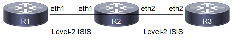
IS-IS Passive Interface
Configuration
R1
#configure terminal | Enter configure mode. |
(config)#router isis 1 | Create an IS-IS routing instance (1). |
(config-router)#net 49.0001.0000.0000.0001.00 | Define the NET address. |
(config-router)#is-type level-2-only | Configure instance as level-2-only routing. |
(config-if)#commit | Commit candidate configuration to the running configuration |
(config-router)#exit | Exit router mode. |
(config)#interface eth1 | Specify the interface (eth1)to configure and enter Interface mode. |
(config-if)#ip address 20.20.20.1/24 | Configure IP address on interface. |
(config-if)#ip router isis 1 | Enable IS-IS routing on interface eth1 (connected to R2). |
(config-if)#commit | Commit candidate configuration to the running configuration |
R2
#configure terminal | Enter configure mode. |
(config)#interface eth1 | Specify the interface (eth1)to configure and enter Interface mode. |
(config-if)#ip address 20.20.20.2/24 | Configure IP address on interface. |
(config-if)#ip router isis 1 | Enable IS-IS routing on interface eth1 (connected to R1). |
(config-if)#exit | Exit interface mode and return to Configure mode. |
(config)#interface eth2 | Specify the interface (eth2)to configure and enter Interface mode. |
(config-if)#ip address 30.30.30.1/24 | Configure IP address on interface. |
(config-if)#ip router isis 1 | Enable IS-IS routing on interface eth2 (connected to R3). |
(config-if)#commit | Commit candidate configuration to the running configuration |
(config-if)#exit | Exit interface mode and return to Configure mode. |
(config)#router isis 1 | Create an IS-IS routing instance (1). |
(config-router)#net 49.0001.0000.0000.0002.00 | Define the NET address. |
(config-router)#is-type level-2-only | Configure instance as level-2-only routing. |
(config-router)#passive-interface eth1 | Configure the eth1 interface as passive. |
R3
#configure terminal | Enter configure mode. |
(config)#router isis 1 | Create an IS-IS routing instance (1). |
(config-router)#is-type level-2-only | Configure instance as level-2-only routing. |
(config-router)#net 49.0001.0000.0000.0003.00 | Define the NET address. |
(config-if)#commit | Commit candidate configuration to the running configuration |
(config-router)#exit | Exit router mode. |
(config)#interface eth2 | Specify the interface (eth2)to configure and enter Interface mode. |
(config-if)#ip address 30.30.30.2/24 | Configure IP address on interface. |
(config-if)#ip router isis 1 | Enable IS-IS routing on interface eth1 (connected to R2). |
(config-if)#commit | Commit candidate configuration to the running configuration |
Validation
R1#show clns neighbors
Total number of L1 adjacencies: 0
Total number of L2 adjacencies: 0
Total number of adjacencies: 0
Tag 1: VRF : default
System Id Interface SNPA State Holdtime Type Protocol
R2#show clns neighbors
Total number of L1 adjacencies: 0
Total number of L2 adjacencies: 1
Total number of adjacencies: 1
Tag 1: VRF : default
System Id Interface SNPA State Holdtime Type Protocol
0000.0000.0003 eth2 5254.00a8.940d Up 9 L2 IS-IS
R3#show clns neighbors
Total number of L1 adjacencies: 0
Total number of L2 adjacencies: 1
Total number of adjacencies: 1
Tag 1: VRF : default
System Id Interface SNPA State Holdtime Type Protocol
0000.0000.0002 eth2 5254.007e.5ade Up 19 L2 IS-IS
R1#show ip isis route
Codes: C - connected, E - external, L1 - IS-IS level-1, L2 - IS-IS level-2
ia - IS-IS inter area, D - discard, e - external metric
** - invalid
Tag 1: VRF : default
Destination Metric Next-Hop Interface Tag
C 20.20.20.0/24 10 -- eth1 0
R2#show ip isis route
Codes: C - connected, E - external, L1 - IS-IS level-1, L2 - IS-IS level-2
ia - IS-IS inter area, D - discard, e - external metric
** - invalid
Tag 1: VRF : default
Destination Metric Next-Hop Interface Tag
C 20.20.20.0/24 0 -- eth1 0
C 30.30.30.0/24 10 -- eth2 0
R3#show ip isis route
Codes: C - connected, E - external, L1 - IS-IS level-1, L2 - IS-IS level-2
ia - IS-IS inter area, D - discard, e - external metric
** - invalid
Tag 1: VRF : default
Destination Metric Next-Hop Interface Tag
L2 20.20.20.0/24 10 30.30.30.1 eth2 0
C 30.30.30.0/24 10 -- eth2 0
R1#show isis database verbose
Tag 1: VRF : default
IS-IS Level-2 Link State Database:
LSPID LSP Seq Num LSP Checksum LSP Holdtime ATT/P/OL
0000.0000.0001.00-00* 0x00000004 0x3A02 923 0/0/0
Area Address: 49.0001
NLPID: 0xCC
IP Address: 20.20.20.1
Metric: 10 IP 20.20.20.0 255.255.255.0
0000.0000.0001.01-00* 0x00000001 0xF108 0 (923) 0/0/0
R2#show isis database verbose
Tag 1: VRF : default
IS-IS Level-2 Link State Database:
LSPID LSP Seq Num LSP Checksum LSP Holdtime ATT/P/OL
0000.0000.0001.00-00 0x00000002 0x3EFF 887 0/0/0
Area Address: 49.0001
NLPID: 0xCC
IP Address: 20.20.20.1
Metric: 10 IP 20.20.20.0 255.255.255.0
0000.0000.0001.01-00 0x00000001 0x21B9 888 0/0/0
Metric: 0 IS 0000.0000.0001.00
Metric: 0 IS 0000.0000.0002.00
0000.0000.0002.00-00* 0x00000003 0x3761 906 0/0/0
Area Address: 49.0001
NLPID: 0xCC
IP Address: 30.30.30.1
Metric: 10 IS 0000.0000.0003.01
Metric: 0 IP 20.20.20.0 255.255.255.0
Metric: 10 IP 30.30.30.0 255.255.255.0
0000.0000.0003.00-00 0x00000002 0x530E 909 0/0/0
Area Address: 49.0001
NLPID: 0xCC
IP Address: 30.30.30.2
Metric: 10 IS 0000.0000.0003.01
Metric: 10 IP 30.30.30.0 255.255.255.0
0000.0000.0003.01-00 0x00000001 0x2DA9 905 0/0/0
Metric: 0 IS 0000.0000.0003.00
Metric: 0 IS 0000.0000.0002.00
R3#show isis database verbose
Tag 1: VRF : default
IS-IS Level-2 Link State Database:
LSPID LSP Seq Num LSP Checksum LSP Holdtime ATT/P/OL
0000.0000.0001.00-00 0x00000002 0x3EFF 883 0/0/0
Area Address: 49.0001
NLPID: 0xCC
IP Address: 20.20.20.1
Metric: 10 IP 20.20.20.0 255.255.255.0
0000.0000.0001.01-00 0x00000001 0x21B9 884 0/0/0
Metric: 0 IS 0000.0000.0001.00
Metric: 0 IS 0000.0000.0002.00
0000.0000.0002.00-00 0x00000003 0x3761 901 0/0/0
Area Address: 49.0001
NLPID: 0xCC
IP Address: 30.30.30.1
Metric: 10 IS 0000.0000.0003.01
Metric: 0 IP 20.20.20.0 255.255.255.0
Metric: 10 IP 30.30.30.0 255.255.255.0
0000.0000.0003.00-00* 0x00000002 0x530E 906 0/0/0
Area Address: 49.0001
NLPID: 0xCC
IP Address: 30.30.30.2
Metric: 10 IS 0000.0000.0003.01
Metric: 10 IP 30.30.30.0 255.255.255.0
0000.0000.0003.01-00* 0x00000001 0x2DA9 902 0/0/0
Metric: 0 IS 0000.0000.0003.00
Metric: 0 IS 0000.0000.0002.00
R1#show isis topology
Tag 1: VRF : default
IS-IS paths to level-2 routers
System Id Metric Next-Hop Interface SNPA
0000.0000.0001 --
R2#show isis topology
Tag 1: VRF : default
IS-IS paths to level-2 routers
System Id Metric Next-Hop Interface SNPA
0000.0000.0001 **
0000.0000.0002 --
0000.0000.0003 10 0000.0000.0003 eth2 5254.00a8.940d
R3#show isis topology
Tag 1: VRF : default
IS-IS paths to level-2 routers
System Id Metric Next-Hop Interface SNPA
0000.0000.0001 **
0000.0000.0002 10 0000.0000.0002 eth2 5254.007e.5ade
0000.0000.0003 --
IS-IS IPv4 Loop-Free Alternate Fast Reroute
This section contains IS-IS (Intermediate System to Intermediate System) Loop-Free Alternate Fast Reroute (LFA-FRR) configuration examples.
For details about the commands used in these examples, see the Intermediate System to Intermediate System Command Reference.
OSPF LFA and ISIS LFA along with MPLS is not supported. Do not configure OSPF LFA or ISIS LFA, if MPLS is configured or vice-versa.
Overview
When a primary next-hop fails, LFA-FRR reduces the failure reaction time to tens of milliseconds using a pre-computed alternate next- hop, so that the alternate can be rapidly used when the failure is detected. A network with this feature experiences less traffic loss and less micro-looping of packets than a network without LFA-FRR.
After you enable LFA-FRR, routers calculate a backup path for each primary path to reach the destination. The backup path is calculated based on the attributes such as node protecting, link protecting, and broadcast link protecting. If there is an ECMP path to reach prefixes, the backup is selected from the same primary set by default; if a secondary tie-breaker is enabled, and if a secondary path is available, the backup will be selected from the secondary path.
Basic Configuration
Topology
Figure 14-115 shows the configuration to enable the basic ISIS LFA feature.

ISIS LFA-FRR
R1
#configure terminal | Enter configure mode. |
(config)#int eth1 | Enter interface mode. |
(config-if)#ip address 10.10.10.142/24 | Configure the IP address of the interface. |
(config-if)#ip router isis 1 | Enable ISIS routing on interface for area 49 with instance 1 |
(config-if)#isis circuit-type level-1 | Enable circuit type on interface |
(config-if)#isis metric 5 | Configure isis metric value for interface |
(config-if)#commit | Commit candidate configuration to the running configuration |
(config-if)#exit | Exit interface mode. |
(config)#int eth2 | Enter interface mode. |
(config-if)#ip address 20.20.20.142/24 | Configure the IP address of the interface. |
(config-if)#ip router isis 1 | Enable ISIS routing on interface for area 49 with instance 1 |
(config-if)#isis circuit-type level-1 | Enable circuit type on interface |
(config-if)#isis metric 5 | Configure isis metric value for interface |
(config-if)#commit | Commit candidate configuration to the running configuration |
(config-if)#exit | Exit interface mode. |
(config)#int eth3 | Enter interface mode. |
(config-if)#ip address 30.30.30.142/24 | Configure the IP address of the interface. |
(config-if)#ip router isis 1 | Enable ISIS routing on interface for area 49 with instance 1 |
(config-if)#isis circuit-type level-1 | Enable circuit type on interface |
(config-if)#isis metric 15 | Configure isis metric value for interface |
(config-if)#commit | Commit candidate configuration to the running configuration |
(config-if)#exit | Exit interface mode. |
(config)#router isis 1 | Create an IS-IS routing instance for area 49 with instance 1 |
(config-router)#net 49.0000.0000.0001.00 | Establish a Network Entity Title for this instance, specifying the area address and the system ID. |
(config-router)#bfd all-interfaces | Enable BFD for ISIS on all interfaces |
(config-router)#fast-reroute per-prefix level-1 proto ipv4 all | Configure LFA-FRR to calculate the available backup path for all L1 ipv4 prefixes learnt |
(config-if)#commit | Commit candidate configuration to the running configuration |
(config-router)#exit | Exit router mode. |
(config)#exit | Exit config mode. |
R2
#configure terminal | Enter configure mode. |
(config)#int eth1 | Enter interface mode. |
(config-if)#ip address 10.10.10.141/24 | Configure the IP address of the interface. |
(config-if)#ip router isis 1 | Enable ISIS routing on interface for area 49 with instance 1 |
(config-if)#isis circuit-type level-1 | Enable circuit type on interface |
(config-if)#isis metric 5 | Configure isis metric value for interface |
(config-if)#commit | Commit candidate configuration to the running configuration |
(config-if)#exit | Exit interface mode. |
(config)#int eth2 | Enter interface mode. |
(config-if)#ip address 40.40.40.141/24 | Configure the IP address of the interface. |
(config-if)#ip router isis 1 | Enable ISIS routing on interface for area 49 with instance 1 |
(config-if)#isis circuit-type level-1 | Enable circuit type on interface |
(config-if)#isis metric 5 | Configure isis metric value for interface |
(config-if)#commit | Commit candidate configuration to the running configuration |
(config-if)#exit | Exit interface mode. |
(config)#router isis 1 | Create an IS-IS routing instance for area 49 with instance 1 |
(config-router)#net 49.0000.0000.0002.00 | Establish a Network Entity Title for this instance, specifying the area address and the system ID. |
(config-router)#bfd all-interfaces | Enable BFD for ISIS on all interfaces |
(config-if)#commit | Commit candidate configuration to the running configuration |
(config-router)#exit | Exit router mode. |
(config)#exit | Exit config mode. |
R3
#configure terminal | Enter configure mode. |
(config)#int eth1 | Enter interface mode. |
(config-if)#ip address 20.20.20.143/24 | Configure the IP address of the interface. |
(config-if)#ip router isis 1 | Enable ISIS routing on interface for area 49 with instance 1 |
(config-if)#isis metric 5 | Configure isis metric value for interface |
(config-if)#isis circuit-type level-1 | Enable circuit type on interface |
(config-if)#commit | Commit candidate configuration to the running configuration |
(config-if)#exit | Exit interface mode. |
(config)#int eth2 | Enter interface mode. |
(config-if)#ip address 50.50.50.143/24 | Configure the IP address of the interface. |
(config-if)#ip router isis 1 | Enable ISIS routing on interface for area 49 with instance 1 |
(config-if)#isis metric 10 | Configure isis metric value for interface |
(config-if)#isis circuit-type level-1 | Enable circuit type on interface |
(config-if)#commit | Commit candidate configuration to the running configuration |
(config-if)#exit | Exit interface mode. |
(config)#router isis 1 | Create an IS-IS routing instance for area 49 with instance 1 |
(config-router)#net 49.0000.0000.0003.00 | Establish a Network Entity Title for this instance, specifying the area address and the system ID. |
(config-router)#bfd all-interfaces | Enable BFD for ISIS on all interfaces |
(config-if)#commit | Commit candidate configuration to the running configuration |
(config-router)#exit | Exit router mode. |
(config)#exit | Exit config mode. |
R4
#configure terminal | Enter configure mode. |
(config)#int eth1 | Enter interface mode. |
(config-if)#ip address 30.30.30.144/24 | Configure the IP address of the interface. |
(config-if)#ip router isis 1 | Enable ISIS routing on interface for area 49 with instance 1 |
(config-if)#isis metric 15 | Configure isis metric value for interface |
(config-if)#isis circuit-type level-1 | Enable circuit type on interface |
(config-if)#commit | Commit candidate configuration to the running configuration |
(config-if)#exit | Exit interface mode. |
(config)#int eth2 | Enter interface mode. |
(config-if)#ip address 60.60.60.144/24 | Configure the IP address of the interface. |
(config-if)#ip router isis 1 | Enable ISIS routing on interface for area 49 with instance 1 |
(config-if)#isis metric 5 | Configure isis metric value for interface |
(config-if)#isis circuit-type level-1 | Enable circuit type on interface |
(config-if)#commit | Commit candidate configuration to the running configuration |
(config-if)#exit | Exit interface mode. |
(config)#router isis 1 | Create an IS-IS routing instance for area 49 with instance 1 |
(config-router)#net 49.0000.0000.0004.00 | Establish a Network Entity Title for this instance, specifying the area address and the system ID. |
(config-router)#bfd all-interfaces | Enable BFD for ISIS on all interfaces |
(config-if)#commit | Commit candidate configuration to the running configuration |
(config-router)#exit | Exit router mode. |
(config)#exit | Exit config mode. |
R5
#configure terminal | Enter configure mode. |
(config)#int eth1 | Enter interface mode. |
(config-if)#ip address 40.40.40.145/24 | Configure the IP address of the interface. |
(config-if)#ip router isis 1 | Enable ISIS routing on interface for area 49 with instance 1 |
(config-if)#isis metric 5 | Configure isis metric value for interface |
(config-if)#isis circuit-type level-1 | Enable circuit type on interface |
(config-if)#commit | Commit candidate configuration to the running configuration |
(config-if)#exit | Exit interface mode. |
(config)#int eth2 | Enter interface mode. |
(config-if)#ip address 50.50.50.145/24 | Configure the IP address of the interface. |
(config-if)#ip router isis 1 | Enable ISIS routing on interface for area 49 with instance 1 |
(config-if)#isis metric 10 | Configure isis metric value for interface |
(config-if)#isis circuit-type level-1 | Enable circuit type on interface |
(config-if)#commit | Commit candidate configuration to the running configuration |
(config-if)#exit | Exit interface mode. |
(config)#int eth3 | Enter interface mode. |
(config-if)#ip address 60.60.60.145/24 | Configure the IP address of the interface. |
(config-if)#ip router isis 1 | Enable ISIS routing on interface for area 49 with instance 1 |
(config-if)#isis metric 5 | Configure isis metric value for interface |
(config-if)#isis circuit-type level-1 | Enable circuit type on interface |
(config-if)#commit | Commit candidate configuration to the running configuration |
(config-if)#exit | Exit interface mode. |
(config)#router isis 1 | Create an IS-IS routing instance for area 49 with instance 1 |
(config-router)#net 49.0000.0000.0005.00 | Establish a Network Entity Title for this instance, specifying the area address and the system ID. |
(config-router)#bfd all-interfaces | Enable BFD for ISIS on all interfaces |
(config-if)#commit | Commit candidate configuration to the running configuration |
(config-router)#exit | Exit router mode. |
(config)#exit | Exit config mode. |
Validation
R1
ISIS neighborship:
R1#show clns neighbors
Total number of L1 adjacencies: 3
Total number of L2 adjacencies: 0
Total number of adjacencies: 3
Tag 1: VRF : default
System Id Interface SNPA State Holdtime Type Protocol
0000.0000.0002 eth1 5254.002a.230a Up 27 L1 IS-IS
0000.0000.0003 eth2 5254.00dc.2f11 Up 7 L1 IS-IS
0000.0000.0004 eth3 5254.00f5.35a4 Up 7 L1 IS-IS
R2#show clns neighbors
Total number of L1 adjacencies: 2
Total number of L2 adjacencies: 0
Total number of adjacencies: 2
Tag 1: VRF : default
System Id Interface SNPA State Holdtime Type Protocol
0000.0000.0001 eth1 5254.00dc.0b76 Up 6 L1 IS-IS
0000.0000.0005 eth2 5254.00b3.110c Up 7 L1 IS-IS
R3#show clns neighbors
Total number of L1 adjacencies: 2
Total number of L2 adjacencies: 0
Total number of adjacencies: 2
Tag 1: VRF : default
System Id Interface SNPA State Holdtime Type Protocol
0000.0000.0001 eth1 5254.00a1.6afe Up 22 L1 IS-IS
0000.0000.0005 eth2 5254.0056.7a3d Up 27 L1 IS-IS
R4#show clns neighbors
Total number of L1 adjacencies: 2
Total number of L2 adjacencies: 0
Total number of adjacencies: 2
Tag 1: VRF : default
System Id Interface SNPA State Holdtime Type Protocol
0000.0000.0001 eth1 5254.0011.a028 Up 21 L1 IS-IS
0000.0000.0005 eth2 5254.00d3.fb41 Up 21 L1 IS-IS
R5#show clns neighbors
Total number of L1 adjacencies: 3
Total number of L2 adjacencies: 0
Total number of adjacencies: 3
Tag 1: VRF : default
System Id Interface SNPA State Holdtime Type Protocol
0000.0000.0002 eth1 5254.007e.5ade Up 27 L1 IS-IS
0000.0000.0003 eth2 5254.00a8.940d Up 6 L1 IS-IS
0000.0000.0004 eth3 5254.00e2.aece Up 7 L1 IS-IS
Check the ISIS route installation with primary and backup paths in the ISIS table and RIB table.
Primary paths:
R1#show ip isis route
Codes: C - connected, E - external, L1 - IS-IS level-1, L2 - IS-IS level-2
ia - IS-IS inter area, D - discard, e - external metric
** - invalid
Tag 1: VRF : default
Destination Metric Next-Hop Interface Tag
C 10.10.10.0/24 5 -- eth1 0
C 20.20.20.0/24 5 -- eth2 0
C 30.30.30.0/24 15 -- eth3 0
L1 40.40.40.0/24 10 10.10.10.141 eth1 0
L1 50.50.50.0/24 15 20.20.20.143 eth2 0
L1 60.60.60.0/24 15 10.10.10.141 eth1 0
R1#show ip route
Codes: K - kernel, C - connected, S - static, R - RIP, B - BGP
O - OSPF, IA - OSPF inter area
N1 - OSPF NSSA external type 1, N2 - OSPF NSSA external type 2
E1 - OSPF external type 1, E2 - OSPF external type 2
i - IS-IS, L1 - IS-IS level-1, L2 - IS-IS level-2,
ia - IS-IS inter area, E - EVPN,
v - vrf leaked
* - candidate default
IP Route Table for VRF "default"
C 10.10.10.0/24 is directly connected, eth1, 00:43:14
C 10.12.30.0/24 is directly connected, eth0, 01:42:55
C 20.20.20.0/24 is directly connected, eth2, 00:43:14
C 30.30.30.0/24 is directly connected, eth3, 00:43:14
i L1 40.40.40.0/24 [115/10] via 10.10.10.141, eth1, 00:16:42
i L1 50.50.50.0/24 [115/15] via 20.20.20.143, eth2, 00:16:55
i L1 60.60.60.0/24 [115/15] via 10.10.10.141, eth1, 00:16:42
C 127.0.0.0/8 is directly connected, lo, 01:42:55
Gateway of last resort is not set
R1#FRR backup paths:
R1#show ip isis route fast-reroute
Tag : 1 VRF : default
Codes : L1 - IS-IS level-1, L2 - IS-IS level-2, ia - IS-IS inter area,
D - discard, LP - Link Protecting, NP - Node Protecting,
BP - Broadcast Interface Disjoint, Pri - Primary Path,
Sec - Secondary Path, DP - Downstream Path
L1 40.40.40.0/24
Primary Path via : 10.10.10.141, eth1
FRR Backup Path via : 30.30.30.144, eth3
FRR Metric : 25
Protection Provided : LP NP BP
L1 50.50.50.0/24
Primary Path via : 20.20.20.143, eth2
FRR Backup Path via : 10.10.10.141, eth1
FRR Metric : 20
Protection Provided : LP NP BP
L1 60.60.60.0/24
Primary Path via : 10.10.10.141, eth1
FRR Backup Path via : 30.30.30.144, eth3
FRR Metric : 20
Protection Provided : LP NP BP DP
R1#show ip route fast-reroute
Codes: K - kernel, C - connected, S - static, R - RIP, B - BGP
O - OSPF, IA - OSPF inter area
N1 - OSPF NSSA external type 1, N2 - OSPF NSSA external type 2
E1 - OSPF external type 1, E2 - OSPF external type 2
i - IS-IS, L1 - IS-IS level-1, L2 - IS-IS level-2, ia - IS-IS inter area ,p - stale info
* - candidate default
IP Route Table for VRF "default"
i L1 40.40.40.0/24 [115/10] via 10.10.10.141, eth1, 00:18:01
[FRR-NH] via 30.30.30.144, eth3
i L1 50.50.50.0/24 [115/15] via 20.20.20.143, eth2, 00:18:14
[FRR-NH] via 10.10.10.141, eth1
i L1 60.60.60.0/24 [115/15] via 10.10.10.141, eth1, 00:18:01
[FRR-NH] via 30.30.30.144, eth3
It is not mandatory that for all primary paths, there exists an LFA backup path only if inequality equation satisfies according to attributes configured on routers, backup path will be calculated.
To prohibit an interface from being used as a repair path, disable fast reroute calculation on the interface:
R1(config-if)#interface eth1 | Enter interface. |
(config-if)#isis fast-reroute per-prefix candidate disable level-1 | Disable fast reroute calculation on the interface. |
(config-if)#end | Exit. |
Verify that the eth1 interface is not used for backup path calculation.
R1#show ip isis route fast-reroute
Tag : 1 VRF : default
Codes : L1 - IS-IS level-1, L2 - IS-IS level-2, ia - IS-IS inter area,
D - discard, LP - Link Protecting, NP - Node Protecting,
BP - Broadcast Interface Disjoint, Pri - Primary Path,
Sec - Secondary Path, DP - Downstream Path
L1 40.40.40.0/24
Primary Path via : 10.10.10.141, eth1
FRR Backup Path via : 30.30.30.144, eth3
FRR Metric : 25
Protection Provided : LP NP BP
L1 50.50.50.0/24
Primary Path via : 20.20.20.143, eth2
FRR Backup Path via : 30.30.30.144, eth3
FRR Metric : 30
Protection Provided : LP NP BP
L1 60.60.60.0/24
Primary Path via : 10.10.10.141, eth1
FRR Backup Path via : 30.30.30.144, eth3
FRR Metric : 20
Protection Provided : LP NP BP DP
R1#show ip route fast-reroute
Codes: K - kernel, C - connected, S - static, R - RIP, B - BGP
O - OSPF, IA - OSPF inter area
N1 - OSPF NSSA external type 1, N2 - OSPF NSSA external type 2
E1 - OSPF external type 1, E2 - OSPF external type 2
i - IS-IS, L1 - IS-IS level-1, L2 - IS-IS level-2, ia - IS-IS inter area ,p - stale info
* - candidate default
IP Route Table for VRF "default"
i L1 40.40.40.0/24 [115/10] via 10.10.10.141, eth1, 00:20:22
[FRR-NH] via 30.30.30.144, eth3
i L1 50.50.50.0/24 [115/15] via 20.20.20.143, eth2, 00:20:35
[FRR-NH] via 30.30.30.144, eth3
i L1 60.60.60.0/24 [115/15] via 10.10.10.141, eth1, 00:20:22
[FRR-NH] via 30.30.30.144, eth3
Backup Path based on Route-Map Prefixes
R1
Route-map and access-list configuration:
(config)#ip access-list 1 | Create an access-list |
(config-ip-acl)#permit any 40.40.40.0 0.0.0.255 any | Configuring rule to permit only one prefix |
(config)#route-map rmap1 permit 1 | Create a route-map |
(config-route-map)#match ip address 1 | Apply above created access-list in route-map |
(config-if)#commit | Commit candidate configuration to the running configuration |
(config)#exit | Exit config mode. |
Apply the above created route-map with fast-reroute:
(config)#router isis 1 | Create an IS-IS routing instance for area 49 with instance 1 |
(config-router)#fast-reroute per-prefix level-1 proto ipv4 route-map rmap1 | Configure LFA-FRR to calculate the available backup path for routes allowed through route-map |
(config-if)#commit | Commit candidate configuration to the running configuration |
(config-router)#exit | Exit router mode. |
(config)#exit | Exit config mode. |
Validation
R1#show ip route
Codes: K - kernel, C - connected, S - static, R - RIP, B - BGP
O - OSPF, IA - OSPF inter area
N1 - OSPF NSSA external type 1, N2 - OSPF NSSA external type 2
E1 - OSPF external type 1, E2 - OSPF external type 2
i - IS-IS, L1 - IS-IS level-1, L2 - IS-IS level-2,
ia - IS-IS inter area, E - EVPN,
v - vrf leaked
* - candidate default
IP Route Table for VRF "default"
C 10.10.10.0/24 is directly connected, eth1, 01:02:04
C 10.12.30.0/24 is directly connected, eth0, 02:01:45
C 20.20.20.0/24 is directly connected, eth2, 01:02:04
C 30.30.30.0/24 is directly connected, eth3, 01:02:04
i L1 40.40.40.0/24 [115/10] via 10.10.10.141, eth1, 00:35:32
i L1 50.50.50.0/24 [115/15] via 20.20.20.143, eth2, 00:35:45
i L1 60.60.60.0/24 [115/15] via 10.10.10.141, eth1, 00:35:32
C 127.0.0.0/8 is directly connected, lo, 02:01:45
Gateway of last resort is not set
R1#show ip isis route fast-reroute
Tag : 1 VRF : default
Codes : L1 - IS-IS level-1, L2 - IS-IS level-2, ia - IS-IS inter area,
D - discard, LP - Link Protecting, NP - Node Protecting,
BP - Broadcast Interface Disjoint, Pri - Primary Path,
Sec - Secondary Path, DP - Downstream Path
L1 40.40.40.0/24
Primary Path via : 10.10.10.141, eth1
FRR Backup Path via : 30.30.30.144, eth3
FRR Metric : 25
Protection Provided : LP NP BP
R1#show ip route fast-reroute
Codes: K - kernel, C - connected, S - static, R - RIP, B - BGP
O - OSPF, IA - OSPF inter area
N1 - OSPF NSSA external type 1, N2 - OSPF NSSA external type 2
E1 - OSPF external type 1, E2 - OSPF external type 2
i - IS-IS, L1 - IS-IS level-1, L2 - IS-IS level-2, ia - IS-IS inter area ,p - stale info
* - candidate default
IP Route Table for VRF "default"
i L1 40.40.40.0/24 [115/10] via 10.10.10.141, eth1, 00:35:48
[FRR-NH] via 30.30.30.144, eth3 FRR Table has only allowed prefix through route-map , for remaining prefixes, FRR not present
LFA Tie-Breaker
Based on the index values configured, if inequalities are satisfied, protections will be provided:
• Lower the index will have the highest priority, The path which provides protection with highest priority will be selected. If there are multiple paths providing the highest priority protection then we will check which of the path provides the protection which has 2nd highest priority and so on.
• If all the paths provide same priority, then the LFA route is chosen on the basis of path cost.
• If none of the paths provides the protection with highest priority, then we will see which path provides the 2nd highest priority and so on.
The show command below displays default values for tie-breaker, by default maximum protection (link, node, broadcast, if ecmp, ecmp backup path) will be provided.
After configuring tie-breaker with index, values will be changed accordingly.
R1#show ip isis lfa-config level-1
TIE-Breaker Preference values
-------------------------------------------------
Primary Path : 20
Link Protecting : 60
Node Protecting : 30
Broadcast Interface Disjoint : 70
Secondary Path : 255
Downstream Path : 90
Termination Hold On Interval : 1000 ms
R1
To change index values, below configurations should be used, with the lower the index highest the priority.
(config)#router isis 1 | Create an IS-IS routing instance for area 49 with instance 1 |
(config-router)#fast-reroute per-prefix level-1 proto ipv4 all | Configure LFA-FRR to calculate the available backup path for all L1 ipv4 prefixes learned |
(config-router)#fast-reroute tie-break level-1 proto ipv4 interface-disjoint index 1 | Configure index value to change priority for link protection |
(config-router)#fast-reroute tie-break level-1 proto ipv4 node-protecting index 2 | Configure index value to change priority for node protection |
(config-router)#fast-reroute tie-break level-1 proto ipv4 broadcast-interface-disjoint index 3 | Configure index value to change priority for broadcast link protection |
(config-if)#commit | Commit candidate configuration to the running configuration |
(config-router)#exit | Exit router mode. |
(config)#exit | Exit config mode. |
Validation
R1#show ip isis lfa-config level-1
TIE-Breaker Preference values
-------------------------------------------------
Primary Path : 20
Link Protecting : 1
Node Protecting : 2
Broadcast Interface Disjoint : 3
Secondary Path : 255
Downstream Path : 90
Termination Hold On Interval : 1000 ms
R1#show ip isis route fast-reroute
Tag : 1 VRF : default
Codes : L1 - IS-IS level-1, L2 - IS-IS level-2, ia - IS-IS inter area,
D - discard, LP - Link Protecting, NP - Node Protecting,
BP - Broadcast Interface Disjoint, Pri - Primary Path,
Sec - Secondary Path, DP - Downstream Path
L1 40.40.40.0/24
Primary Path via : 10.10.10.141, eth1
FRR Backup Path via : 30.30.30.144, eth3
FRR Metric : 25
Protection Provided : LP NP BP
L1 50.50.50.0/24
Primary Path via : 20.20.20.143, eth2
FRR Backup Path via : 30.30.30.144, eth3
FRR Metric : 20
Protection Provided : LP NP BP
L1 60.60.60.0/24
Primary Path via : 10.10.10.141, eth1
FRR Backup Path via : 30.30.30.144, eth3
FRR Metric : 20
Protection Provided : LP NP BP DP
R1#show ip route fast-reroute
Codes: K - kernel, C - connected, S - static, R - RIP, B - BGP
O - OSPF, IA - OSPF inter area
N1 - OSPF NSSA external type 1, N2 - OSPF NSSA external type 2
E1 - OSPF external type 1, E2 - OSPF external type 2
i - IS-IS, L1 - IS-IS level-1, L2 - IS-IS level-2, ia - IS-IS inter area ,p - stale info
* - candidate default
IP Route Table for VRF "default"
i L1 40.40.40.0/24 [115/10] via 10.10.10.141, eth1, 00:45:16
[FRR-NH] via 30.30.30.144, eth3
i L1 50.50.50.0/24 [115/15] via 20.20.20.143, eth2, 00:45:29
[FRR-NH] via 30.30.30.144, eth3
i L1 60.60.60.0/24 [115/15] via 10.10.10.141, eth1, 00:45:16
[FRR-NH] via 30.30.30.144, eth3
LFA Termination
A router MUST limit the amount of time an alternate next-hop is used after the primary next-hop has become unavailable. This ensures that the router will start using the new primary next-hops.
LFA termination avoids a micro looping in topology, when particular network goes down, LFA backup path will be installed and if termination interval is configured, LFA backup will be still used till the interval and it is used in order to verify new primary path is loop free.
R1
Configure termination interval on R1 in router mode:
(config)#router isis 1 | Create an IS-IS routing instance for area 49 with instance 1 |
(config-router)#fast-reroute terminate-hold-on interval 100000 | Configure LFA termination interval |
(config-if)#commit | Commit candidate configuration to the running configuration |
(config-router)#exit | Exit router mode. |
(config)#exit | Exit config mode. |
Validation
R1#show ip isis lfa-config level-1
TIE-Breaker Preference values
-------------------------------------------------
Primary Path : 20
Link Protecting : 1
Node Protecting : 2
Broadcast Interface Disjoint : 3
Secondary Path : 255
Downstream Path : 90
Termination Hold On Interval : 100000 ms
R1#show ip route
Codes: K - kernel, C - connected, S - static, R - RIP, B - BGP
O - OSPF, IA - OSPF inter area
N1 - OSPF NSSA external type 1, N2 - OSPF NSSA external type 2
E1 - OSPF external type 1, E2 - OSPF external type 2
i - IS-IS, L1 - IS-IS level-1, L2 - IS-IS level-2,
ia - IS-IS inter area, E - EVPN,
v - vrf leaked
* - candidate default
IP Route Table for VRF "default"
C 10.10.10.0/24 is directly connected, eth1, 01:19:46
C 10.12.30.0/24 is directly connected, eth0, 02:19:27
C 20.20.20.0/24 is directly connected, eth2, 01:19:46
C 30.30.30.0/24 is directly connected, eth3, 01:19:46
i L1 40.40.40.0/24 [115/10] via 10.10.10.141, eth1, 00:53:14
i L1 50.50.50.0/24 [115/15] via 20.20.20.143, eth2, 00:53:27
i L1 60.60.60.0/24 [115/15] via 10.10.10.141, eth1, 00:53:14
C 127.0.0.0/8 is directly connected, lo, 02:19:27
Gateway of last resort is not set
Shut down one of the primary nexthops, here eth2 of R1:
(config)#interface eth2 | Enter interface mode |
(config-if)#shutdown | Shutdown the interface |
(config-if)#exit | Exit interface mode |
(config)exit | Exit config mode |
Validation
R1#show clns neighbors
Total number of L1 adjacencies: 2
Total number of L2 adjacencies: 0
Total number of adjacencies: 2
Tag 1: VRF : default
System Id Interface SNPA State Holdtime Type Protocol
0000.0000.0002 eth1 5254.002a.230a Up 27 L1 IS-IS
0000.0000.0004 eth3 5254.00f5.35a4 Up 7 L1 IS-IS
Here, eth1 has become a primary path, which was originally a backup path:
R1#show ip route
Codes: K - kernel, C - connected, S - static, R - RIP, B - BGP
O - OSPF, IA - OSPF inter area
N1 - OSPF NSSA external type 1, N2 - OSPF NSSA external type 2
E1 - OSPF external type 1, E2 - OSPF external type 2
i - IS-IS, L1 - IS-IS level-1, L2 - IS-IS level-2,
ia - IS-IS inter area, E - EVPN,
v - vrf leaked
* - candidate default
IP Route Table for VRF "default"
C 10.10.10.0/24 is directly connected, eth1, 01:24:47
C 10.12.30.0/24 is directly connected, eth0, 02:24:28
C 30.30.30.0/24 is directly connected, eth3, 01:24:47
i L1 40.40.40.0/24 [115/10] via 10.10.10.141, eth1, 00:02:01
i L1 50.50.50.0/24 [115/20] via 10.10.10.141, eth1, 00:02:01
i L1 60.60.60.0/24 [115/15] via 10.10.10.141, eth1, 00:02:01
C 127.0.0.0/8 is directly connected, lo, 02:24:28
Gateway of last resort is not set
R1#show ip isis route
Codes: C - connected, E - external, L1 - IS-IS level-1, L2 - IS-IS level-2
ia - IS-IS inter area, D - discard, e - external metric
** - invalid
Tag 1: VRF : default
Destination Metric Next-Hop Interface Tag
C 10.10.10.0/24 5 -- eth1 0
C 30.30.30.0/24 15 -- eth3 0
L1 40.40.40.0/24 10 10.10.10.141 eth1 0
L1 50.50.50.0/24 20 10.10.10.141 eth1 0
L1 60.60.60.0/24 15 10.10.10.141 eth1 0
R1#show ip isis route fast-reroute
Tag : 1 VRF : default
Codes : L1 - IS-IS level-1, L2 - IS-IS level-2, ia - IS-IS inter area,
D - discard, LP - Link Protecting, NP - Node Protecting,
BP - Broadcast Interface Disjoint, Pri - Primary Path,
Sec - Secondary Path, DP - Downstream Path
L1 40.40.40.0/24
Primary Path via : 10.10.10.141, eth1
FRR Backup Path via : 30.30.30.144, eth3
FRR Metric : 25
Protection Provided : LP NP BP
L1 50.50.50.0/24
Primary Path via : 10.10.10.141, eth1
FRR Backup Path via : 30.30.30.144, eth3
FRR Metric : 30
Protection Provided : LP NP BP DP
L1 60.60.60.0/24
Primary Path via : 10.10.10.141, eth1
FRR Backup Path via : 30.30.30.144, eth3
FRR Metric : 20
Protection Provided : LP NP BP DP
R1#show ip route fast-reroute
Codes: K - kernel, C - connected, S - static, R - RIP, B - BGP
O - OSPF, IA - OSPF inter area
N1 - OSPF NSSA external type 1, N2 - OSPF NSSA external type 2
E1 - OSPF external type 1, E2 - OSPF external type 2
i - IS-IS, L1 - IS-IS level-1, L2 - IS-IS level-2, ia - IS-IS inter area ,p - stale info
* - candidate default
IP Route Table for VRF "default"
i L1 40.40.40.0/24 [115/10] via 10.10.10.141, eth1, 00:02:19
[FRR-NH] via 30.30.30.144, eth3
i L1 50.50.50.0/24 [115/20] via 10.10.10.141, eth1, 00:02:19
[FRR-NH] via 30.30.30.144, eth3
i L1 60.60.60.0/24 [115/15] via 10.10.10.141, eth1, 00:02:19
[FRR-NH] via 30.30.30.144, eth3
LFA For ECMP Paths
Equal-Cost Multi-Path Routing (ECMP) is a routing technique where next-hop packet forwarding to a single destination can occur over multiple “best-paths” that tie in routing metric calculations. Because it is a per-hop decision limited to a single router, it can increase bandwidth by load-balancing traffic over multiple paths.
Here, we provide configuration capabilities for Loop-Free Alternate (LFA) Fast Reroute (FRR) along with ECMP.
Topology
Figure 14-116 shows the configuration to enable the ISIS LFA feature with ECMP.

ISIS LFA-FRR ECMP
R1
#configure terminal | Enter configure mode. |
(config)#int xe16 | Enter interface mode. |
(config-if)#ip address 10.1.1.1/24 | Configure the IP address of the interface. |
(config-if)#ip router isis 1 | Enable ISIS routing on interface for area 49 with instance 1 |
(config-if)#isis metric 10 | Configure isis metric value for interface |
(config-if)#isis circuit-type level-1 | Enable circuit type on interface |
(config-if)#commit | Commit candidate configuration to the running configuration |
(config-if)#exit | Exit interface mode. |
(config)#int xe12 | Enter interface mode. |
(config-if)#ip address 20.1.1.1/24 | Configure the IP address of the interface. |
(config-if)#ip router isis 1 | Enable ISIS routing on interface for area 49 with instance 1 |
(config-if)#isis metric 10 | Configure isis metric value for interface |
(config-if)#isis circuit-type level-1 | Enable circuit type on interface |
(config-if)#commit | Commit candidate configuration to the running configuration |
(config-if)#exit | Exit interface mode. |
(config)#int xe20 | Enter interface mode. |
(config-if)#ip address 30.1.1.1/24 | Configure the IP address of the interface. |
(config-if)#ip router isis 1 | Enable ISIS routing on interface for area 49 with instance 1 |
(config-if)#isis metric 15 | Configure isis metric value for interface |
(config-if)#isis circuit-type level-1 | Enable circuit type on interface |
(config-if)#commit | Commit candidate configuration to the running configuration |
(config-if)#exit | Exit interface mode. |
(config)#int xe10 | Enter interface mode. |
(config-if)#ip address 31.1.1.1/24 | Configure the IP address of the interface. |
(config-if)#ip router isis 1 | Enable ISIS routing on interface for area 49 with instance 1 |
(config-if)#isis metric 10 | Configure isis metric value for interface |
(config-if)#isis circuit-type level-1 | Enable circuit type on interface |
(config-if)#commit | Commit candidate configuration to the running configuration |
(config-if)#exit | Exit interface mode. |
(config)#router isis 1 | Create an IS-IS routing instance for area 49 with instance 1 |
(config-router)#net 49.0001.0000.0000.0001.00 | Establish a Network Entity Title for this instance, specifying the area address and the system ID. |
(config-router)#bfd all-interfaces | Enable BFD for ISIS on all interfaces |
(config-router)#fast-reroute per-prefix level-1 proto ipv4 all | Configure LFA-FRR to calculate the available backup path for all L1 ipv4 prefixes learnt |
(config-if)#commit | Commit candidate configuration to the running configuration |
(config-router)#exit | Exit router mode. |
(config)#exit | Exit config mode. |
R2
#configure terminal | Enter configure mode. |
(config)#int xe16 | Enter interface mode. |
(config-if)#ip address 10.1.1.2/24 | Configure the IP address of the interface. |
(config-if)#ip router isis 1 | Enable ISIS routing on interface for area 49 with instance 1 |
(config-if)#isis metric 10 | Configure isis metric value for interface |
(config-if)#isis circuit-type level-1 | Enable circuit type on interface |
(config-if)#commit | Commit candidate configuration to the running configuration |
(config-if)#exit | Exit interface mode. |
(config)#int xe2 | Enter interface mode. |
(config-if)#ip address 40.1.1.1/24 | Configure the IP address of the interface. |
(config-if)#ip router isis 1 | Enable ISIS routing on interface for area 49 with instance 1 |
(config-if)#isis metric 10 | Configure isis metric value for interface |
(config-if)#isis circuit-type level-1 | Enable circuit type on interface |
(config-if)#commit | Commit candidate configuration to the running configuration |
(config-if)#exit | Exit interface mode. |
(config)#router isis 1 | Create an IS-IS routing instance for area 49 with instance 1 |
(config-router)#net 49.0001.0000.0000.0002.00 | Establish a Network Entity Title for this instance, specifying the area address and the system ID. |
(config-router)#bfd all-interfaces | Enable BFD for ISIS on all interfaces |
(config-if)#commit | Commit candidate configuration to the running configuration |
(config-router)#exit | Exit router mode. |
(config)#exit | Exit config mode. |
R3
#configure terminal | Enter configure mode. |
(config)#int xe12 | Enter interface mode. |
(config-if)#ip address 20.1.1.1/24 | Configure the IP address of the interface. |
(config-if)#ip router isis 1 | Enable ISIS routing on interface for area 49 with instance 1 |
(config-if)#isis metric 10 | Configure isis metric value for interface |
(config-if)#isis circuit-type level-1 | Enable circuit type on interface |
(config-if)#commit | Commit candidate configuration to the running configuration |
(config-if)#exit | Exit interface mode. |
(config)#int xe10 | Enter interface mode. |
(config-if)#ip address 50.1.1.1/24 | Configure the IP address of the interface. |
(config-if)#ip router isis 1 | Enable ISIS routing on interface for area 49 with instance 1 |
(config-if)#isis metric 10 | Configure isis metric value for interface |
(config-if)#isis circuit-type level-1 | Enable circuit type on interface |
(config-if)#commit | Commit candidate configuration to the running configuration |
(config-if)#exit | Exit interface mode. |
(config)#router isis 1 | Create an IS-IS routing instance for area 49 with instance 1 |
(config-router)#net 49.0001.0000.0000.0003.00 | Establish a Network Entity Title for this instance, specifying the area address and the system ID. |
(config-router)#bfd all-interfaces | Enable BFD for ISIS on all interfaces |
(config-if)#commit | Commit candidate configuration to the running configuration |
(config-router)#exit | Exit router mode. |
(config)#exit | Exit config mode. |
R4
#configure terminal | Enter configure mode. |
(config)#int xe20 | Enter interface mode. |
(config-if)#ip address 30.1.1.2/24 | Configure the IP address of the interface. |
(config-if)#ip router isis 1 | Enable ISIS routing on interface for area 49 with instance 1 |
(config-if)#isis metric 10 | Configure isis metric value for interface |
(config-if)#isis circuit-type level-1 | Enable circuit type on interface |
(config-if)#exit | Exit interface mode. |
(config)#int xe8 | Enter interface mode. |
(config-if)#ip address 60.1.1.1/24 | Configure the IP address of the interface. |
(config-if)#ip router isis 1 | Enable ISIS routing on interface for area 49 with instance 1 |
(config-if)#isis metric 10 | Configure isis metric value for interface |
(config-if)#isis circuit-type level-1 | Enable circuit type on interface |
(config-if)#commit | Commit candidate configuration to the running configuration |
(config-if)#exit | Exit interface mode. |
(config)#router isis 1 | Create an IS-IS routing instance for area 49 with instance 1 |
(config-router)#net 49.0001.0000.0000.0004.00 | Establish a Network Entity Title for this instance, specifying the area address and the system ID. |
(config-router)#bfd all-interfaces | Enable BFD for ISIS on all interfaces |
(config-if)#commit | Commit candidate configuration to the running configuration |
(config-router)#exit | Exit router mode. |
(config)#exit | Exit config mode. |
R5
#configure terminal | Enter configure mode. |
(config)#int xe2 | Enter interface mode. |
(config-if)#ip address 40.1.1.2/24 | Configure the IP address of the interface. |
(config-if)#ip router isis 1 | Enable ISIS routing on interface for area 49 with instance 1 |
(config-if)#isis metric 10 | Configure isis metric value for interface |
(config-if)#isis circuit-type level-1 | Enable circuit type on interface |
(config-if)#commit | Commit candidate configuration to the running configuration |
(config-if)#exit | Exit interface mode. |
(config)#int xe10 | Enter interface mode. |
(config-if)#ip address 50.1.1.1/24 | Configure the IP address of the interface. |
(config-if)#ip router isis 1 | Enable ISIS routing on interface for area 49 with instance 1 |
(config-if)#isis metric 10 | Configure isis metric value for interface |
(config-if)#isis circuit-type level-1 | Enable circuit type on interface |
(config-if)#commit | Commit candidate configuration to the running configuration |
(config-if)#exit | Exit interface mode. |
(config)#int xe8 | Enter interface mode. |
(config-if)#ip address 60.1.1.1/24 | Configure the IP address of the interface. |
(config-if)#ip router isis 1 | Enable ISIS routing on interface for area 49 with instance 1 |
(config-if)#isis metric 10 | Configure isis metric value for interface |
(config-if)#isis circuit-type level-1 | Enable circuit type on interface |
(config-if)#commit | Commit candidate configuration to the running configuration |
(config-if)#exit | Exit interface mode. |
(config)#int xe0 | Enter interface mode. |
(config-if)#ip address 21.1.1.1/24 | Configure the IP address of the interface. |
(config-if)#ip router isis 1 | Enable ISIS routing on interface for area 49 with instance 1 |
(config-if)#isis metric 10 | Configure isis metric value for interface |
(config-if)#isis circuit-type level-1 | Enable circuit type on interface |
(config-if)#commit | Commit candidate configuration to the running configuration |
(config-if)#exit | Exit interface mode. |
(config)#router isis 1 | Create an IS-IS routing instance for area 49 with instance 1 |
(config-router)#net 49.0001.0000.0000.0005.00 | Establish a Network Entity Title for this instance, specifying the area address and the system ID. |
(config-router)#bfd all-interfaces | Enable BFD for ISIS on all interfaces |
(config-if)#commit | Commit candidate configuration to the running configuration |
(config-router)#exit | Exit router mode. |
(config)#exit | Exit config mode. |
Validation
R1 (Source):
The backup path will be selected by default from same Primary/ECMP set and “Pri” indicates backup selected from ECMP set.
R1#show clns neighbors
Total number of L1 adjacencies: 3
Total number of L2 adjacencies: 0
Total number of adjacencies: 3
Tag 1: VRF : default
System Id Interface SNPA State Holdtime Type Protocol
0000.0000.0003 xe12 e8c5.7a6b.732a Up 21 L1 IS-IS
0000.0000.0002 xe16 e8c5.7a7d.532e Up 21 L1 IS-IS
0000.0000.0004 xe20 e8c5.7a25.2752 Up 19 L1 IS-IS
R2#show clns neighbors
Total number of L1 adjacencies: 2
Total number of L2 adjacencies: 0
Total number of adjacencies: 2
Tag 1: VRF : default
System Id Interface SNPA State Holdtime Type Protocol
0000.0000.0005 xe2 e8c5.7a76.5820 Up 28 L1 IS-IS
0000.0000.0001 xe16 e8c5.7af5.ef2e Up 7 L1 IS-IS
R3#show clns neighbors
Total number of L1 adjacencies: 2
Total number of L2 adjacencies: 0
Total number of adjacencies: 2
Tag 1: VRF : default
System Id Interface SNPA State Holdtime Type Protocol
0000.0000.0005 xe10 e8c5.7a76.5828 Up 8 L1 IS-IS
0000.0000.0001 xe12 e8c5.7af5.ef2a Up 5 L1 IS-IS
R4#show clns neighbors
Total number of L1 adjacencies: 2
Total number of L2 adjacencies: 0
Total number of adjacencies: 2
Tag 1: VRF : default
System Id Interface SNPA State Holdtime Type Protocol
0000.0000.0005 xe8 e8c5.7a76.5826 Up 8 L1 IS-IS
0000.0000.0001 xe20 e8c5.7af5.ef32 Up 8 L1 IS-IS
R5#show clns neighbors
Total number of L1 adjacencies: 3
Total number of L2 adjacencies: 0
Total number of adjacencies: 3
Tag 1: VRF : default
System Id Interface SNPA State Holdtime Type Protocol
0000.0000.0002 xe2 e8c5.7a7d.5320 Up 8 L1 IS-IS
0000.0000.0004 xe8 e8c5.7a25.2746 Up 29 L1 IS-IS
0000.0000.0003 xe10 e8c5.7a6b.7328 Up 26 L1 IS-IS
R1#show ip isis route fast-reroute
Tag : 1 VRF : default
Codes : L1 - IS-IS level-1, L2 - IS-IS level-2, ia - IS-IS inter area,
D - discard, LP - Link Protecting, NP - Node Protecting,
BP - Broadcast Interface Disjoint, Pri - Primary Path,
Sec - Secondary Path, DP - Downstream Path
L1 21.1.1.0/24
Primary Path via : 10.1.1.2, xe16
FRR Backup Path via : 20.1.1.2, xe12
FRR Metric : 30
Protection Provided : LP NP BP Pri DP >>> Here Pri indicates backup selected from ECMP set
Primary Path via : 20.1.1.2, xe12
FRR Backup Path via : 10.1.1.2, xe16
FRR Metric : 30
Protection Provided : LP NP BP Pri DP
L1 40.1.1.0/24
Primary Path via : 10.1.1.2, xe16
FRR Backup Path via : 20.1.1.2, xe12
FRR Metric : 30
Protection Provided : LP NP BP
L1 50.1.1.0/24
Primary Path via : 20.1.1.2, xe12
FRR Backup Path via : 10.1.1.2, xe16
FRR Metric : 30
Protection Provided : LP NP BP
L1 60.1.1.0/24
Primary Path via : 30.1.1.2, xe20
FRR Backup Path via : 20.1.1.2, xe12
FRR Metric : 30
Protection Provided : LP NP BP DP
R1#show ip route fast-reroute
Codes: K - kernel, C - connected, S - static, R - RIP, B - BGP
O - OSPF, IA - OSPF inter area
N1 - OSPF NSSA external type 1, N2 - OSPF NSSA external type 2
E1 - OSPF external type 1, E2 - OSPF external type 2
i - IS-IS, L1 - IS-IS level-1, L2 - IS-IS level-2, ia - IS-IS inter area ,p - stale info, E - EVPN
* - candidate default
IP Route Table for VRF "default"
i L1 21.1.1.0/24 [115/30] via 20.1.1.2, xe12, 00:00:57
[FRR-NH] via 10.1.1.2, xe16
[115/30] via 10.1.1.2, xe16
[FRR-NH] via 20.1.1.2, xe12
i L1 40.1.1.0/24 [115/20] via 10.1.1.2, xe16, 00:07:52
[FRR-NH] via 20.1.1.2, xe12
i L1 50.1.1.0/24 [115/20] via 20.1.1.2, xe12, 00:07:12
[FRR-NH] via 10.1.1.2, xe16
i L1 60.1.1.0/24 [115/25] via 30.1.1.2, xe20, 00:06:44
[FRR-NH] via 20.1.1.2, xe12
R1#show ip isis lfa-config level-1
TIE-Breaker Preference values
-------------------------------------------------
Primary Path : 20
Link Protecting : 60
Node Protecting : 30
Broadcast Interface Disjoint : 70
Secondary Path : 255
Downstream Path : 90
Termination Hold On Interval : 1000 ms
Backup Path for ECMP Path from Non-ECMP Path
To select Backup path from secondary/Non-ECMP path, configure the below command in R1 with lowest index value.
If no backup path available from non-ecmp set , then from primary set itself , backup path will be installed
(config)#router isis 1 | Create an IS-IS routing instance for area 49 with instance 1 |
(config-router)#net 49.0000.0000.0001.00 | Establish a Network Entity Title for this instance, specifying the area address and the system ID. |
(config-router)#fast-reroute tie-break level-1 proto ipv4 secondary-path index 1 | Configure secondary path tie-breaker to select backup path from Non-ECMP path |
(config-router)#commit | Commit candidate configuration to the running configuration |
(config-router)#exit | Exit router mode. |
(config)#exit | Exit config mode. |
Validation
R1#show ip isis lfa-config level-1
TIE-Breaker Preference values
-------------------------------------------------
Primary Path : 20
Link Protecting : 60
Node Protecting : 30
Broadcast Interface Disjoint : 70
Secondary Path : 1
Downstream Path : 90
Termination Hold On Interval : 1000 ms
R1#Below, “Sec” indicates the backup path is from the Non-ECMP path
R1#show ip isis route fast-reroute
Tag : 1 VRF : default
Codes : L1 - IS-IS level-1, L2 - IS-IS level-2, ia - IS-IS inter area,
D - discard, LP - Link Protecting, NP - Node Protecting,
BP - Broadcast Interface Disjoint, Pri - Primary Path,
Sec - Secondary Path, DP - Downstream Path
L1 21.1.1.0/24
Primary Path via : 10.1.1.2, xe16
FRR Backup Path via : 30.1.1.2, xe20
FRR Metric : 35
Protection Provided : LP NP BP Sec DP >>> Sec indicates backup path is from Non-ecmp path
Primary Path via : 20.1.1.2, xe12
FRR Backup Path via : 30.1.1.2, xe20
FRR Metric : 35
Protection Provided : LP NP BP Sec DP
L1 40.1.1.0/24
Primary Path via : 10.1.1.2, xe16
FRR Backup Path via : 20.1.1.2, xe12
FRR Metric : 30
Protection Provided : LP NP BP
L1 50.1.1.0/24
Primary Path via : 20.1.1.2, xe12
FRR Backup Path via : 10.1.1.2, xe16
FRR Metric : 30
Protection Provided : LP NP BP
L1 60.1.1.0/24
Primary Path via : 30.1.1.2, xe20
FRR Backup Path via : 20.1.1.2, xe12
FRR Metric : 30
Protection Provided : LP NP BP DP
R1#show ip route fast-reroute
Codes: K - kernel, C - connected, S - static, R - RIP, B - BGP
O - OSPF, IA - OSPF inter area
N1 - OSPF NSSA external type 1, N2 - OSPF NSSA external type 2
E1 - OSPF external type 1, E2 - OSPF external type 2
i - IS-IS, L1 - IS-IS level-1, L2 - IS-IS level-2, ia - IS-IS inter area ,p - stale info, E - EVPN
* - candidate default
IP Route Table for VRF "default"
i L1 21.1.1.0/24 [115/30] via 20.1.1.2, xe12, 00:02:48
[FRR-NH] via 30.1.1.2, xe20
[115/30] via 10.1.1.2, xe16
[FRR-NH] via 30.1.1.2, xe20
i L1 40.1.1.0/24 [115/20] via 10.1.1.2, xe16, 00:09:43
[FRR-NH] via 20.1.1.2, xe12
i L1 50.1.1.0/24 [115/20] via 20.1.1.2, xe12, 00:09:03
[FRR-NH] via 10.1.1.2, xe16
i L1 60.1.1.0/24 [115/25] via 30.1.1.2, xe20, 00:08:35
[FRR-NH] via 20.1.1.2, xe12