Layer 3 Subinterface Configuration
This chapter contains examples of configuring subinterfaces.
A single physical interface when required to handle multiple VLAN traffic, can be divided into multiple logical interfaces called sub-interfaces.
All sub-interfaces under a physical port will use their parent port for transmitting and receiving data.
Sub-interfaces can be used for various purposes, as for inter-vlan routing to happen when router has only one physical interface, two sub-interfaces each with different IP network can be created under it and data can be routed between them.
Sub-interfaces let you divide a physical interface into multiple logical interfaces that are tagged with different VLAN identifiers. Because VLANs allow you to keep traffic separate on a given physical interface, you can increase the number of interfaces available to your network without adding additional physical interfaces.
Note: Refer to the release note for features supported by L3 Sub-interface.
Topology
Figure 28-145 shows and example of subinterface configuration. In this example, there are two routers, R1 and R2, and the eth1 interface of R1 is connected directly to eth2 of R2 using an Ethernet cable.
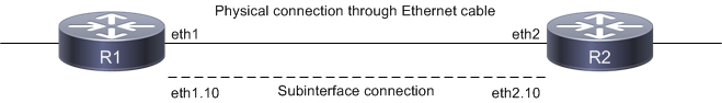
Subinterface connections
The eth1.10 subinterface is created on R1, and eth2.10 is created on R2.
Note: Layer 3 Subinterfaces can be created on physical and LAG interfaces.
Creating a Subinterface
#configure terminal | Enter configure mode. |
(config)#interface eth1 | Enter interface mode |
(config-if)#interface eth1.10 | Creates a sub-interface as eth1.10 |
(config-if)#encapsulation dot1q 10 | Configure the encapsulation as dot1q matching vlan 10 |
(config-if)#ip address 10.10.10.1/24 | Assigning IP address to sub-interface |
(config-if)#commit | Commit the candidate configuration to the running configuration |
(config-if)#exit | Exit interface mode |
Creating a Subinterface with Encapsulation
Double encapsulation as dot1q
#configure terminal | Configure terminal |
(config)#interface eth1.1010 | Configure subinterface |
(config-if)# encapsulation dot1q 10 inner-dot1q 10 | Configure encapsulation with inner tag |
(config-if)#ip address 192.168.1.50/24 | Configuring ip address |
(config-if)#commit | Commit the candidate configuration to the running configuration |
(config-if)#exit | Exit configure mode |
Double encapsulation as dot1ad
#configure terminal | Configure terminal |
(config)#interface eth1.20 | Configure subinterface |
(config-if)# encapsulation dot1ad 20 inner-dot1q 20 | Configure encapsulation with inner tag |
(config-if)#ip address 192.168.2.50/24 | Configuring ip address |
(config-if)#commit | Commit the candidate configuration to the running configuration |
(config-if)#exit | Exit configure mode |
Note: Use dot1ad ethertype (0x8100 | 0x88a8 | 0x9100 | 0x9200)command to configure the service-tpid value on parent port of a subinterface. By this the tpid used for service tag for a subinterface may be inherited from the one applied to parent interface.
Note: For any dot1ad subinterface to be functional, dot1ad ethertype should be set to desired value as 0x88a8/0x9100/0x9200. Default value is 0x8100. To verify the ethertype value for the interface use show interface <subinterface> command.
L3SI Statistics
Enable below commands to get subinterface statistics
#configure terminal | Configure terminal |
(config)#hardware-profile statistics ac-lif enable | Enable hardware profile statistics |
(config)#commit | Commit the candidate configuration to the running configuration |
(config)#exit | Exit configure mode |
Note: Reload the node, and then only statistics command will get effective.
Displaying Subinterfaces
In OcNOS, subinterfaces appear as any physical interface in the show running-coccnfig or the show ip interface brief output and can be configured as any other interface.
The following examples display subinterface information from various show commands.
Note: The below command output is just for reference and is not directly related to the configuration provided above
show interface brief
RTR1#show interface brief
Codes: ETH - Ethernet, LB - Loopback, AGG - Aggregate, MLAG - MLAG Aggregate
FR - Frame Relay, TUN -Tunnel, PBB - PBB Logical Port, VP - Virtual Port
CVP - Channelised Virtual Port, METH - Management Ethernet, UNK- Unknown
ED - ErrDisabled, PD - Protocol Down, AD - Admin Down, PD(Min-links) - Protocol Down Min-links
DV - DDM Violation, NA - Not Applicable
NOM - No operational members, PVID - Port Vlan-id
HD - ESI Hold Timer Down
--------------------------------------------------------------------------------
Ethernet Type PVID Mode Status Reason Speed Port
Interface Ch #
--------------------------------------------------------------------------------
ce49 ETH -- routed up none 100g --
--------------------------------------------------------------------------------
Interface Type Status Reason Speed
--------------------------------------------------------------------------------
ce49.2 SUBINTERFACE up -- 0
ce49.3 SUBINTERFACE up -- 0
ce49.4 SUBINTERFACE up -- 0
ce49.5 SUBINTERFACE up -- 0
ce49.6 SUBINTERFACE up -- 0
show ip interface brief
RTR1#show ip interface brief
'*' - address is assigned by dhcp client
Interface IP-Address Admin-Status Link-Status
ce49 unassigned up up
ce49.2 49.49.2.1 up up
ce49.3 49.49.3.1 up up
ce49.4 49.49.4.1 up up
ce49.5 49.49.5.1 up up
ce49.6 49.49.6.1 up up
show ip ospf neighbor with VRF enabled
RTR1#show ip ospf neighbor
Total number of full neighbors: 2
OSPF process 1 VRF(default):
Neighbor ID Pri State Dead Time Address Interface Instance ID
4.4.4.4 1 Full/DR 00:00:32 48.48.2.2 vlan1.2 0
4.4.4.4 1 Full/DR 00:00:38 48.48.3.2 vlan1.3 0
Total number of full neighbors: 1
OSPF process 2 VRF(CUST-2):
Neighbor ID Pri State Dead Time Address Interface Instance ID
11.11.2.1 1 Full/DR 00:00:39 49.49.2.2 ce49.2 0
Total number of full neighbors: 1
OSPF process 3 VRF(CUST-3):
Neighbor ID Pri State Dead Time Address Interface Instance ID
11.11.3.1 1 Full/Backup 00:00:33 49.49.3.2 ce49.3 0
Total number of full neighbors: 1
OSPF process 4 VRF(CUST-4):
Neighbor ID Pri State Dead Time Address Interface Instance ID
11.11.4.1 1 Full/Backup 00:00:31 49.49.4.2 ce49.4 0
Total number of full neighbors: 1
OSPF process 5 VRF(CUST-5):
Neighbor ID Pri State Dead Time Address Interface Instance ID
11.11.5.1 1 Full/Backup 00:00:39 49.49.5.2 ce49.5 0
show ip route with VRF enabled
RTR1#show ip route
Codes: K - kernel, C - connected, S - static, R - RIP, B - BGP
O - OSPF, IA - OSPF inter area
N1 - OSPF NSSA external type 1, N2 - OSPF NSSA external type 2
E1 - OSPF external type 1, E2 - OSPF external type 2
i - IS-IS, L1 - IS-IS level-1, L2 - IS-IS level-2,
ia - IS-IS inter area, E - EVPN,
v - vrf leaked
* - candidate default
IP Route Table for VRF "default"
C 1.2.200.0/24 is directly connected, xe1.200, 01:29:19
O 4.4.4.4/32 [110/11] via 48.48.3.2, vlan1.3, 00:37:17
[110/11] via 48.48.2.2, vlan1.2
O 44.44.44.0/24 [110/2] via 48.48.3.2, vlan1.3, 00:37:17
[110/2] via 48.48.2.2, vlan1.2
C 47.47.2.0/24 is directly connected, xe47.2, 00:34:42
C 48.48.2.0/24 is directly connected, vlan1.2, 00:41:19
C 48.48.3.0/24 is directly connected, vlan1.3, 00:41:19
C 127.0.0.0/8 is directly connected, lo, 01:30:09
Gateway of last resort is not set
RTR1#show ip route vrf all
Codes: K - kernel, C - connected, S - static, R - RIP, B - BGP
O - OSPF, IA - OSPF inter area
N1 - OSPF NSSA external type 1, N2 - OSPF NSSA external type 2
E1 - OSPF external type 1, E2 - OSPF external type 2
i - IS-IS, L1 - IS-IS level-1, L2 - IS-IS level-2,
ia - IS-IS inter area, E - EVPN,
v - vrf leaked
* - candidate default
IP Route Table for VRF "default"
C 1.2.200.0/24 is directly connected, xe1.200, 01:29:32
O 4.4.4.4/32 [110/11] via 48.48.3.2, vlan1.3, 00:37:30
[110/11] via 48.48.2.2, vlan1.2
O 44.44.44.0/24 [110/2] via 48.48.3.2, vlan1.3, 00:37:30
[110/2] via 48.48.2.2, vlan1.2
C 47.47.2.0/24 is directly connected, xe47.2, 00:34:55
C 48.48.2.0/24 is directly connected, vlan1.2, 00:41:32
C 48.48.3.0/24 is directly connected, vlan1.3, 00:41:32
C 127.0.0.0/8 is directly connected, lo, 01:30:22
IP Route Table for VRF "management"
C 127.0.0.0/8 is directly connected, lo.management, 01:30:22
C 192.168.10.0/24 is directly connected, eth0, 01:30:22
IP Route Table for VRF "CUST-1"
C 127.0.0.0/8 is directly connected, lo.CUST-1, 01:30:22
IP Route Table for VRF "CUST-2"
C 1.1.2.0/24 is directly connected, xe1.2, 01:29:35
C 1.2.101.0/24 is directly connected, xe1.101, 01:29:34
C 1.3.201.0/24 is directly connected, xe1.201, 01:29:32
O 11.11.2.0/24 [110/20] via 49.49.2.2, ce49.2, 00:51:06
O 11.12.101.0/24 [110/20] via 49.49.2.2, ce49.2, 00:51:06
O 11.13.201.0/24 [110/20] via 49.49.2.2, ce49.2, 00:51:06
C 49.49.2.0/24 is directly connected, ce49.2, 01:29:31
C 127.0.0.0/8 is directly connected, lo.CUST-2, 01:30:22
IP Route Table for VRF "CUST-3"
C 1.1.3.0/24 is directly connected, xe1.3, 01:29:35
C 1.2.102.0/24 is directly connected, xe1.102, 01:29:34
C 1.3.202.0/24 is directly connected, xe1.202, 01:29:32
O 11.11.3.0/24 [110/20] via 49.49.3.2, ce49.3, 01:12:44
O 11.12.102.0/24 [110/20] via 49.49.3.2, ce49.3, 01:12:44
O 11.13.202.0/24 [110/20] via 49.49.3.2, ce49.3, 01:12:44
C 49.49.3.0/24 is directly connected, ce49.3, 01:29:31