MPLS Layer-3 VPN Configurations
This chapter contains configurations for MPLS Layer-3 Virtual Private Networks (VPNs).
Overview
The MPLS Layer-3 VPN solution provides address space and routing separation via the use of per-VPN Routing and Forwarding tables (VRFs), and MPLS switching in the core and at the edge of the network. VPN customer routing data is imported into the VRFs utilizing the Route Target BGP extended community. This routing data is identified by a Route Distinguisher (RD) and is distributed among Provider Edge (PE) routers using Multi-Protocol BGP extensions.
Terminology
The following illustrates a Virtual Private Network in a CConnect Service Provider Network. This illustration corresponds to the terms defined in this subsection.
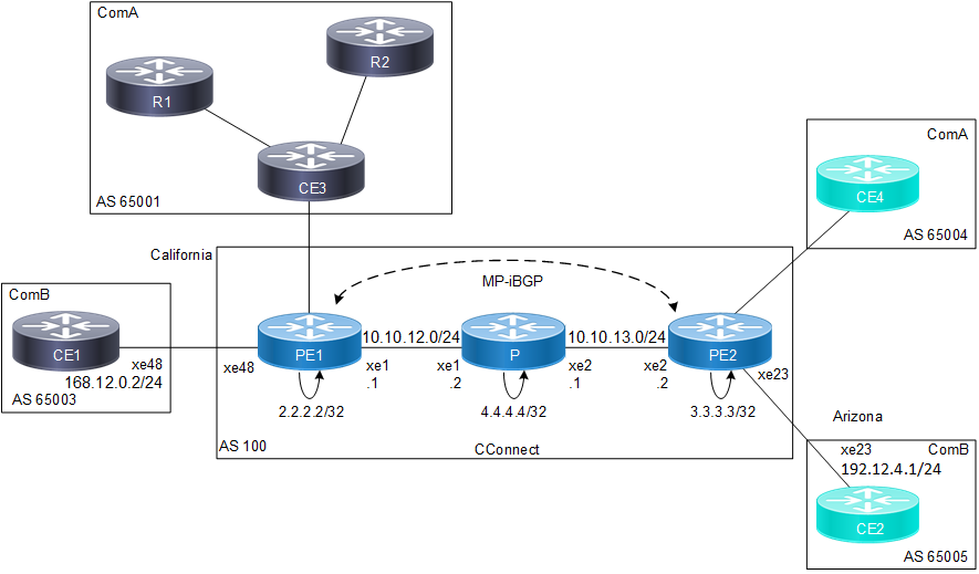
CConnect Provider with ComA and ComB Customers
• Service Provider
The organization that owns the infrastructure that provides leased lines to customers, offering them a Virtual Private Network Service. In the above illustration, CConnect is the service provider providing services to clients ComA and ComB.
• Customer Edge (CE) Router
A router at a customer’s site that connects to the Service Provider via one or more Provider Edge routers. In the above illustration, CE1, CE2, CE3 and CE4 are all CE routers connected directly to the CConnect network.
• Provider Edge (PE) Router
A provider’s router connected to a CE router through a leased line or dial-up connection. In the above illustration, PE1 and PE2 are the PE routers, because they link the CConnect service provider to its clients.
• Provider Core Router (P)
The devices in the core of the service provider network, which are generally not Provider Edge routers. In the above illustration, the P router is the Provider device, not connected to any customer, and is the core of the CConnect network.
• Site
A contiguous part of the customer network. A site connects to the provider network through transmission lines, using a CE and PE router. In the above illustration, R1, R2 and CE3 comprise a Customer network, and are seen as a single site by the CConnect network.
• Customer Router
In the illustration above, R1 and R2 are the Customer routers, and are not directly connected to the CConnect network.
The VPN Routing Process
The OcNOS MPLS-VPN Routing process follows these steps:
1. Service Providers provide VPN services from PE routers that communicate directly with CE routers via an Ethernet Link.
2. Each PE router maintains a Routing and Forwarding table (VRF) for each customer. This guarantees isolation, and allows the usage of uncoordinated private addresses. When a packet is received from the CE, the VRF that is mapped to that site is used to determine the routing for the data. If a PE has multiple connections to the same site, a single VRF is mapped to all of those connections.
3. After the PE router learns of the IP prefix, it converts it into a VPN-IPv4 prefix by prepending it with an 8-byte Route Distinguisher (RD). The RD ensures that even if two customers have the same address, two separate routes to that address can be maintained. These VPN-IPv4 addresses are exchanged between the PE routers through MP-BGP.
4. A unique Router ID (usually the loopback address) is used to allocate a label, and enable VPN packet forwarding across the backbone.
5. Based on routing information stored in the VRF table, packets are forwarded to their destination using MPLS. Each PE router allocates a unique label to every route in each VRF (even if they have the same next hop), and propagates these labels, together with 12-byte VPN-IPv4 addresses, through Multi-Protocol BGP.
6. Ingress PE routers prepend a two-level label stack to the VPN packet, which is forwarded across the Provider network. This label stack contains a BGP-specific label from the VRF table (associated with the incoming interface), specifying the BGP next hop and an LDP-specific label from the global FTN table, specifying the IP next hop.
7. The Provider router in the network switches the VPN packet, based on the top label or the LDP-specific label in the stack. This top label is used as the key to lookup in the incoming interface’s Incoming Labels Mapping table (ILM). If there is an outbound label, the label is swapped, and the packet is forwarded to the next hop; if not, the router is the penultimate router, and it pops the LDP-specific label, and forwards the packet with only the BGP-specific label to the egress PE router.
8. The egress PE router pops the BGP-specific label, performs a single label lookup in the outbound interface, and sends the packet to the appropriate CE router.
Configure MPLS Layer-3 VPN
The MPLS Layer-3 VPN configuration process can be divided into the following tasks
1. Establish connection between PE routers.
2. Configure PE1 and PE2 as iBGP neighbors.
3. Create VRF.
4. Associate interfaces to VRFs.
5. Configure VRF Route Destination and Route Targets.
6. Configure CE neighbor for the VPN.
7. Verify the MPLS to VPN configuration.
Topology
In this example, the CConnect MPLS-VPN backbone has two customers — ComA and ComB. Both customers have sites in California and Arizona. The following topology shows BGP4 address assignment between PE and CE routers. The steps that follow provision a customer VPN service across the MPLS-VPN backbone.
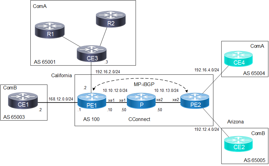
Connect Sample Topology
To establish this connection involves three steps:
Enable Label Switching
This is a sample configuration to enable label switching for the Labeled Switched Path (LSP) between PE1 and PE2 (refer to Figure 3-4).
Enable Label Switching: PE1
configure terminal | Enter configure mode |
(config)#interface lo | Enter interface mode |
(config-if)#ip address 2.2.2.2/32 secondary | Assign the IPv4 address |
(config-if)#exit | Exit interface mode |
(config)#interface xe1 | Enter Interface mode |
(config-if)#ip address 10.10.12.1/24 | Assign IPv4 address |
(config-if)#label-switching | Enabling label switching capability on router |
(config-if)#commit | Commit the transaction. |
Enable Label Switching: P
configure terminal | Enter configure mode |
(config)#interface lo | Enter interface mode |
(config-if)#ip address 4.4.4.4/32 secondary | Assign the IPv4 address |
(config-if)#exit | Exit interface mode |
(config)#interface xe1 | Enter Interface mode |
(config-if)#ip address 10.10.12.2/24 | Assign IPv4 address |
(config-if)#label-switching | Enabling label switching capability on router |
(config-if)#commit | Commit the transaction. |
(config)#interface xe2 | Enter Interface mode |
(config-if)#ip address 10.10.13.1/24 | Assign IPv4 address |
(config-if)#label-switching | Enabling label switching capability on router |
(config-if)#commit | Commit the transaction. |
Enable Label Switching: PE2
configure terminal | Enter configure mode |
(config)#interface lo | Enter interface mode |
(config-if)#ip address 3.3.3.3/32 secondary | Assign the IPv4 address |
(config-if)#exit | Exit interface mode |
(config)#interface xe2 | Enter Interface mode |
(config-if)#ip address 10.10.13.2/24 | Assign IPv4 address |
(config-if)#label-switching | Enabling label switching capability on router |
(config-if)#commit | Commit the transaction. |
Enable IGP
What follows is a sample configuration to establish connections between the two Provider Edge routers PE1 and PE2.
Enable IGP Switching: PE1
configure terminal | Enter configure mode |
(config)#router ospf 100 | Configure the routing process and specify the Process ID (100) |
(config-router)#network 10.10.12.0/24 area 0 | Define the interface on which OSPF runs and associate the area ID (0) with the interface |
(config-router)#network 2.2.2.2/32 area 0 | Define the interface on which OSPF runs and associate the area ID (0) with the interface |
(config-router)#commit | Commit the transaction. |
Enable IGP Switching: P
configure terminal | Enter configure mode |
(config)#router ospf 100 | Configure the routing process and specify the Process ID (100) |
(config-router)#network 10.10.12.0/24 area 0 | Define the interface on which OSPF runs and associate the area ID (0) with the interface |
(config-router)#network 10.10.13.0/24 area 0 | Define the interface on which OSPF runs and associate the area ID (0) with the interface |
(config-router)#network 4.4.4.4/32 area 0 | Define the interface on which OSPF runs and associate the area ID (0) with the interface |
(config-router)#commit | Commit the transaction. |
Enable IGP Switching: PE2
configure terminal | Enter configure mode |
(config)#router ospf 100 | Configure the routing process and specify the Process ID (100) |
(config-router)#network 3.3.3.3/32 area 0 | Define the interface on which OSPF runs and associate the area ID (0) with the interface |
(config-router)#commit | Commit the transaction. |
Enable Label Switching Protocol
Label switching protocols are used to set up a Label-Switched Path (LSP) between PE routers. OcNOS supports LDP and RSVP-TE protocols for label switching. Enable either LDP or RSVP-TE.
This is a sample configuration to enable LDP on the whole path between PE1 and PE2 (see Figure 3-4).
LDP: PE1
configure terminal | Enter configure mode |
(config)#router ldp | Enter router mode for LDP |
(config-router)#exit | Exit router mode |
(config)#interface xe1 | Enter interface mode |
(config-if)#enable-ldp ipv4 | Enabling LDP on interface |
(config-if)#commit | Commit the transaction. |
LDP: P
configure terminal | Enter configure mode |
(config)#router ldp | Enter router mode for LDP |
(config-router)#exit | Exit router mode |
(config)#interface xe1 | Enter interface mode |
(config-if)#enable-ldp ipv4 | Enabling LDP on interface |
(config-if)#exit | Exit interface mode |
(config)#interface xe2 | Enter interface mode |
(config-if)#enable-ldp ipv4 | Enabling LDP on interface |
(config-if)#commit | Commit the transaction. |
LDP: PE2
configure terminal | Enter configure mode |
(config)#router ldp | Enter router mode for LDP |
(config-router)#exit | Exit router mode |
(config)#interface xe2 | Enter interface mode |
(config-if)#enable-ldp ipv4 | Enabling LDP on interface |
(config-if)#commit | Commit the transaction. |
This is a sample configuration to enable RSVP-TE along the entire path between PE1 and PE2 (see Figure 3-4).
RSVP-TE: PE1
configure terminal | Enter configure mode |
(config)#router rsvp | Enter Configure Router mode |
(config-router)#rsvp-path p1 mpls | Enter the path mode for RSVP P1. |
(config-path)#10.10.12.2 loose | Configure loose path |
(config-path)#exit | Exit Configure Router mode |
(config)#rsvp-trunk t1 | Configure RSVP trunk t1 |
(config-rsvp)#primary path p1 | Specify an RSVP path to be used |
(config-rsvp)#from 2.2.2.2 | Assign the source loopback address to the RSVP trunk |
(config-rsvp)#to 3.3.3.3 | Assign the source loopback address to the to the RSVP trunk |
(config-rsvp)#exit | Exit RSVP trunk mode |
(config)#interface xe1 | Enter the interface mode |
(config-if)#enable-rsvp | Enable RSVP in interface |
(config-if)#commit | Commit the transaction. |
RSVP-TE: P
configure terminal | Enter configure mode |
(config)#router rsvp | Enter Configure Router mode |
(config-router)#exit | Exit Configure Router mode |
(config)#interface xe1 | Enter the interface mode |
(config-if)#enable-rsvp | Enable RSVP in interface |
(config-if)#exit | Exit interface mode |
(config)#interface xe2 | Enter the interface mode |
(config-if)#enable-rsvp | Enable RSVP in interface |
(config-if)#commit | Commit the transaction. |
RSVP-TE: PE2
configure terminal | Enter configure mode |
(config)#router rsvp | Enter Configure Router mode |
(config-router)#rsvp-trunk t1 | Configure RSVP trunk t1 |
(config-rsvp)#from 3.3.3.3 | Assign the source loopback address to the RSVP trunk |
(config-rsvp)#to 2.2.2.2 | Assign the source loopback address to the to the RSVP trunk |
(config-rsvp)#exit | Exit RSVP trunk mode |
(config)#interface xe2 | Enter the interface mode |
(config-if)#enable-rsvp | Enable RSVP in interface |
(config-if)#commit | Commit the transaction. |
Configure PEs as BGP Neighbors
BGP is the preferred protocol to transport VPN routes because of its multiprotocol capability and its scalability. Its ability to exchange information between indirectly connected routers supports keeping VPN routing information out of the Provider (P) routers. The P routers carry information as an optional BGP attribute. Additional attributes are transparently forwarded by any P router. The MPLS-VPN forwarding model does not require the P routers to make routing decisions based on VPN addresses: They forward packets based on the label value attached to the packet. The P routers do not require a VPN configuration in order to carry this information.
PE1
#configure terminal | Enter the configure terminal |
(config)#router bgp 100 | Enter the Router BGP mode, ASN: 100 |
(config-router)#bgp router-id 2.2.2.2 | Router identifier for BGP |
(config-router)#exit | Exit router BGP mode |
(config)#router ldp | Enter the Router LDP mode |
(config-router)#exit | Exit the Router LDP mode |
(config)#router bgp 100 | Enter the Router BGP mode, ASN: 100 |
(config-router)#neighbor 3.3.3.3 remote-as 100 | Configuring ABR1 as iBGP neighbor using it's loopback IP |
(config-router)#neighbor 3.3.3.3 update-source 2.2.2.2 | Source of routing updates |
(config-router)#address-family vpnv4 unicast | Configure VPNv4 address family |
(config-router-af)#neighbor 3.3.3.3 activate | Activate the VPN neighbor |
(config-router-af)exit-address-family | Exit address family mode |
(config-router)#address-family ipv4 unicast | Configure IPv4 address family |
(config-router-af)#neighbor 3.3.3.3 activate | Activate the IPv4 neighbor |
(config-router-af)#commit | Commit the transaction. |
PE2
#configure terminal | Enter the configure terminal |
(config)#router bgp 100 | Enter the Router BGP mode, ASN: 100 |
(config-router)#bgp router-id 3.3.3.3 | Router identifier for BGP |
(config-router)#exit | Exit router BGP mode |
(config)#router ldp | Enter the Router LDP mode |
(config-router)#exit | Exit the Router LDP mode |
(config)#router bgp 100 | Enter the Router BGP mode, ASN: 100 |
(config-router)#neighbor 2.2.2.2 remote-as 100 | Configuring ABR1 as iBGP neighbor using it's loopback IP |
(config-router)#neighbor 2.2.2.2 update-source 3.3.3.3 | Source of routing updates |
(config-router)#address-family vpnv4 unicast | Configure VPNv4 address family |
(config-router-af)#neighbor 2.2.2.2 activate | Activate the VPN neighbor |
(config-router-af)exit-address-family | Exit address family mode |
(config-router)#address-family ipv4 unicast | Configure IPv4 address family |
(config-router-af)#neighbor 2.2.2.2 activate | Activate the IPv4 neighbor |
(config-router-af)#commit | Commit the transaction. |
Create VRF
Each PE router in the MPLS-VPN backbone is attached to a site that receives routes from a specific VPN, so the PE router must have the relevant Virtual Routing and Forwarding (VRF) configuration for that VPN.
This command creates a VRF RIB (Routing Information Base), assigns a VRF-ID, and switches the command mode to vrf mode. The following example creates a VRF named ComB.
PE1
#configure terminal | Enter the configure terminal |
(config)#ip vrf ComB | Configure VRF instance |
(config-vrf)#rd 2:1 | Configure Router Distinguisher value |
(config-vrf)#exit | Exit VRF mode |
(config)#ip vrf ComA | Configure VRF instance |
(config-vrf)#rd 1:2 | Configure Router Distinguisher value |
(config-vrf)#exit | Exit VRF mode |
(config)#commit | Commit the transaction. |
PE2
#configure terminal | Enter the configure terminal |
(config)#ip vrf ComB | Configure VRF instance |
(config-vrf)#rd 1:2 | Configure Router Distinguisher value |
(config-vrf)#exit | Exit VRF mode |
(config)#ip vrf ComA | Configure VRF instance |
(config-vrf)#rd 2:1 | Configure Router Distinguisher value |
(config-vrf)#exit | Exit VRF mode |
(config)#commit | Commit the transaction. |
Associate Interfaces to VRFs
After the VRFs are defined on the PE router, the PE router needs to recognize which interfaces belong to which VRF. The VRF is populated with routes from connected sites. More than one interface can belong to the same VRF.
In the following example, interface xe48 is associated with the VRF named ComB.
PE1
#configure terminal | Enter the configure terminal |
(config)#interface xe49 | Enter interface mode |
(config-if)#ip vrf forwarding ComA | Bind the VRF instance to the interface |
(config-if)#ip address 192.16.2.2/24 | Assign IPv4 address |
(config-if)exit | Exit interface mode |
(config)#interface xe48 | Enter interface mode |
(config-if)#ip vrf forwarding ComB | Bind the VRF instance to the interface |
(config-if)#ip address 168.12.0.3/24 | Assign IPv4 address |
(config-if)exit | Exit interface mode |
PE2
#configure terminal | Enter the configure terminal |
(config)#interface xe48 | Enter interface mode |
(config-if)#ip vrf forwarding ComA | Bind the VRF instance to the interface |
(config-if)#ip address 192.16.4.2/24 | Assign IPv4 address |
(config-if)exit | Exit interface mode |
(config)#interface xe49 | Enter interface mode |
(config-if)#ip vrf forwarding ComB | Bind the VRF instance to the interface |
(config-if)#ip address 168.12.4.2/24 | Assign IPv4 address |
(config-if)exit | Exit interface mode |
(config)#commit | Commit the transaction. |
Configure VRF—RD and Route Targets
After the VRF is created, configure Router Distinguishers and the Route Targets.
Configure Route Distinguishers
Route Distinguishers (RDs) make all customer routes unique. The routes must be unique, so that Multi-Protocol BGP treats the same prefix from two different VPNs as non-comparable routes. To configure RDs, a sequence of 64 bits is prepended to the IPv4 address in the Multi-Protocol BGP update. BGP considers two IPv4 addresses with different RDs as non-comparable, even if they have the same address and mask.
Assign a particular value to the RD for each VRF on the PE router. To display the routing table for a VRF, use the show ip route vrf command.
The following example shows adding an RD. Configure a VRF in both PEs with a unique RD value:
PE1
#configure terminal | Enter the configure terminal |
(config)#ip vrf ComA | Configure VRF instance |
(config-vrf)#rd 2:2 | Configure Router Distinguisher value |
(config-vrf)#route-target both 200:1 | Configure route-target as both |
(config-vrf)#exit | Exit VRF mode |
(config)#ip vrf ComB | Configure VRF instance |
(config-vrf)#rd 1:1 | Configure Router Distinguisher value |
(config-vrf)#route-target both 100:1 | Configure route-target as both |
(config-vrf)#exit | Exit VRF mode |
(config)#commit | Commit the transaction. |
PE2
#configure terminal | Enter the configure terminal |
(config)#ip vrf ComA | Configure VRF instance |
(config-vrf)#rd 2:1 | Configure Router Distinguisher value |
(config-vrf)#route-target both 200:1 | Configure route-target as both |
(config-vrf)#exit | Exit VRF mode |
(config)#ip vrf ComB | Configure VRF instance |
(config-vrf)#rd 1:2 | Configure Router Distinguisher value |
(config-vrf)#route-target both 100:1 | Configure route-target as both |
(config-vrf)#exit | Exit VRF mode |
(config)#commit | Commit the transaction. |
Configure Route Targets
Any routes learned from customers are advertised across the network through Multi-Protocol BGP, and any routes learned through Multi-Protocol BGP are added into the appropriate VRFs. The route target helps PE routers identify which VRFs should receive the routes.
The route-target command creates lists of import and export route-target extended communities for the VRF. It specifies a target VPN extended community. Execute the command once for each community. All routes with the specific route-target extended community are imported into all VRFs with the same extended community as an import route-target.
The following example demonstrates the route-target configuration.
PE1
#configure terminal | Enter the configure terminal |
(config)#ip vrf ComA | Configure VRF instance |
(config-vrf)#rd 2:2 | Configure Router Distinguisher value |
(config-vrf)#route-target both 200:1 | Configure route-target as both |
(config-vrf)#exit | Exit VRF mode |
(config)#ip vrf ComB | Configure VRF instance |
(config-vrf)#rd 1:1 | Configure Router Distinguisher value |
(config-vrf)#route-target both 100:1 | Configure route-target as both |
(config-vrf)#exit | Exit VRF mode |
(config)#commit | Commit the transaction. |
PE2
#configure terminal | Enter the configure terminal |
(config)#ip vrf ComA | Configure VRF instance |
(config-vrf)#rd 2:1 | Configure Router Distinguisher value |
(config-vrf)#route-target both 200:1 | Configure route-target as both |
(config-vrf)#exit | Exit VRF mode |
(config)#ip vrf ComB | Configure VRF instance |
(config-vrf)#rd 1:2 | Configure Router Distinguisher value |
(config-vrf)#route-target both 100:1 | Configure route-target as both |
(config-vrf)#exit | Exit VRF mode |
(config)#commit | Commit the transaction. |
Configure CE Neighbor for the VPN (Using BGP/ OSPF)
To provide a VPN service, the PE-router must be configured so that any routing information learned from a VPN customer interface can be associated with a particular VRF. This is achieved using any standard routing protocol process (OSPF, BGP or static routes etc). Use any one of the following configurations (BGP, or OSPF) to configure the CE neighbor.
Using BGP
The BGP sessions between PE and CE routers can carry different types of routes (VPN-IPv4, IPv4 routes). Address families are used to control the type of BGP session. Configure a BGP address family for each VRF on the PE-router, and a separate address family to carry VPN-IPv4 routes between PE routers. All non-VPN BGP neighbors are defined using the IPv4 address mode. Each VPN BGP neighbor is defined under its associated address family mode.
A separate address family entry is used for every VRF, and each address family entry can have multiple CE routers within the VRF.
The PE and CE routers must be directly connected for BGP4 sessions; BGP multihop is not supported between PE and CE routers.
The following example places the router in address family mode, and specifies company names, ComA and ComB, as the names of the VRF instance to associate with subsequent IPv4 address family configuration mode commands. This configuration is used when BGP is used for PE and CE.
PE1
configure terminal | Enter configure mode |
(config)#router bgp 100 | Enter BGP router mode |
(config-router)#address-family ipv4 unicast | Enter address family mode |
(config-router-af)#redistribute connected | Redistribute connected addresses |
(config-router-af)#exit-address-family | Exit address family mode |
(config-router)#address-family ipv4 vrf ComA | Enter the IPv4 address family for VRF comA |
(config-router)#neighbor 192.16.2.3 remote-as 65001 | Specify the neighbor |
(config-router-af)#neighbor 192.16.2.3 activate | Activate the neighbor |
(config-router-af)#exit-address-family | Exit address family mode |
(config-router)#address-family ipv4 vrf ComB | Enter the IPv4 address family for VRF comA |
(config-router)#neighbor 168.12.0.2 remote-as 65003 | Specify the neighbor |
(config-router-af)#neighbor 192.12.0.2 activate | Activate the neighbor |
(config-router-af)#exit-address-family | Exit address family mode |
(config-router)#commit | Commit the transaction |
PE2
configure terminal | Enter configure mode |
(config)#router bgp 100 | Enter BGP router mode |
(config-router)#address-family ipv4 unicast | Enter address family mode |
(config-router-af)#redistribute connected | Redistribute connected addresses |
(config-router-af)#exit-address-family | Exit address family mode |
(config-router)#address-family ipv4 vrf ComA | Enter the IPv4 address family for VRF comA |
(config-router)#neighbor 192.16.4.3 remote-as 65004 | Specify the neighbor |
(config-router-af)#neighbor 192.16.4.3 activate | Activate the neighbor |
(config-router-af)#exit-address-family | Exit address family mode |
(config-router)#address-family ipv4 vrf ComB | Enter the IPv4 address family for VRF comA |
(config-router)#neighbor 168.12.4.1 remote-as 65005 | Specify the neighbor |
(config-router-af)#neighbor 192.12.4.1 activate | Activate the neighbor |
(config-router-af)#exit-address-family | Exit address family mode |
(config-router)#commit | Commit the transaction |
CE1: BGP
configure terminal | Enter configure mode |
(config)#interface xe48 | Enter interface mode for xe48 |
(config-if)#ip address 168.12.0.2/24 | Assign IP address |
(config-if)#exit | Exit interface mode |
(config)#router bgp 65003 | Enter BGP router mode |
(config-router)#neighbor 168.12.0.3 remote-as 100 | Specify the neighbor |
(config-router)#address-family ipv4 unicast | Enter address family mode |
(config-router-af)#neighbor 168.12.0.3 activate | Activate the neighbor |
(config-router-af)#redistribute connected | Redistribute connected addresses |
(config-router-af)#commit | Commit the transaction |
CE2: BGP
configure terminal | Enter configure mode |
(config)#interface xe23 | Enter interface mode for xe48 |
(config-if)#ip address 192.12.4.1/24 | Assign IP address |
(config-if)#exit | Exit interface mode |
(config)#router bgp 65005 | Enter BGP router mode |
(config-router)#neighbor 192.12.4.2 remote-as 100 | Specify the neightbor |
(config-router)#address-family ipv4 unicast | Enter address family mode |
(config-router-af)#neighbor 192.12.4.2 activate | Activate the neighbor |
(config-router-af)#redistribute connected | Redistribute connected addresses |
(config-router-af)#commit | Commit the transaction |
Using OSPF
Unlike BGP, OSPF does not run different routing contexts within one process. Thus, for running OSPF between the PE and CE routers, configure a separate OSPF process for each VRF that receives VPN routes through OSPF. The PE router distinguishes routers belonging to a specific VRF, by associating a particular customer interface to a specific VRF and to a particular OSPF process.
To redistribute VRF OSPF routes into BGP, redistribute OSPF under the BGP VRF address family submode.
PE1
configure terminal | Enter configure mode |
(config)#router ospf 101 comA | Enter OSPF router mode |
(config-router)#network 192.16.3.0/24 area 0 | Define the network on which OSPF runs and associate area ID |
(config-router)#redistribute bgp | Redistribute BGP |
(config-router)#exit | Exit router mode |
(config)#router ospf 102 comB | Enter OSPF router mode |
(config-router)#network 168.12.0.2/24 area 0 | Define the network on which OSPF runs and associate area ID |
(config-router)#redistribute bgp | Redistribute BGP |
(config-router)#commit | Commit the transaction |
(config-router)#exit | Exit router mode |
(config)#router bgp 100 | Enter the Router BGP mode, ASN: 100 |
(config-router)#address-family ipv4 vrf ComA | Configure VRF address family |
(config-router-af)#redistribute ospf | Redistribute OSPF |
(config-router-af)#exit-address-family | Exit address family mode |
(config-router)#address-family ipv4 vrf ComB | Configure VRF address family |
(config-router-af)#redistribute ospf | Redistribute OSPF |
(config-router-af)#redistribute rip | Redistribute RIP |
(config-router-af)#commit | Commit the transaction |
PE2
configure terminal | Enter configure mode |
(config)#router ospf 101 comA | Enter OSPF router mode |
(config-router)#network 192.16.4.0/24 area 0 | Define the network on which OSPF runs and associate area ID |
(config-router)#redistribute bgp | Redistribute BGP |
(config-router)#exit | Exit router mode |
(config)#router ospf 102 comB | Enter OSPF router mode |
(config-router)#network 168.12.0.3/24 area 0 | Define the network on which OSPF runs and associate area ID |
(config-router)#redistribute bgp | Redistribute BGP |
(config-router)#commit | Commit the transaction |
(config-router)#exit | Exit router mode |
(config)#router bgp 100 | Enter the Router BGP mode, ASN: 100 |
(config-router)#address-family ipv4 vrf ComA | Configure VRF address family |
(config-router-af)#redistribute ospf | Redistribute OSPF |
(config-router-af)#exit-address-family | Exit address family mode |
(config-router)#address-family ipv4 vrf ComB | Configure VRF address family |
(config-router-af)#redistribute ospf | Redistribute OSPF |
(config-router-af)#redistribute rip | Redistribute RIP |
(config-router-af)#commit | Commit the transaction |
Verify the MPLS-VPN Configuration
Use the show ip bgp neighbor command to validate the neighbor session between the CE and the PE routers. Use the show ip bgp vpnv4 all command to display all the VRFs and the routes associated with them. The following is sample output for the above commands for the PE1, CE1 and PE2 routers (based on the topology in Figure 3-4).
PE1#show ip bgp neighbors
BGP neighbor is 3.3.3.3, remote AS 100, local AS 100, internal link
BGP version 4, local router ID 2.2.2.2, remote router ID 3.3.3.3
BGP state = Established, up for 00:05:09
Last read 00:00:13, hold time is 90, keepalive interval is 30 seconds
Neighbor capabilities:
Route refresh: advertised and received (old and new)
Address family IPv4 Unicast: advertised and received
Address family VPNv4 Unicast: advertised and received
Received 194 messages, 2 notifications, 0 in queue
Sent 198 messages, 3 notifications, 0 in queue
Route refresh request: received 2, sent 1
Minimum time between advertisement runs is 5 seconds
Update source is 2.2.2.2
For address family: IPv4 Unicast
BGP table version 8, neighbor version 8
Index 1, Offset 0, Mask 0x2
Community attribute sent to this neighbor (both)
3 accepted prefixes
3 announced prefixes
For address family: VPNv4 Unicast
BGP table version 1, neighbor version 1
Index 1, Offset 0, Mask 0x2
Community attribute sent to this neighbor (both)
0 accepted prefixes
2 announced prefixes
Connections established 5; dropped 4
Local host: 2.2.2.2, Local port: 35983
Foreign host: 3.3.3.3, Foreign port: 179
Nexthop: 2.2.2.2
Nexthop global: ::
Nexthop local: ::
BGP connection: non shared network
Last Reset: 00:05:14, due to BGP Notification received
Notification Error Message: (Cease/Other Configuration Change.)
BGP neighbor is 168.12.0.2, vrf ComB, remote AS 65003, local AS 100, external link
BGP version 4, local router ID 168.12.0.3, remote router ID 10.12.65.206
BGP state = Established, up for 00:34:38
Last read 00:00:14, hold time is 90, keepalive interval is 30 seconds
Neighbor capabilities:
Route refresh: advertised and received (old and new)
Address family IPv4 Unicast: advertised and received
Received 85 messages, 0 notifications, 0 in queue
Sent 86 messages, 0 notifications, 0 in queue
Route refresh request: received 0, sent 0
Minimum time between advertisement runs is 30 seconds
For address family: IPv4 Unicast
BGP table version 1, neighbor version 1
Index 1, Offset 0, Mask 0x2
Community attribute sent to this neighbor (standard)
2 accepted prefixes
0 announced prefixes
Connections established 1; dropped 0
Local host: 168.12.0.3, Local port: 179
Foreign host: 168.12.0.2, Foreign port: 36580
Nexthop: 168.12.0.3
Nexthop global: ::
Nexthop local: ::
BGP connection: non shared network
CE1#show ip bgp neighbors
BGP neighbor is 168.12.0.3, remote AS 100, local AS 65003, external link
BGP version 4, local router ID 10.12.65.206, remote router ID 168.12.0.3
BGP state = Established, up for 00:36:14
Last read 00:00:10, hold time is 90, keepalive interval is 30 seconds
Neighbor capabilities:
Route refresh: advertised and received (old and new)
Address family IPv4 Unicast: advertised and received
Received 86 messages, 0 notifications, 0 in queue
Sent 89 messages, 0 notifications, 0 in queue
Route refresh request: received 0, sent 0
Minimum time between advertisement runs is 30 seconds
For address family: IPv4 Unicast
BGP table version 1, neighbor version 1
Index 1, Offset 0, Mask 0x2
Community attribute sent to this neighbor (both)
0 accepted prefixes
2 announced prefixes
Connections established 1; dropped 0
Local host: 168.12.0.2, Local port: 36580
Foreign host: 168.12.0.3, Foreign port: 179
Nexthop: 168.12.0.2
Nexthop global: ::
Nexthop local: ::
BGP connection: non shared network
PE1#show ip bgp vpnv4 all
Status codes: s suppressed, d damped, h history, a add-path, * valid, > best, i - internal, l - labeled
S Stale
Origin codes: i - IGP, e - EGP, ? - incomplete
Network Next Hop Metric LocPrf Weight Path
Route Distinguisher: 1:1 (Default for VRF ComB)
*> l 168.12.0.0/24 0.0.0.0 1 100 32768 ?
168.12.0.2 0 100 0 65003 ?
*>i 192.12.4.0 3.3.3.3 0 100 0 65005 ?
Announced routes count = 2
Accepted routes count = 1
Route Distinguisher: 1:2
*>i 192.12.4.0 3.3.3.3 0 100 0 65005 ?
Announced routes count = 0
Accepted routes count = 1
Route Distinguisher: 2:2 (Default for VRF ComA)
*> l 192.16.2.0 0.0.0.0 1 100 32768 ?
192.16.2.3 0 100 0 65001 ?
Announced routes count = 2
Accepted routes count = 0
PE1#show ip bgp vpnv4 all neighbors 3.3.3.3 routes
For address family: VPNv4 Unicast
Status codes: s suppressed, d damped, h history, a add-path, * valid, > best, i - internal, l - labeled
S Stale
Origin codes: i - IGP, e - EGP, ? - incomplete
Network Next Hop Metric LocPrf Weight Path
Route Distinguisher: 1:2
*>i 192.12.4.0 3.3.3.3 0 100 0 65005 ?
Accepted routes count = 1
PE2#show ip bgp vpnv4 all
Status codes: s suppressed, d damped, h history, * valid, > best, i - internal, l - labeled
S Stale
Origin codes: i - IGP, e - EGP, ? - incomplete
Network Next Hop Metric LocPrf Weight Path
Route Distinguisher: 1:2 (Default for VRF ComB)
*>i 168.12.0.0/24 2.2.2.2 0 100 0 ?
*> l 192.12.4.0 0.0.0.0 0 100 32768 ?
Announced routes count = 1
Accepted routes count = 1
Route Distinguisher: 1:2
*>i 168.12.0.0/24 2.2.2.2 0 100 0 ?
Announced routes count = 0
Accepted routes count = 1
Verify MPLS-L3 VPN VRF Ping and Traceroute
Use the ping mpls l3vpn command for the below requirements:
• PE to PE L3VPN ping via VRF
• PE to remote CE Ping via the VRF
• CE to remote PE ping (to the VRF interface facing its customer edge).
• Trace route from PE to PE via VRF
• Trace route from PE to remote CE via VRF
• Commands for ipv6 ping and trace route
1. PE to PE L3VPN Ping via VRF:
PE2#ping 168.12.0.1 vrf ComB
Press CTRL+C to exit
PING 168.12.0.1 (168.12.0.1) 56(84) bytes of data.
64 bytes from 168.12.0.1: icmp_seq=1 ttl=64 time=0.695 ms
#
2. PE to remote CE Ping via VRF:
PE2#ping 168.12.0.2 vrf ComB
Press CTRL+C to exit
PING 168.12.0.2 (168.12.0.2) 56(84) bytes of data.
64 bytes from 168.12.0.2: icmp_seq=1 ttl=63 time=0.776 ms
--- 168.12.0.2 ping statistics ---
1 packets transmitted, 1 received, 0% packet loss, time 0ms
rtt min/avg/max/mdev = 0.776/0.776/0.776/0.000 ms
PE2#
PE2
3. CE to remote PE ping:
CE1#ping 168.12.0.1
Press CTRL+C to exit
PING 168.12.0.1 (168.12.0.1) 56(84) bytes of data.
64 bytes from 168.12.0.1: icmp_seq=160 ttl=254 time=0.606 ms
64 bytes from 168.12.0.1: icmp_seq=161 ttl=254 time=0.558 ms
64 bytes from 168.12.0.1: icmp_seq=162 ttl=254 time=0.568 ms
64 bytes from 168.12.0.1: icmp_seq=163 ttl=254 time=0.574 ms
64 bytes from 168.12.0.1: icmp_seq=164 ttl=254 time=0.609 ms
--- 168.12.0.2 ping statistics ---
5 packets transmitted, 5 received, 0 errors, 0% packet loss, time 163002ms
4. Trace Route from PE to PE via VRF
PE2#traceroute ip 168.12.0.1 vrf ComB
traceroute to 168.12.0.1 (168.12.0.1), 30 hops max, 60 byte packets
1 168.12.0.1 (168.12.0.1) 0.706 ms 0.743 ms 0.989 ms
5. Trace Route from PE to Remote CE via VRF
PE2#traceroute ip 168.12.0.2 vrf ComB
traceroute to 168.12.0.2 (168.12.0.2), 30 hops max, 60 byte packets
1 168.12.0.1 (168.12.0.1) 0.871 ms 1.006 ms 1.055 ms
2 168.12.0.2 (168.12.0.2) 1.965 ms 2.045 ms 2.256 ms