PIM Sparse Mode Configuration
The Protocol Independent Multicasting-Sparse Mode (PIM-SM) is a multicast routing protocol designed to operate efficiently across Wide Area Networks (WANs) with sparsely distributed groups. It helps geographically dispersed network nodes to conserve bandwidth and reduce traffic by simultaneously delivering a single stream of information to multiple locations. PIM-SM uses the IP multicast model of receiver-initiated membership, supporting both shared and shortest-path trees, and uses soft-state mechanisms to adapt to changing network conditions. It relies on a topology-gathering protocol to populate a multicast routing table with routes.
Terminology
Following is a brief description of terms and concepts used to describe the PIM-SM protocol:
Rendezvous Point
A Rendezvous Point (RP) router is configured as the root of a non-source-specific distribution tree for a multicast group. Join messages from receivers for a group are sent towards the RP. Data from senders is sent to the RP so that receivers can discover who the senders are, and receive traffic destined for the group.
Multicast Routing Information Base
The Multicast Routing Information Base (MRIB) is a multicast topology table derived from the unicast routing table. In PIM-SM, the MRIB decides where to send Join/Prune messages. It also provides routing metrics for destination addresses. These metrics are used when sending and processing Assert messages.
Reverse Path Forwarding
Reverse Path Forwarding (RPF) is an optimized form of flooding, in which the router accepts a packet from SourceA through Interface IF1, only if IF1 is the interface the router uses to reach SourceA. To determine if the interface is correct, it consults its unicast routing tables. The packet that arrives through interface IF1 is forwarded because the routing table lists this interface as the shortest path. The router's unicast routing table determines the shortest path for the multicast packets. Because a router accepts a packet from only one neighbor, it floods the packet only once, meaning that (assuming point-to-point links) each packet is transmitted over each link, once in each direction.
Tree Information Base
The Tree Information Base (TIB) is a collection of states at a PIM router storing the state of all multicast distribution trees at that router. The TIB is created by receiving Join/Prune messages, Assert messages, and IGMP information from local hosts.
Upstream
Upstream indicates that traffic is going towards the root of the tree. The root of the tree might be either the Source or the RP.
Downstream
Downstream indicates that traffic is going away from the root of the tree. The root of tree might be either the Source or the RP.
Source-Based Trees
In Source-Based Trees, the forwarding paths are based on the shortest unicast path to the source. If the unicast routing metric used is hop counts, the branches of the multicast Source-Based Trees are minimum hop. If the metric used is delay, the branches are minimum delay. A corresponding multicast tree directly connects the source to all receivers for every multicast source. All traffic to the members of an associated group passes along the tree made for their source. Source-Based Trees have two entries with a list of outgoing interfaces -- the source address and the multicast group.
Shared Trees
Shared trees, or RP trees (RPT), rely on a central router called the Rendezvous Point (RP) that receives all traffic from the sources, and forwards that traffic to the receivers. There is a single tree for each multicast group, regardless of the number of sources. Only the routers on the tree know about the group, and information is sent only to interested receivers. With an RP, receivers have a place to join, even if no source exists. The shared tree is unidirectional, and information flows only from the RP to the receivers. If a host other than the RP has to send data on the tree, the data must first be tunneled to the RP, then multicast to the members. This means that even if a receiver is also a source, it can only use the tree to receive packets from the RP, and not to send packets to the RP (unless the source is located between the RP and the receivers).
Note: Not all hosts are receivers.
Bootstrap Router
When a new multicast sender starts sending data packets, or a new receiver starts sending Join messages towards the RP for that multicast group, the sender needs to know the next-hop router towards the RP. The bootstrap router (BSR) provides group-to-RP mapping information to all the PIM routers in a domain, allowing them to map to the correct RP address.
Data Flow from Source to Receivers in PIM-SM Network Domain
1. Sending out Hello Messages
PIM routers periodically send Hello messages to discover neighboring PIM routers. Hello messages are multicast using the address, 224.0.0.13 (ALL-PIM-ROUTERS group). Routers do not send any acknowledgement that a Hello message was received. A holdtime value determines the length of time for which the information is valid. In PIM-SM, a downstream receiver must join a group before traffic is forwarded on the interface.
2. Electing a Designated Router
In a multi-access network with multiple routers connected, one of the routers is selected to act as a designated router (DR) for a given period. The DR is responsible for sending Join/Prune messages to the RP for local members.
3. Determining the Rendezvous Point
PIM-SM uses a BSR to originate bootstrap messages, and to disseminate RP information. The messages are multicast to the group on each link. If the BSR is not apparent, the routers flood the domain with advertisements. The router with the highest priority (if priorities are same, the higher IP address applies) is selected to be the RP. Routers receive and store bootstrap messages originated by the BSR. When a DR gets a membership indication from IGMP for (or a data packet from) a directly connected host, for a group for which it has no entry, the designated router (DR) maps the group address to one of the candidate RPs that can service that group. The DR then sends a Join/Prune message towards that RP. In a small domain, the RP can also be configured statically.
4. Joining the Shared Tree
To join a multicast group, a host sends an IGMP message to its upstream router, after which the router can accept multicast traffic for that group. The router sends a Join message to its upstream PIM neighbor in the direction of the RP. When a router receives a Join message from a downstream router, it checks to see if a state exists for the group in its multicast routing table. If a state already exists, the Join message has reached the shared tree, and the interface from which the message was received is entered in the Outgoing Interface list. If no state exists, an entry is created, the interface is entered in the Outgoing Interface list, and the Join message is again sent towards the RP.
5. Registering with the RP
A DR can begin receiving traffic from a source without having a Source or a Group state for that source. In this case, the DR has no information on how to get multicast traffic to the RP through a tree. When the source DR receives the initial multicast packet, it encapsulates it in a Register message, and unicasts it to the RP for that group. The RP de-encapsulates each Register message, and forwards the extracted data packet to downstream members on the RPT. Once the path is established from the source to the RP, the DR begins sending traffic to the RP as standard IP multicast packets, as well as encapsulated within Register messages. The RP temporarily receives packets twice. When the RP detects the normal multicast packets, it sends a Register-Stop message to the source DR, meaning it should stop sending register packets.
6. Sending Register-Stop Messages
When the RP begins receiving traffic from the source, both as Register messages and as unencapsulated IP packets, it sends a Register-Stop message to the DR. This notifies the DR that the traffic is now being received as standard IP multicast packets on the SPT. When the DR receives this message, it stops encapsulating traffic in Register messages.
7. Pruning the Interface
Routers attached to receivers send Prune messages to the RP to disassociate the source from the RP. When an RP receives a Prune message, it no longer forwards traffic from the source indicated in the Prune message. If all members of a multicast group are pruned, the IGMP state of the DR is deleted, and the interface is removed from the Source and Group lists of the group.
8. Forwarding Multicast Packets
PIM-SM routers forward multicast traffic onto all interfaces that lead to receivers that have explicitly joined a multicast group. Messages are sent to a group address in the local subnetwork, and have a Time to Live (TTL) of one (1). The router performs an RPF check, and forwards the packet. If a downstream router has sent a join to this router or is a member of this group, then traffic that arrives on the correct interface is sent to all outgoing interfaces that lead to downstream receivers.
PIM-SM Configuration
PIM-SM is a soft-state protocol. The required steps to configure PIM-SM are the following:
• Enable IP multicast on each PIM router (see Enabling IP Multicast Routing)
• Enable PIM-SM on the desired interfaces (see Enable IPV6 Multicast Routing)
• Configure the RP statically (see Enable PIM-SM Sub-Interface or dynamically (see Configure Rendezvous Point Dynamically Using Bootstrap Router Method) depending on which method you use)
IPV6 PIM-SM Configuration
PIM-SM is a soft-state protocol. The required steps to configure PIM-SM are the following:
• Enable IPv6 multicast on each PIM router (see Enable IPv6 Multicast Routing)
• Enable IPv6 PIM-SM on the desired interfaces (see Enable IPV6 PIM-SM on an Interface)
• Configure the RP statically (see Configuring Rendezvous Point Statically or dynamically (see Configure Rendezvous Point Dynamically Using Bootstrap Router Method) depending on which method you use).
All multicast group states are dynamically maintained as the result of IGMP Report/Leave and PIM Join/Prune messages.
This section provides the steps to configure the PIM-SM feature. Configuration steps and examples are used for two relevant scenarios.
Topology
The following figure displays the network topology used in these examples.
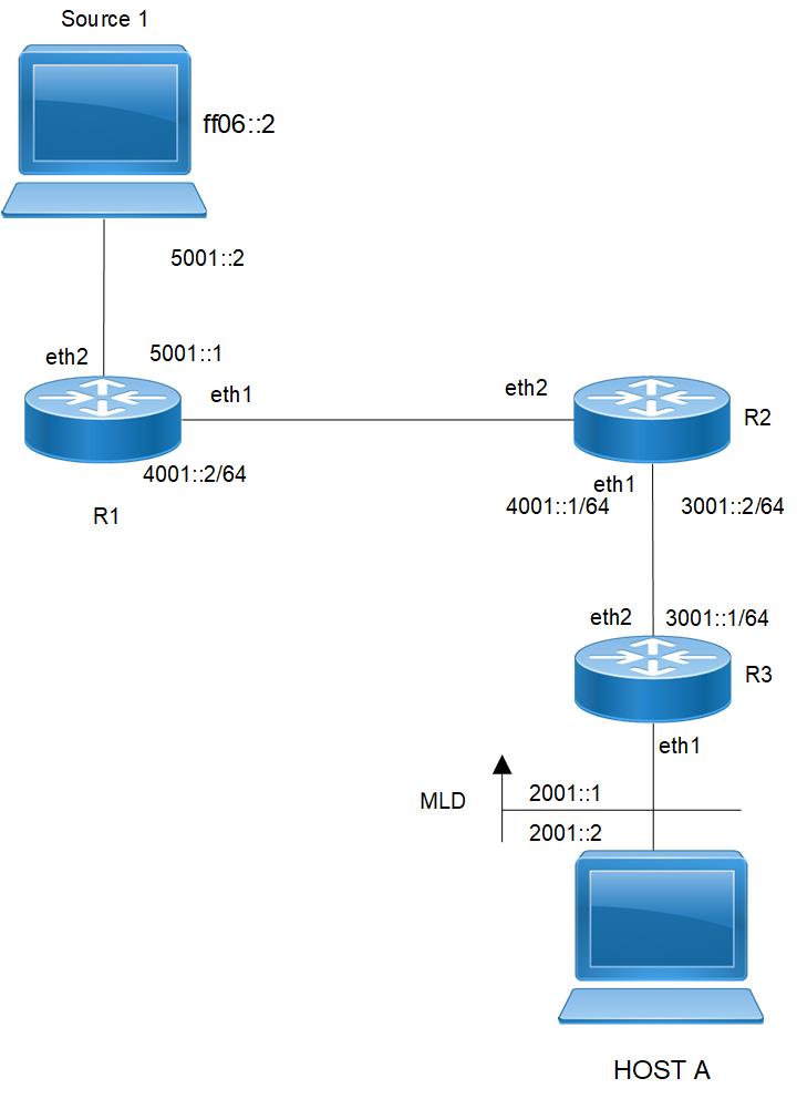
PIM-SM Topology
Enabling IP Multicast Routing
Enable IP multicast routing on all of the PIM routers inside the PIM domain:
Enable IP Multicast Routing
#configure terminal | Enter configure mode. |
(config)#ip multicast-routing | Enable IP multicast routing. |
(config)#commit | Commit the transaction. |
Enable IPV6 Multicast Routing
#configure terminal | Enter configure mode. |
(config)#ipv6 multicast-routing | Enable IPv6 multicast routing. |
(config)#commit | Commit the transaction. |
Enable PIM-SM on an Interface
Enable PIM-SM on all participating interfaces within each of routers inside the PIM domain on which you want to run PIM. In the following sample configuration, both eth1 and eth2 are enabled for PIM-SM on the router.
#configure terminal | Enter configure mode. |
(config)#interface eth1 | Specify the interface (eth1) to be configured and Enter interface mode. |
(config-if)#ip address 10.10.12.11/24 | Configure the IP address for eth1. |
(config-if)#ip pim sparse-mode | Enable PIM sparse mode on the interface. |
(config-if)#exit | Exit the Interface mode. |
(config)#interface eth2 | Configure the IP address for eth2. |
(config-if)#ip address 10.10.13.11/24 | Configure the IP address for eth2. |
(config-if)#ip pim sparse-mode | Enable PIM sparse mode on the interface. |
(config-if)#commit | Commit the transaction. |
(config)#end | End the transaction |
#configure terminal | Enter configure mode. |
(config)#interface eth1 | Specify the interface (eth1) to be configured and Enter interface mode. |
(config-if)#ipv6 address 2001::1/64 | Configure the IPv6 address for eth1. |
(config-if)#ipv6 pim sparse-mode | Enable ipv6 PIM-s, on the interface. |
(config-if)#exit | Exit the Interface mode. |
(config)#interface eth2 | Specify the interface (eth2) to be configured and Enter interface mode. |
(config-if)#ipv6 address 2001::2/64 | Configure the IPv6 address for eth12 |
(config-if)#ip pim sparse-mode | Enable ipv6 PIM-s, on the interface. |
(config-if)#commit | Commit the transaction. |
(config-if)#end | End the session |
Enable PIM-SM Sub-Interface
Enable PIM-SM on all participating interfaces within each of routers inside the PIM domain on which you want to run PIM. In the following sample configuration, both eth1.1 and eth2.1 are enabled for PIM-SM on the router.
#configure terminal | Enter configure mode. |
(config)#interface eth1.1 | Specify the interface (eth1.1) to be configured and Enter interface mode. |
(config-if)#encapsulation dot1q 1 | Configure encapsulation for sub interface |
(config-if)#ip address 10.10.12.11/24 | Configure the IP address for eth1. |
(config-if)#ip pim sparse-mode | Enable PIM sparse mode on the interface. |
(config-if)#exit | Exit the Interface mode. |
(config)#interface eth2.1 | Configure the IP address for eth2.1. |
(config-if)#ip address 10.10.13.11/24 | Configure the IP address for eth2. |
(config-if)#ip pim sparse-mode | Enable PIM sparse mode on the interface. |
(config-if)#encapsulation dot1q 1 | Configure encapsulation for sub interface |
(config-if)#commit | Commit the transaction. |
(config)#end | End the transaction |
#configure terminal | Enter configure mode. |
(config)#interface eth1.1 | Specify the interface (eth1.1) to be configured and Enter interface mode. |
(config-if)#encapsulation dot1q 1 | Configure encapsulation for sub interface |
(config-if)#ipv6 address 2001::1/64 | Configure the IPv6 address for eth1.1 |
(config-if)#ipv6 pim sparse-mode | Enable ipv6 PIM-s, on the interface. |
(config-if)#exit | Exit the Interface mode. |
(config)#interface eth2.1 | Specify the interface (eth2.1) to be configured and Enter interface mode. |
(config-if)#encapsulation dot1q 1 | Configure encapsulation for sub interface |
(config-if)#ipv6 address 2001::2/64 | Configure the IPv6 address for eth2.1 |
(config-if)#ip pim sparse-mode | Enable ipv6 PIM-s, on the interface. |
(config-if)#commit | Commit the transaction. |
(config-if)#end | End the session |
Configuring Rendezvous Point Statically
Every PIM multicast group needs to be associated with the IP address of a Rendezvous Point (RP), which is a router that resides in a multicast network domain. The address of the RP is used as the root of a group-specific distribution tree. All nodes in the domain that want to receive traffic sent to the group are aware of the address of the RP. For all senders to reach all receivers within a group, all routers in the domain must be able to map to the RP address configured for the group. There can be several RPs configured in a network deploying PIM-SM, each serving a different group.
You can statically configure a RP by specifying the RP address with in every router in the PIM domain. The use of statically configured RPs is ideal for small network environments or ones that do not require many RPs and/or require changing the assignment of the RPs often. Changing the assignment of an RP requires the re-configuration of the RP address in all of the routers in the PIM domain.
In static RP configurations, RP failover is not available.
When configuring the RP statically, do the following:
• On every router, include the ip pim rp-address A.B.C.D statement even if a router does not have any source or group member attached to it
• Assign only one RP address for a multicast group in the PIM domain
Using the topology depicted in Figure 3-3, Router_C is the RP, and all routers are statically configured with RP information. Host_1 and Host_2 join group 224.0.1.3 for all the sources. They send the IGMP membership report to Subnet 1. Two routers are attached to Subnet 1, Router_E and Router_F; both have default DR priority on eth1. Since Router_E has a higher IP address on interface eth1, it becomes the Designated Router, and is responsible for sending Join messages to the RP (Router_C).
Configure Static RP
#configure terminal | Enter configure mode. |
(config)#ip pim rp-address 10.10.1.5 | Statically configure an RP address for multicast groups. |
(config)#commit | Commit the transaction. |
#configure terminal | Enter configure mode. |
(config)#ipv6 pim rp-address 1001::1 | Statically configure an RP address for multicast groups. |
(config)#commit | Commit the transaction |
Here is the sample configuration for Router_D:
hostname Router_D
!
interface eth0
!
interface eth1
ip pim sparse-mode
!
interface eth2
ip pim sparse-mode
!
interface lo
!
!
ip multicast-routing
ip pim rp-address 10.10.1.5
!
FOR IPV6
hostname Router_D
!
interface eth0
!
interface eth1
ipv6 pim sparse-mode
!
interface eth2
ipv6 pim sparse-mode
!
interface lo
!
!
Ipv6 multicast-routing
Ipv6 pim rp-address 1001::1
!
Validation
Enter the commands listed in this section to confirm the previous configurations.
RP Details
At Router_D, the show ip pim rp mapping command shows that 10.10.1.5 is the RP for all multicast groups 224.0.0.0/4, and is statically configured. All other routers will have a similar output:
R-D#show ip pim rp mapping
PIM Group-to-RP Mappings
Override RP cnt: 0
Group(s): 224.0.0.0/4, Static
RP: 10.10.1.5
Uptime: 00:19:31
R-D#
At Router_D, the show ipv6 pim rp mapping command shows that 1001::1 is the RP for all multicast groups ff00::8 and is statically configured. All other routers will have a similar output:
R-D#show ipv6 pim rp-mapping
PIM Group-to-RP Mappings
Override RP cnt: 0
Group(s): ff00::/8, Static
RP: 1001::1
Uptime: 01:21:47
Embedded RP Groups
Override RP cnt: 0At Router_D, use the show ip pim rp-hash command to display the selected RP for a specified group (224.0.1.3):
Router_D#show ip pim rp-hash 224.0.1.3
RP: 10.10.1.5
Override RP cnt: 0At Router_D, use the show ipv6 pim rp-hash command to display the selected RP for a specified group (ff02::1).
Router_D#show ipv6 pim rp-hash
RP: 1001::1
Interface Details
The show ip pim interface command displays the interface details for Router_E, and shows that Router_E is the Designated Router on Subnet 1.
Router_E#show ip pim interface
Address Interface VIFindex Ver/ Nbr DR DR
Mode Count Prior
192.168.1.10 eth1 0 v2/S 1 1 192.168.1.10
172.16.1.10 eth2 2 v2/S 1 1 172.16.1.10
FOR IPV6
#show ipv6 pim neighbor
Total number of PIM neighbors:2
Neighbor Address Interface Uptime/Expires DR
Pri/Mode
fe80::eac5:7aff:fea8:7cb9 eth1 01:29:52/00:01:18 1 /
fe80::eac5:7aff:feb1:6b13 eth2 01:29:49/00:01:28 1 /
IP Multicast Routing Table
Note: The multicast routing table displays for an RP router are different from other routers.
The show ip pim mroute command displays the IP multicast routing table. In this table, the following fields are defined:
R-E#show ip pim mroute
(*,*,RP) Entries: 0
(*,G) Entries: 1
(S,G) Entries: 0
(S,G,rpt) Entries: 0
FCR Entries: 0
(*, 224.0.1.3)
RP: 10.10.1.5
RPF nbr: 172.16.1.2
RPF idx: eth2
Upstream State: JOINED
Local i...............................
Joined ................................
Asserted ................................
FCR:
The show ipv6 pim mroute command displays the IPv6 multicast routing table. In this table, the following fields are defined:
R-E#show ipv6 pim mroute
IPv6 Multicast Routing Table
(*,*,RP) Entries: 0
G/prefix Entries: 0
(*,G) Entries: 5
(S,G) Entries: 5
(S,G,rpt) Entries: 5
FCR Entries: 0
(*, ff1e::1)
RP: 1001::1
RPF nbr: ::
RPF idx: None
Upstream State: JOINED
Local ................................
Joined ..j.............................
Asserted ................................
FCR:
At Router_E, eth2 is the incoming interface of the (*, G) entry, and eth1 is on the outgoing interface list of the
(*, G) entry. This means that there is a group member through eth1, and the RP is reachable through eth2.
(*, G) entry. This means that there is a group member through eth1, and the RP is reachable through eth2.
The 0 position on this 32-bit index is for eth1 (as illustrated in the interface display above). The j on the 0 index indicates that the Join has come from eth1.
Since Router_C is the RP, and the root of this multicast tree, the show ip pim mroute command on Router_C shows RPF nbr as 0.0.0.0 and RPF idx as none.
R-C#show ip pim mroute
IP Multicast Routing Table
(*,*,RP) Entries: 0
(*,G) Entries: 1
(S,G) Entries: 0
(S,G,rpt) Entries: 0
FCR Entries: 0
(*, 224.0.1.3)
RP: 10.10.1.5
RPF nbr: 0.0.0.0
RPF idx: None
Upstream State: JOINED
Local ................................
Joined j...............................
Asserted ................................
FOR IPV6
#show ipv6 pim mroute
IPv6 Multicast Routing Table
(*,*,RP) Entries: 0
G/prefix Entries: 0
(*,G) Entries: 5
(S,G) Entries: 5
(S,G,rpt) Entries: 5
FCR Entries: 0
(*, ff1e::1)
RP: 1001::1
RPF nbr: ::
RPF idx: None
Upstream State: JOINED
Local ................................
Joined ..j.............................
Asserted ................................
FCR:
R-C#
Configure Rendezvous Point Dynamically Using Bootstrap Router Method
A static RP configuration works for a small, stable PIM network domain; however, it is not practical for a large and/or complex one. In such a network, if the RP fails or you have to change the assignment of the RP, you are required to reconfigure the static configurations on all PIM routers. Also, if you have several multicast groups mapped to several RPs, there are many repetitive configurations you are required to perform, which can be time consuming and laborious. Thus when it comes configuring RP in large and/or complex networking environments, configuring it dynamically is the best and most scalable method to use. Bootstrap router (BSR) configuration is one method of configuring the RP dynamically.
The BSR mechanism in a PIM domain uses the concept of a RP as a way for receivers to discover the sources that send to a particular multicast group. The BSR mechanism gives a way for a multicast router to learn the set of group-to-RP mappings required in order to function. The BSR’s function is to broadcast the RP set to all routers in the domain.
Some of the PIM routers within a PIM domain are configured as Candidate-RPs (C-RPs). A subset of the C-RPs is eventually used as the actual RPs for the domain. An RP configured with a lower value in the priority field has a higher priority.
Some of the PIM routers in the domain are configured to be Candidate-BSRs (C-BSR). One C-BSR is selected to be the BSR for the domain, and all PIM routers in the domain learn the result of this election through Bootstrap messages (BSM). The C-BSR with highest value in the priority field is elected to be the BSR. The C-RPs then report their candidacies to the elected BSR, which chooses a subset of the C-RPs, and distributes corresponding group-to-RP mappings to all the routers in the domain using Bootstrap messages.
This section provides 2 examples to illustrate the BSR configuration for configuring RP dynamically.
Example 1
For this example, refer to Figure 1 for the topology.
To dynamically configure the RP, Router_C on eth1 and Router_D on eth1 are configured as a Candidate RP using the ip pim rp-candidate command. Router_D on eth1 is also configured as the Candidate BSR. Since no other router has been configured as the candidate BSR, Router_D becomes the BSR router and is responsible for sending group-to-RP-mapping information to all other routers in this PIM domain.
The highest priority router (configured with lowest priority value) is chosen as the RP. If two or more routers have the same priority, a hash function in the BSR mechanism is used to choose the RP to ensure that all routers in the PIM-domain have the same RP for the same group.
To change the default priority of any candidate RP, use the ip pim rp-candidate IFNAME PRIORITY command. At Router_D, the show ip pim rp mapping command shows that Router_C is chosen as the RP for a specified group.
Configure RP Dynamically for Router C
#configure terminal | Enter configure mode. |
(config)#ip pim rp-candidate eth1 priority 2 | Give this router the candidate RP status using the IP address of the specified interface. |
(config)#commit | Commit the transaction. |
(config)#end | End the session |
#configure terminal | Enter configure mode. |
(config)#ipv6 pim rp-candidate eth1 priority 2 | Give this router the candidate RP status using the IP address of the specified interface. |
(config)#commit | Commit the transaction. |
Configure RP Dynamically for Router D
#configure terminal | Enter configure mode. |
(config)#ip pim bsr-candidate eth1 | Give this router the candidate BSR status using the name of the interface. |
(config)#ip pim rp-candidate eth1 priority 2 | Give this router the candidate RP status using the IP address of the specified interface. |
(config)#commit | Commit the transaction. |
#configure terminal | Enter configure mode. |
(config)#ipv6 pim bsr-candidate eth1 | Give this router the candidate BSR status using the name of the interface. |
(config)#ipv6 pim rp-candidate eth1 priority 2 | Give this router the candidate RP status using the IP address of the specified interface. |
(config)#commit | Commit the transaction. |
The following output displays the complete configuration at Router_C and Router_D:
Router_D#show running-config
!
interface eth0
!
interface eth1
ip pim sparse-mode
!
interface eth2
ip pim sparse-mode
!
interface lo
!
ip multicast-routing
ip pim bsr-candidate eth1
ip pim rp-candidate eth1 priority 2
!
FOR IPV6
Router_D#show running-config
!
interface eth0
!
interface eth1
ipv6 pim sparse-mode
!
interface eth2
ipv6 pim sparse-mode
!
interface lo
!
Ipv6 multicast-routing
Ipv6 pim bsr-candidate eth1
Ipv6 pim rp-candidate eth1 priority 2
!
Router_C#show running-config
interface eth0
!
interface eth1
ip pim sparse-mode
!
interface eth2
ip pim sparse-mode
!
interface lo
!
!
ip multicast-routing
ip pim rp-candidate eth1 priority 2
!
FOR IPV6
Router_C#show running-config
interface eth0
!
interface eth1
ipv6 pim sparse-mode
!
interface eth2
ipv6 pim sparse-mode
!
interface lo
!
!
Ipv6 multicast-routing
Ipv6 pim rp-candidate eth1 priority 2
Validation
This section provides the steps to verify the RP configuration.
PIM Group-to-RP Mappings
The show ip pim rp mapping command displays the group-to-RP mapping details and displays information about RP candidates. There are two RP candidates for the group range, 224.0.0.0/4. RP Candidate 10.10.1.5 has a default priority of 192, whereas, RP Candidate 172.16.1.2 has been configured to have a priority of 2. Since RP candidate 172.16.1.2 has a higher priority, it is selected as RP for the multicast group, 224.0.0.0/4.
R-D#show ip pim rp mapping
PIM Group-to-RP Mappings
This system is the Bootstrap Router (v2)
Group(s): 224.0.0.0/4
RP: 172.16.1.2
Info source: 172.16.1.2, via bootstrap, priority 2
Uptime: 00:02:24, expires: 00:02:11
RP: 10.10.1.5
Info source: 10.10.1.5, via bootstrap, priority 2
Uptime: 00:02:26, expires: 00:02:06
Override RP cnt: 0
Group(s): 224.0.0.0/4, Static
RP: 10.10.1.5
Uptime: 00:55:25
FOR IPV6
# show ipv6 pim rp mapping
PIM Group-to-RP Mappings
Override RP cnt: 0
Group(s): ff00::/8, Static
RP: 1001::1
Uptime: 01:19:29
Embedded RP Groups:#
RP Details
To display information about the RP router for a particular group, use the following command. This output displays that 172.16.1.2 has been chosen as the RP for the multicast group 224.0.1.3.
Router_D#show ip pim rp-hash 224.0.1.3
Group(s): 224.0.0.0/4
RP: 172.16.1.2
#FOR IPV6
show ipv6 pim rp-hash 224::1
Group(s): 224::1/64
RP: 1001::1
Info source: 2000::1, via bootstrap
Info source: 172.16.1.2, via bootstrap
After RP information reaches all PIM routers in the domain, various state machines maintain all routing states, as a result of Join/Prune from group membership. To display information on interface details and the multicast routing table, see Enable PIM-SM Sub-Interface.
Example 2
To dynamically configure the RP, Router_2 on eth1 is configured as a Candidate RP using the ip pim rp-candidate command. Since no other router is configured as C-RP, Router_2 becomes the RP. Router_1 on eth1 and Router_2 on eth1 are configured as the Candidate BSRs. Since Router_1 has a higher priority value than Router_2, Router_1 becomes the BSR router and is responsible for sending group-to-RP-mapping information to all other routers in this PIM domain.
Topology
For this example, refer to Figure 3-4 for the topology.
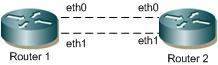
Boostrap Router Topology
Configuration
Router 1
#configure terminal | Enter configure mode. |
(config)#ip pim bsr-candidate eth1 | Configure eth1 of Router 1 as C-BSR. The default priority is 64, so it is not necessary to designate a priority. |
(config)#commit | Commit the transaction. |
#configure terminal | Enter configure mode. |
(config)#ipv6 pim bsr-candidate eth1 | Configure eth1 of Router 1 as C-BSR. The default priority is 64, so it is not necessary to designate a priority. |
(config)#commit | Commit the transaction. |
Router 2
#configure terminal | Enter configure mode. |
(config)#ip pim bsr-candidate eth1 10 25 | Configure eth1 of Router 2 as C-BSR with a hash mask length of 10, and a priority of 25. |
(config)#ip pim rp-candidate eth1 priority 0 | Configure interface eth1 as C-RP with a priority of 0. |
(config)#commit | Commit the transaction. |
#configure terminal | Enter configure mode. |
(config)#ipv6 pim bsr-candidate eth1 10 25 | Configure eth1 of Router 2 as C-BSR with a hash mask length of 10, and a priority of 25. |
(config)#ipv6 pim rp-candidate eth1 priority 0 | Configure interface eth1 as C-RP with a priority of 0. |
(config)#commit | Commit the transaction. |
Router 2 Unicast BSM
When the ip pim unicast-bsm command is configured on an interface that is a DR for a network, then that interface unicasts the stored copy of BSM to the new or rebooting router.
#configure terminal | Enter configure mode. |
(config)#interface eth1 | Enter interface mode for eth1. |
(config-if)#ip pim dr-priority 10 | Configure eth1 as DR |
(config-if)#ip pim unicast-bsm | Enable sending and receiving of Unicast BSM for backward compatibility. |
(config-if)#commit | Commit the transaction. |
(config)#end | End the session |
#configure terminal | Enter configure mode. |
(config)#interface eth1 | Enter interface mode for eth1. |
(config-if)#ipv6 pim dr-priority 10 | Configure eth1 as DR |
(config-if)#ipv6 pim unicast-bsm | Enable sending and receiving of Unicast BSM for backward compatibility. |
(config-if)#commit | Commit the transaction. |
(config)#end | End the session |
Validation
1. Verify the C-BSR state on Router 1.
#show ip pim bsr-router
PIMv2 Bootstrap information
This system is the Bootstrap Router (BSR)
BSR address: 20.0.1.21
Uptime: 00:01:39, BSR Priority: 64, Hash mask length: 10
Next bootstrap message in 00:00:53
Role: Candidate BSR
State: Elected BSR
FOR IPV6
#show ipv6 pim bsr-router
PIMv2 Bootstrap information
This system is the Bootstrap Router (BSR)
BSR address: 1001::1
Uptime: 00:00:04, BSR Priority: 64, Hash mask length: 12
Next bootstrap message in 00:00:03
Role: Candidate BSR
State: Elected BSR
Candidate RP: 3001::2(xe47)
Advertisement interval 4 seconds
Next C-RP advertisement in 00:00:03
2. Verify the C-BSR state on Router 2.
The initial state of C-BSR is P-BSR before transitioning to C-BSR. The two states are illustrated in the sample outputs from the show ip pim bsr-router command below.
#show ip pim bsr-router
PIMv2 Bootstrap information
BSR address: 20.0.1.21
Uptime: 00:02:39, BSR Priority: 64, Hash mask length: 10
Expires: 00:00:03
Role: Candidate BSR
State: Pending BSR
#FOR IPV6
show ipv6 pim bsr-router
PIMv2 Bootstrap information
BSR address: ::
Uptime: 00:00:04, BSR Priority: 0, Hash mask length: 0
Expires: 00:00:01
Role: Candidate BSR
State: Pending BSR
Candidate RP: 3001::2(xe47)
Advertisement interval 4 seconds
Next C-RP advertisement in 00:00:01
#show ip pim bsr-router
PIMv2 Bootstrap information
BSR address: 20.0.1.21
Uptime: 00:40:20, BSR Priority: 64, Hash mask length: 10
Expires: 00:02:07
Role: Candidate BSR
State: Candidate BSR
Candidate RP: 20.0.1.11(eth2)
Advertisement interval 60 seconds
Next C-RP advertisement in 00:00:02
Backoff cnt 1
FOR IPV6
#show ipv6 pim bsr-router
PIMv2 Bootstrap information
This system is the Bootstrap Router (BSR)
BSR address: 1001::1
Uptime: 00:00:04, BSR Priority: 64, Hash mask length: 12
Next bootstrap message in 00:00:03
Role: Candidate BSR
State: candidate BSR
Candidate RP: 3001::2(xe47)
Advertisement interval 4 seconds
Next C-RP advertisement in 00:00:03
#show ip pim rp mapping
PIM Group-to-RP Mappings
Group(s): 224.0.0.0/4
RP: 20.0.1.11
Info source: 20.0.1.21, via bootstrap, priority 0
Uptime: 00:02:17, expires: 00:02:26
Override RP cnt: 0
FOR IPV6
# show ipv6 pim rp mapping
PIM Group-to-RP Mappings
Override RP cnt: 0
Group(s): ff00::/8, Static
RP: 1001::1
Uptime: 01:19:29
Embedded RP Groups:
3. Verify RP-set information on E-BSR.
R1#show ip pim rp mapping
PIM Group-to-RP Mappings
This system is the Bootstrap Router (v2)
Group(s): 224.0.0.0/4
RP: 20.0.1.11
Info source: 20.0.1.11, via bootstrap, priority 0
Uptime: 00:00:22, expires: 00:02:12
Override RP cnt: 0
FOR IPV6
# show ipv6 pim rp mapping
PIM Group-to-RP Mappings
Override RP cnt: 0
Group(s): ff00::/8, Static
RP: 1001::1
Uptime: 01:19:29
Embedded RP Groups:
4. Verify RP-set information on C-BSR.
ARP1#show ip pim rp mapping
PIM Group-to-RP Mappings
Override RP cnt: 0
Anycast-RP 1.1.1.152 members :
4.4.4.5 7.7.7.1 23.23.23.1
Group(s): 224.0.0.0/4, Static
RP: 1.1.1.152
Uptime: 00:00:37
FOR IPV6
ARP1## show ipv6 pim rp mapping
PIM Group-to-RP Mappings
Override RP cnt: 0
Group(s): ff00::/8, Static
RP: 1001::1
Uptime: 01:19:29
Embedded RP Groups:
GROUP T0 RP MAPPING CONFIGURATION.
Each Protocol Independent Multicast - Sparse Mode (PIM-SM) router in
a PIM domain that supports Any Source Multicast (ASM) maintains
Group-to-RP mappings that are used to identify a Rendezvous Point
(RP) for a specific multicast group. PIM-SM has defined an algorithm
to choose a RP from the Group-to-RP mappings learned using various
mechanisms. This algorithm does not consider the PIM mode and the
mechanism through which a Group-to-RP mapping was learned.
Configure Static RP
#configure terminal | Enter configure mode. |
(config)#ip pim rp-address 10.10.10.1 | Statically configure an RP address for multicast groups. |
(config)#commit | Commit the transaction. |
#configure terminal | Enter configure mode. |
(config)#ipv6 pim rp-address 1001::1 | Statically configure an RP address for multicast groups. |
(config)#commit | Commit the transaction. |
Embedded RP, with IPv6 multicast, is a very cool trick. It simply embeds the RP IPv6 address as part of the multicast group address. This way, when a multicast router sees the group address, it can extract the RP and begin to use it for the shared tree
#
configure terminal | Enter configure mode. |
(config)#ip pim rp embedded enable | configure an RP embeded for multicast groups. |
(config)#commit | Commit the transaction. |
#configure terminal | Enter configure mode. |
(config)#ipv6 pim rp embedded enable | configure an RP embeded for multicast groups. |
(config)#commit | Commit the transaction. |
Here is the sample configuration for Router_ D:
hostname Router_ D
!
interface eth0
!
interface eth1
ip pim sparse-mode
!
interface eth2
ip pim sparse-mode
!
interface lo
!
!
Ip multicat-routing
!
ip pim rp-address 10.10.10.1
ip pim rp embedded enable
- - !
FOR IPV6
hostname Router_ D
!
interface eth0
!
interface eth1
ipv6 pim sparse-mode
!
interface eth2
ipv6 pim sparse-mode
!
interface lo
!
!
Ipv6 multicat-routing
!
Ipv6 pim rp-address 1001::1
Ipv6 pim rp embedded enable
- !
#FOR IPV6
show ipv6 pim sparse-mode rp mapping
PIM Group-to-RP Mappings
Override RP cnt: 0
Group(s): ff00::/8, Static
RP: 3001::1
Uptime: 08:29:50
Embedded RP Groups:
Anycast-RP Configuration
The Anycast-RP feature provides load balancing among active RPs and redundancy in a PIM-SM network domain. In a PM-SM configuration, only a single active RP for each multicast group within a domain is permitted. However, in an Anycast-RP configuration, this restriction is removed with the support of multiple active RPs for each group in a domain.
OcNOS supports Anycast-RP using the PIM implementation. In PIM Anycast-RP, Multicast Source Discovery Protocol (MSDP) is not employed to share information about active sources. Instead the Register mechanism in PIM is extended to provide this same function.
The following describes Anycast-RP in PIM-SM:
• A Unicast IP address is used as the RP address. The address is statically configured, and associated with all PIM routers throughout the domain.
• A set of routers in the domain is chosen to act as RPs for this RP address. These routers are called the Anycast-RP set.
• Each router in the Anycast-RP set is configured with a loopback address. The loopback address is configured on all RPs for the loopback interface, then configured as the RP address (static RP), and injected into OSPF using redistribute connected. The PIM-SM implementation uses only the first non-loopback address configured on the loopback interface. Therefore, it is important to be sure that the Anycast-RP address is configured with the first non-loopback address.
• Each router in the Anycast-RP set also needs a separate IP address, which is used for communication between the RPs.
• The RP address, or a prefix that includes the RP address, is injected into the unicast routing system inside the domain.
• Each router in the Anycast-RP set is configured with the addresses of all other routers in the Anycast-RP set. This must be consistently configured in all RPs in the set.
Topology
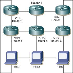
Anycast RP Topology
Host1 and Host3 act as hosts and sources for sending join and multicast data packets; Host2 acts as a host.
ARP1, ARP2 and ARP3
#configure terminal | Enter the Configure mode. |
(config)#interface lo | Enter the loopback interface. |
(config-if)#ip address 1.1.1.152/32 secondary | Configure the IP address for loopback |
(config-if)#exit | Exit the Configure mode. |
(config)#ip pim rp-address 1.1.1.152 | Configure the static RP with the address of the loopback. |
(config)#ip pim anycast-rp 1.1.1.152 4.4.4.5 | Configure the member RP address. In this example, 4.4.4.5 is the member RP in ARP2. It is the address used for communication between all RPs. |
(config)#ip pim anycast-rp 1.1.1.152 7.7.7.1 | Configure the member RP address. In this example, 7::7 is the member RP in ARP3. It is the address used for communication between all RPs. |
(config)#ip pim anycast-rp 1.1.1.152 23.23.23.1 | Configure the member RP address. In this example, 23.23.23.1 is the member RP in ARP1. It is the address used for communication between all RPs. |
(config)#commit | Commit the transaction. |
(config)#end | End the session |
#configure terminal | Enter the Configure mode. |
(config)#interface lo | Enter the loopback interface. |
(config-if)#ipv6 address 2000::1 secondary | Configure the IP address for loopback |
(config-if)#exit | Exit the Configure mode. |
(config)#ipv6 pim rp-address 1001::1 | Configure the static RP with the address of the loopback. |
(config)#ipv6 pim anycast-rp 1001::1 2001::1 | Configure the member RP address. In this example, 2001::1 is the member RP in ARP2. It is the address used for communication between all RPs. |
(config)#ipv6 pim anycast-rp 1001::1 2002::2 | Configure the member RP address. In this example, 2002::2is the member RP in ARP3. It is the address used for communication between all RPs. |
(config)#ipv6 pim anycast-rp 1001::1 8000::1 | Configure the member RP address. In this example, 8000::1 is the member RP in ARP1. It is the address used for communication between all RPs. |
(config)#commit | Commit the transaction. |
(cpnfig)#end | End the session |
Disable Anycast-RP
#configure terminal | Enter configure mode. |
(config)#no ip pim anycast-rp 1.1.1.152 | Disable Anycast-RP. |
(config)#no ip pim rp-address 1.1.1.152 | Disable static RP. |
(config)#commit | Commit the transaction. |
#configure terminal | Enter configure mode. |
(config)#no ipv6 pim anycast-rp 1001::1 | Disable Anycast-RP. |
(config)#no ipv6 pim rp-address 1001::1 | Disable static RP. |
(config)#commit | Commit the transaction. |
Validation
1. Verify RP-mapping in ARP1.
#show ip pim rp mapping
PIM Group-to-RP Mappings
Override RP cnt: 0
Anycast-RP 1.1.1.152 members:23.23.23.1
Group(s): 224.0.0.0/4, Static
RP: 1.1.1.152
Uptime: 00:00:13s
FOR IPV6
#show ipv6 pim rp mapping
PIM Group-to-RP Mappings
Override RP cnt: 0
Anycast-RP 1001::1 members :
2002::1 2001::1
Group(s): ff00::/8, Static
RP: 8000::1
Uptime: 00:05:1
2. Verify RP-mapping in ARP1 after disabling anycast-RP and RP-address.
ARP1#show ip pim rp mapping
PIM Group-to-RP Mappings
Override RP cnt: 0
Anycast-RP 1.1.1.152 members :
4.4.4.5 7.7.7.1 23.23.23.1
Group(s): 224.0.0.0/4, Static
RP: 1.1.1.152
Uptime: 00:00:37
FOR IPV6
ARP1#show ipv6 pim rp mapping
PIM Group-to-RP Mappings
Override RP cnt: 0
Anycast-RP 1001::1 members :
2002::1 2001::1
Group(s): ff00::/8, Static
RP: 8000::1
Uptime: 00:05:1