Topology
In the below example PE1 and PE2 forms a MLAG domain.
As shown in Figure 14-32, PE1 and PE2 are a single logical switches to P3 and P4. Even if either PE1 or PE2 is down, there exists a path to reach other destinations.
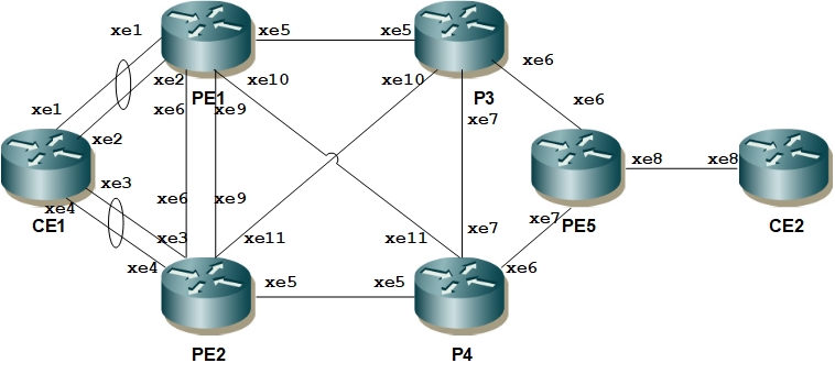
Figure 14-32: MLAG Topology
Last modified date: 10/12/2023