Topology
Figure 26-142 shows and example of subinterface configuration. In this example, there are two routers, R1 and R2, and the eth1 interface of R1 is connected directly to eth2 of R2 using an Ethernet cable.
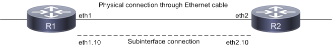
Figure 26-142: Subinterface connections
The eth1.10 subinterface is created on R1, and eth2.10 is created on R2.
Note: Layer 3 Subinterfaces can be created on physical and LAG interfaces.
Last modified date: 10/16/2023